Now it´s the time for a something bigger project, after my masterpiece (Sine curve) gets slowly long in the tooth.
The aim of the project is nearly similar how by my project Sine curve, briefly speaking I´ll try to build an ideal PC. But how it is by every ideal, it isn´t possible, you could only approach on it. Moreover everybody of us has another view of an ideal PC. But generally a PC should have a lot of performance (power), should be very silent, nobody around the world should have the same case, all people should stand in front of the PC and say only WOW and at least the PC should be as small as possible.
All who thinks now Yeah eventual a little gaming PC, I have to fail you, because the pc will have at the end a similar size how the Sine curve and the CoolIT PC. The reason for that is on the one hand that I don´t play a LAN-parties, so it doesn´t matter whether the PC weighs 5kg or 30kg. On the other I able to implement the other three features (performance, super silent and unique design).
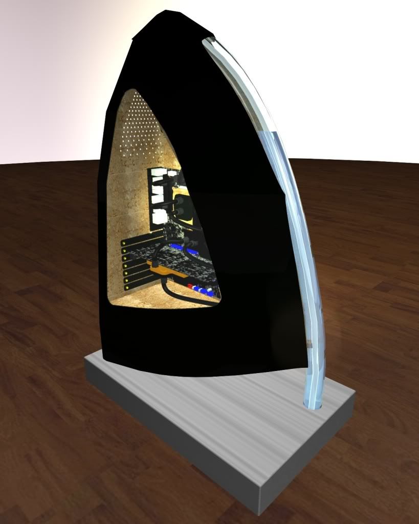
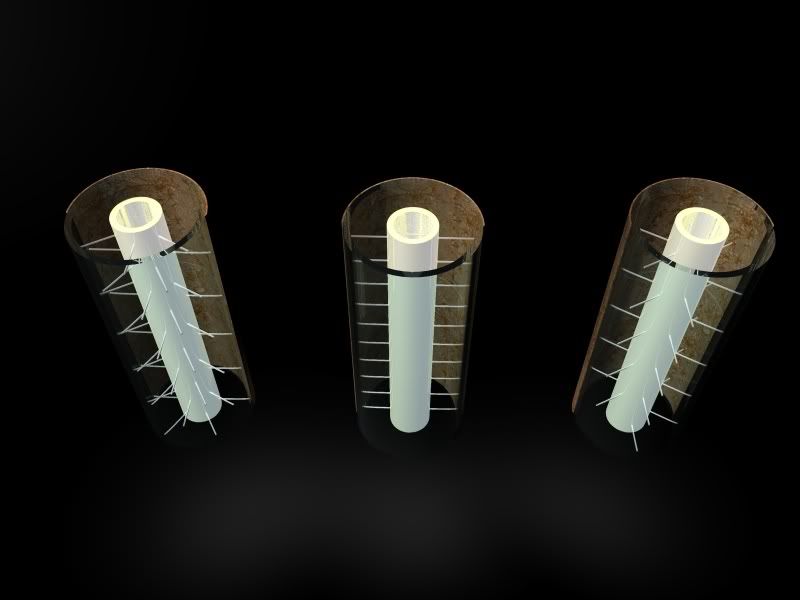
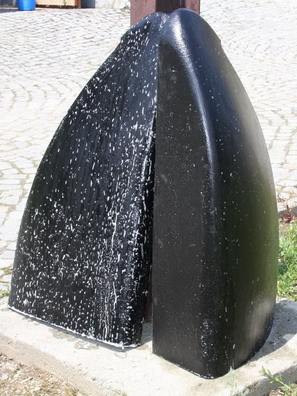
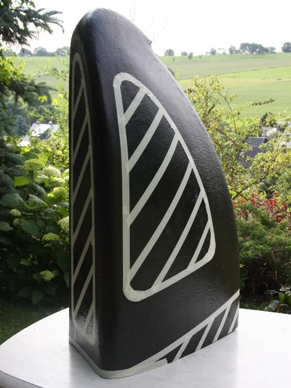
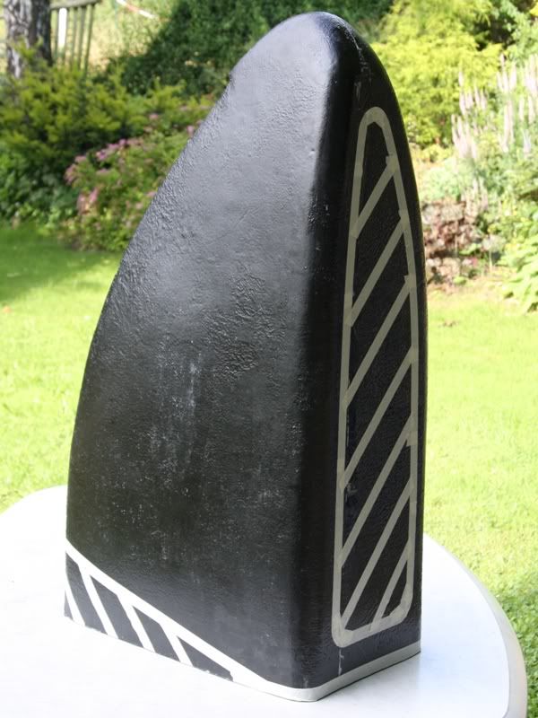
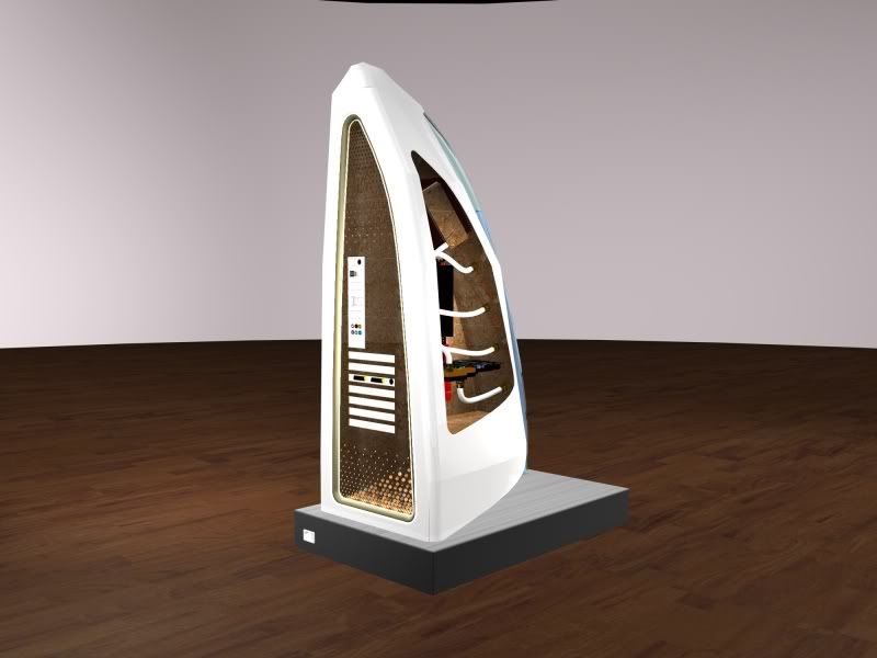
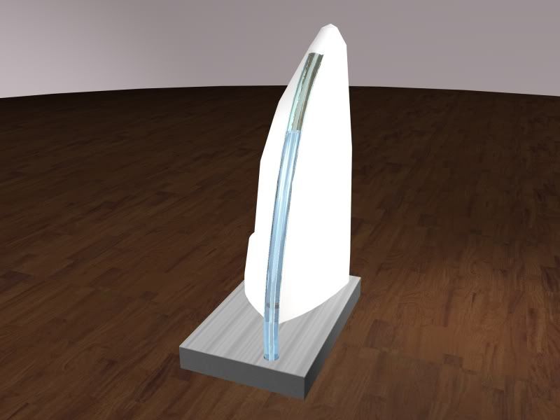
I want to create a computer in the shape of a sail that stands on a socket. The sail will be made of gfk and the socket of aluminum. A central theme will be the water-cooling system. The long Plexiglas tube in the front will be later the reservoir for the cooling circuit. In the tube with a diameter of 40mm will be a tube with a diameter of 12mm. This smaller tube has in the upper part a lot of very little holes. Through these holes the water that comes from the socket will splash at the inner site of the thicker tube. This has two advantages in my eyes, on the one hand the reservoir wouldn´t mist up and on the other hand it looks better. The reservoir will be illuminated by two Highpower LEDs, one at each of the two ends. For the cooling I take highly likely radiators from coolIT systems with peltier-elements, because they cool better than normal radiators.
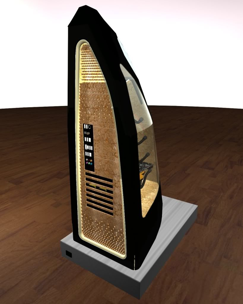
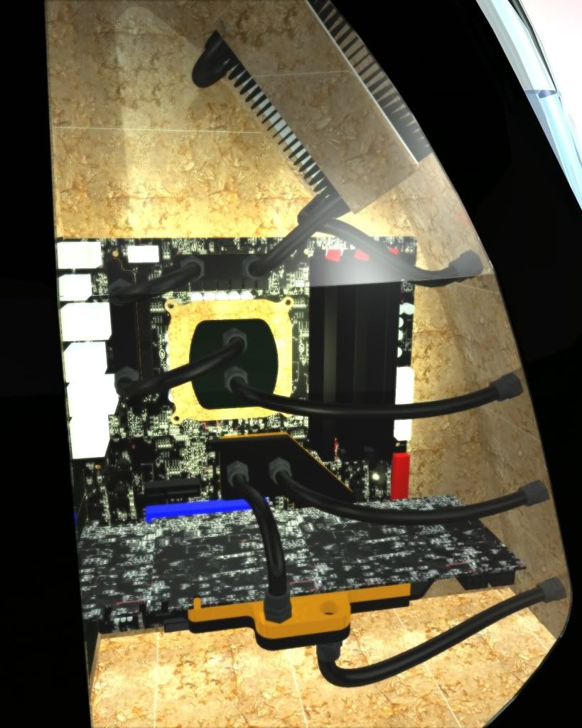
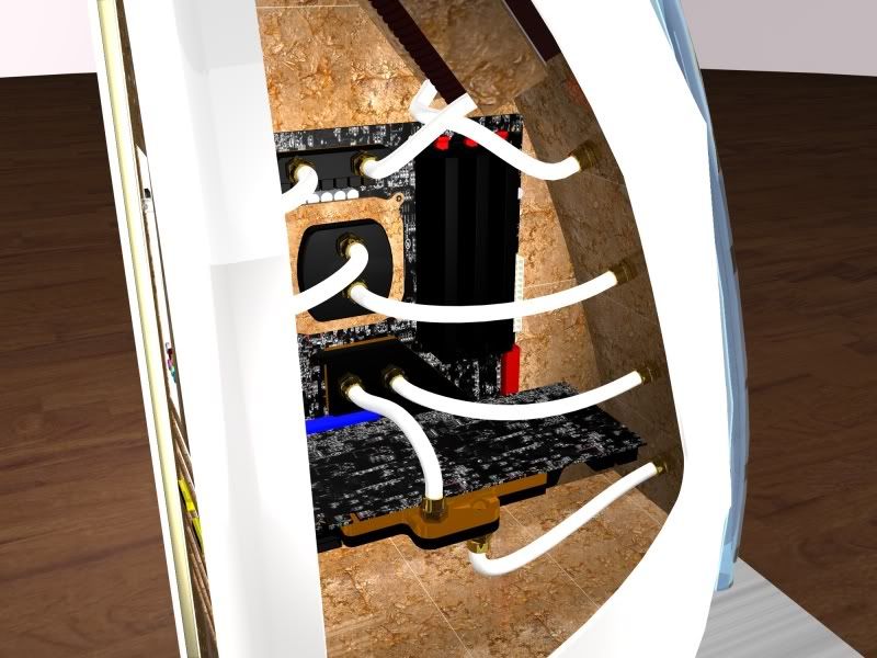
The inner case will be impressed with 24 carat leaf gilding. To get a contrast to the gold all hardware will be black just like the tubing and the water cooling fitting (black nickel). Moreover all cables will be sleeved with black sleeve. To get a great illumination the inner case will be illuminated by two high-power LEDs. Besides the two single radiators the PSU and the pump find a place in the lower part of the sail. The hdd/ssd and the optical drive find their place in the socket. The optical drive is at the back of the socket just like a 230V power connection.
At the back of the sail will be leaf gilding, too. These will be illuminated by 5mm diffuse LEDs, which shine how all the other LEDs in warm white.
Well after some words about my plan where the separate things find their place in the case I tell you something about the hardware I´ll use. But at first I want to say a big
THANK YOU
to all the following companies how support this project, because without them the project wouldn´t exist.
Because I´m not sure about all hardware I´ll use I start with the hardware with is to 99.9% sure
So and now we come to the hardware that I contemplate, but that isn´t sure.
Video card: GeForce GTX 280 or Radeon HD 4870 with at least 1GB RAM and also water-cooled with EK Waterblocks
HDD: 2 x 1TB
Optical drive: slimline slot-in DVD burner
Tubing/water cooling fittings: 10/8 black tubing and 10/8 black nickel fittings
Well I hope that I could give you a more or less good view about my idea for a nearly ideal PC. Certainly I am looking forward to criticism, suggestions, opinions etc. during the whole process of this project log.
Concluding it´s to say, that I´ll try to provide you each one or two weeks during the next 4 months, 4 days, 4 hours and 4 minutes, because after that it´s the 09/09/2009 9.09 o´clock (at least in Germany) and this is the ideal time for some (final) pictures of the wedding between the case and the hardware
05-05-2009, 12:24 AM
Spawn-Inc
Re: the golden sail
it looks nice and i like the tube routing.
i do have some concerns for the sake of your heat load and what you plan to do with it.
are you saying your using the coolit with the tec to cool, or just the rad from that unit? is that the only rad in the loop?
what pump are you using?
i wouldn't get the ek supreme if thats all going to be in the loop, its restrictive and does best in a cpu only loop with a good pump .
05-05-2009, 09:21 AM
SXRguyinMA
Re: the golden sail
another crazy project from you! +rep and +sub
05-05-2009, 07:54 PM
jdbnsn
Re: the golden sail
WOW! That is insanely cool!
05-05-2009, 09:33 PM
Ichbin
Re: the golden sail
If you make it crisp enough, I can see you winning some competitions and such. It's a nice clean design. Really can't wait to see how it turns out.
05-07-2009, 05:31 AM
Eclecticos
Re: the golden sail
An unusual but unique design none the less. Reservoir placement is interesting.
I really like the 3D animation, and renderings. Interested in seeing more of this. +Rep
05-07-2009, 06:28 AM
DonT-FeaR
Re: the golden sail
i would sub but i look at every project so.. no point
good luck
05-12-2009, 06:36 PM
D.Heiße
Re: the golden sail
So I think it´s time to inform you about the current situation of the project. Unfortunately I could show/tell/write, because I haven´t the Plexiglas tube for the reservoir yet, but I´ll should get it this week.
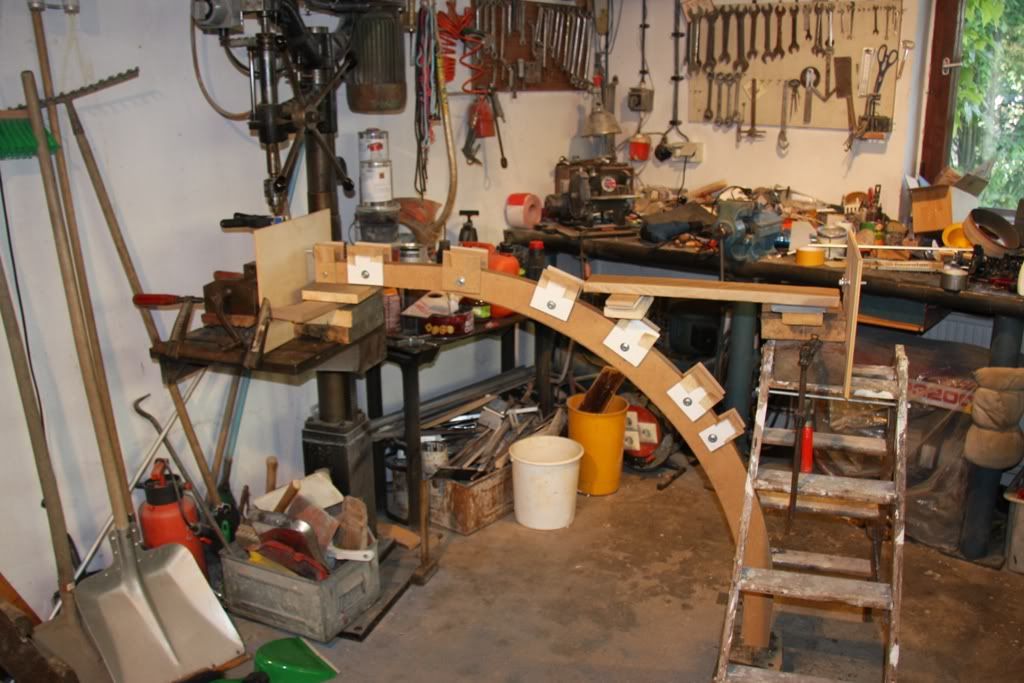
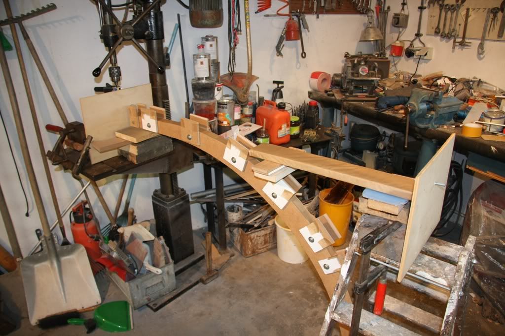
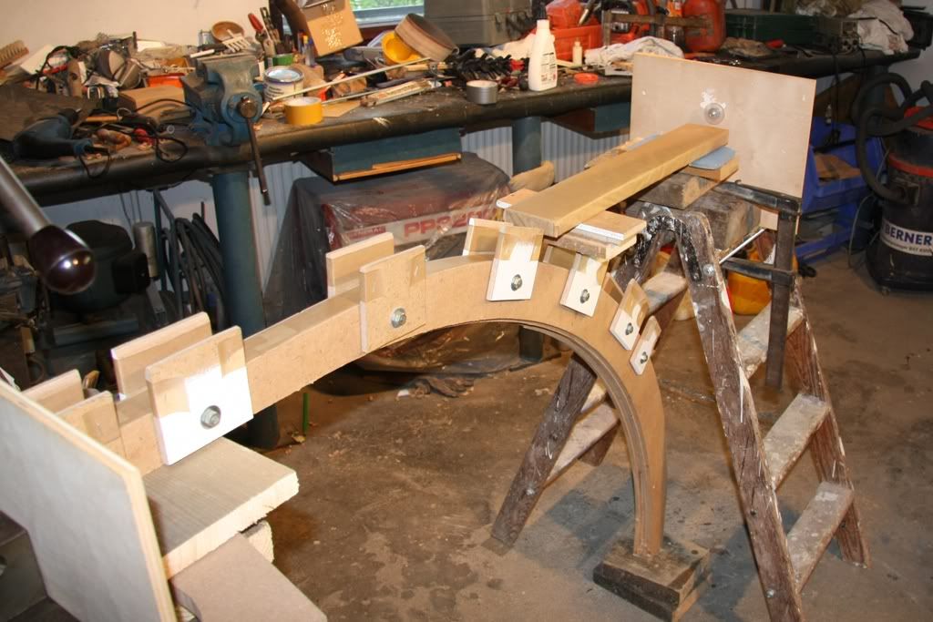
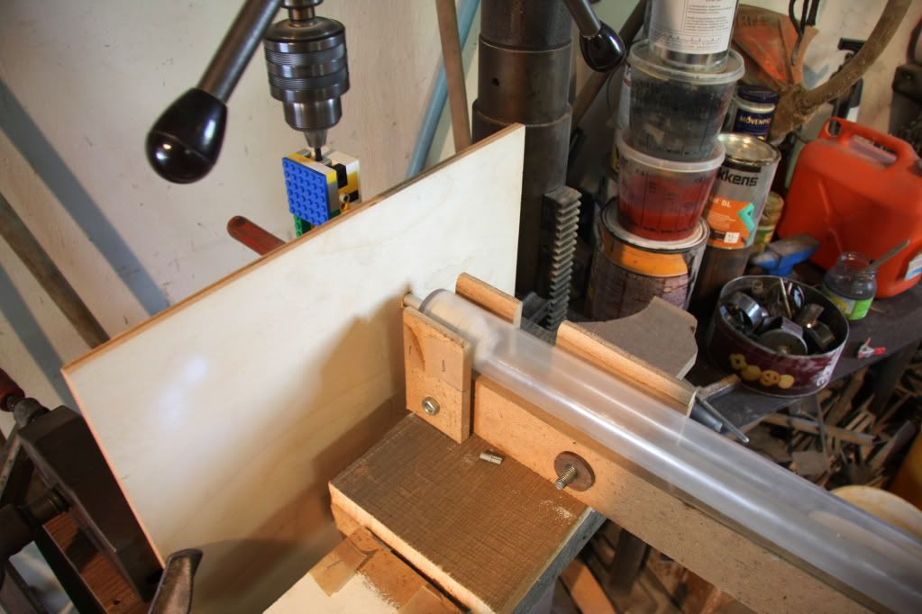
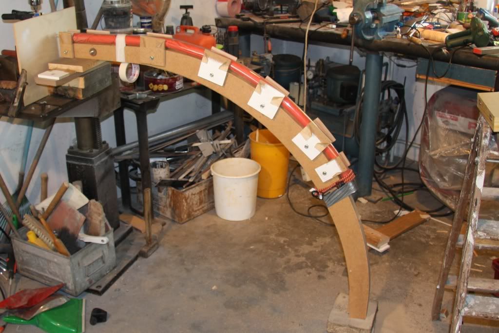
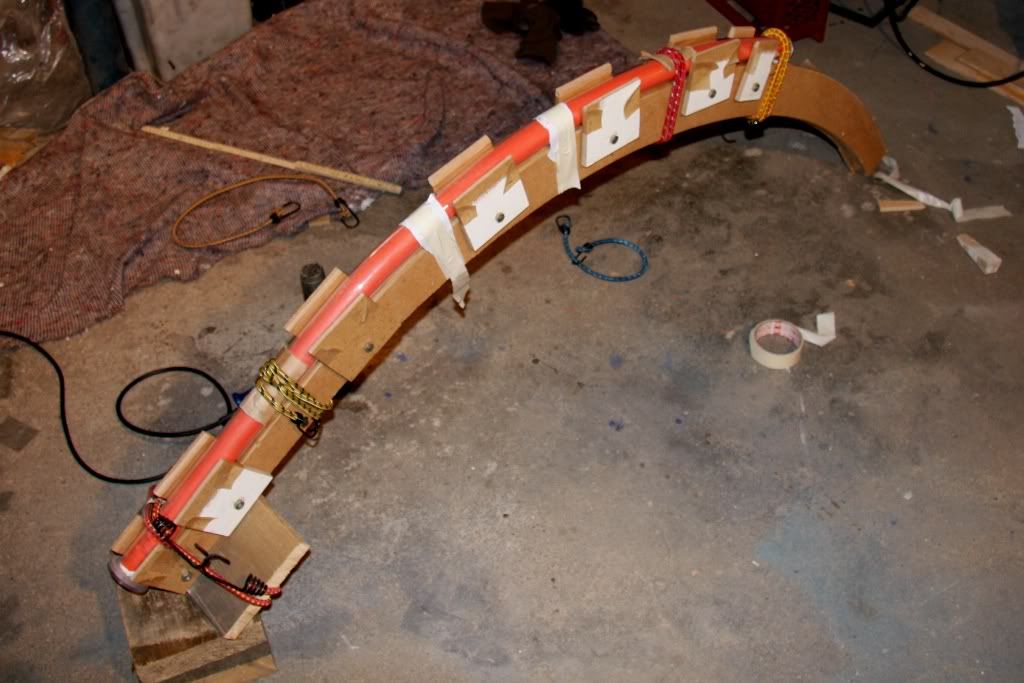
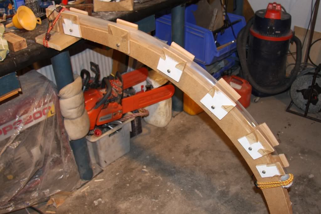
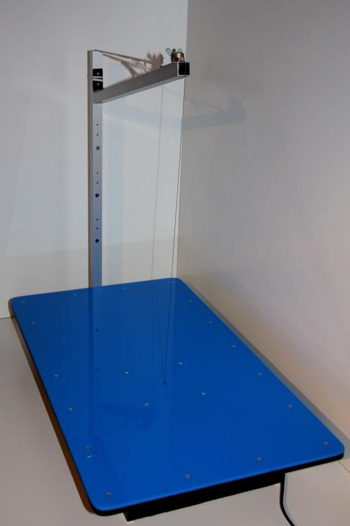
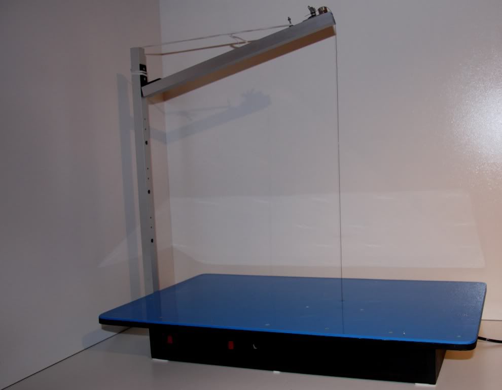
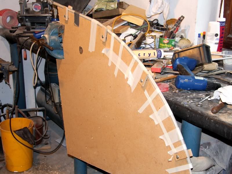
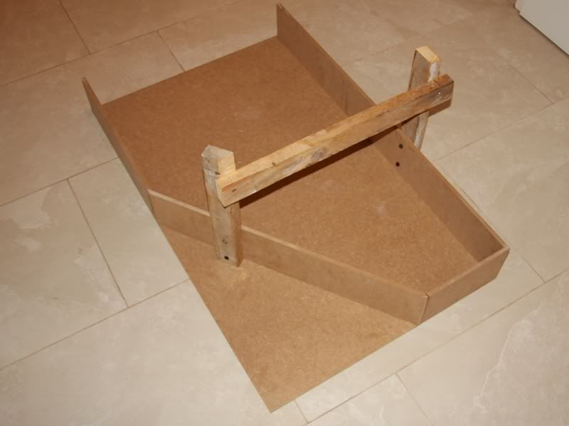
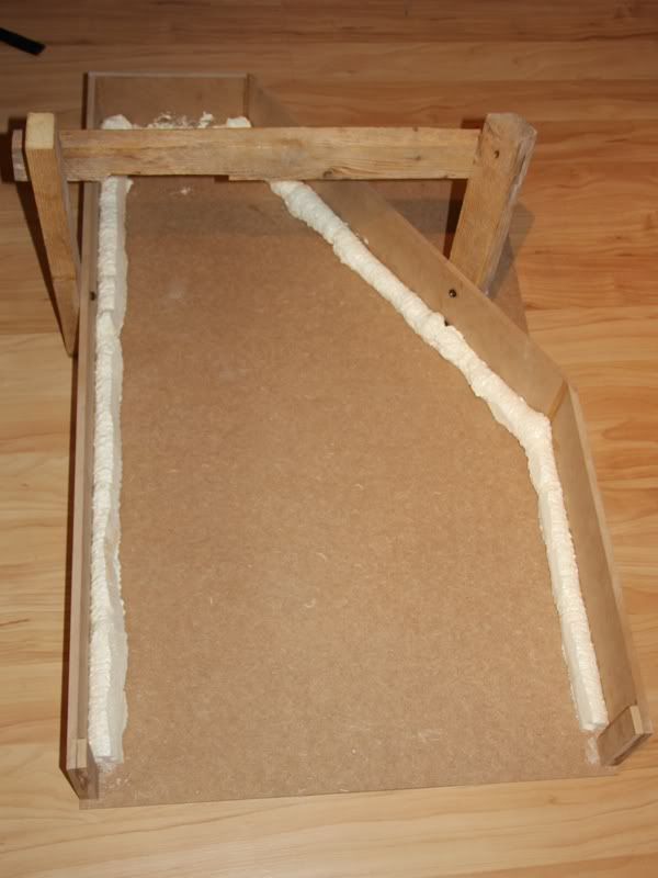
Nonetheless I build the appliance to warm up and bend the tube. This was indeed more difficult than I thought, because nowhere I founded some progress reports about bending a 130cm long Plexiglas tube. Therefore I had to think of myself how I´ll bend such a tube, whereby to bend it isn´t such a big problem rather to warm it up. For this problem I had two ideas. The first one was to build a box in that I put the form over which I would bend the tube and the tube itself. This box should headed up by a hot air blower, but I think that is very difficult to get a constant temperature in it for maybe 20 minutes, so I discard this idea. Because of this I´ll try my fortune with my second idea. At this the tube will rotate and I´ll try to warm it up with two hot air blowers. Certainly I don´t know if my deliberations are right, but I´ll know it after the first attempt. Well that you have a better imagination what my idea is, here some pictures of the bend-setup, indeed without the tubing, that I´ll glue between the two Plexiglas slices.
Unfortunately this was all that I made last week, and I couldn´t write anymore. The only thing that I could say is that the aluminum socket will be most likely a stainless steel socket.
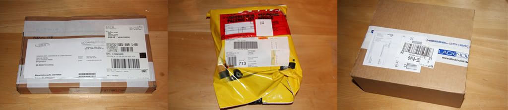
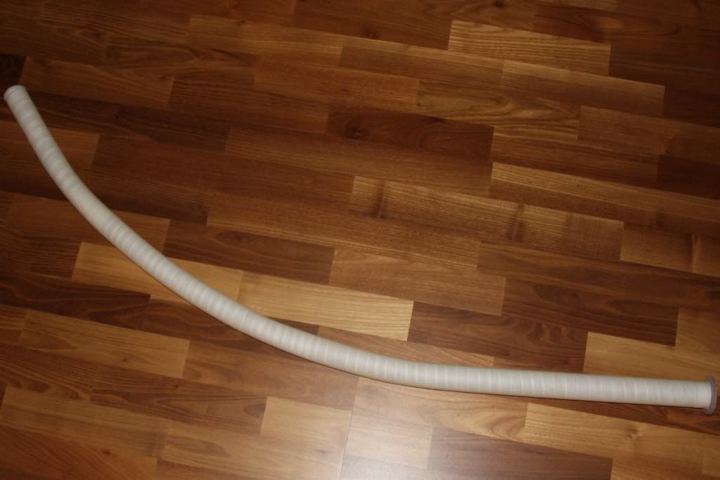
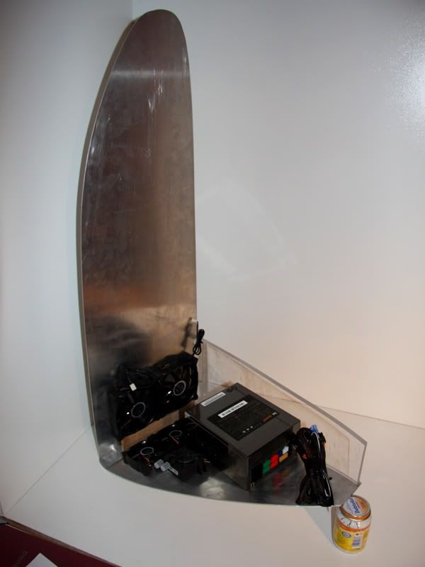
At least a picture that the postmen bring me last week
what inside is I´ll show you in one of the next updates.
@Spawn-Inc: Well I´ll use the coolIT with the tec, whether one, two or three I dont. But if I´ll only use one, I´ll use a 240mm normale radiator moreocer.
@SXRguyinMA/jdbnsn/Ichbin/Electgicos/dont-FeaR: Thank you and I try that your aren´t disappointed!!!
05-13-2009, 02:46 AM
DonT-FeaR
Re: the golden sail
very nice bend set up mate.. good work so far.
05-13-2009, 04:59 AM
billygoat333
Re: the golden sail
wow... that sail is big. lol
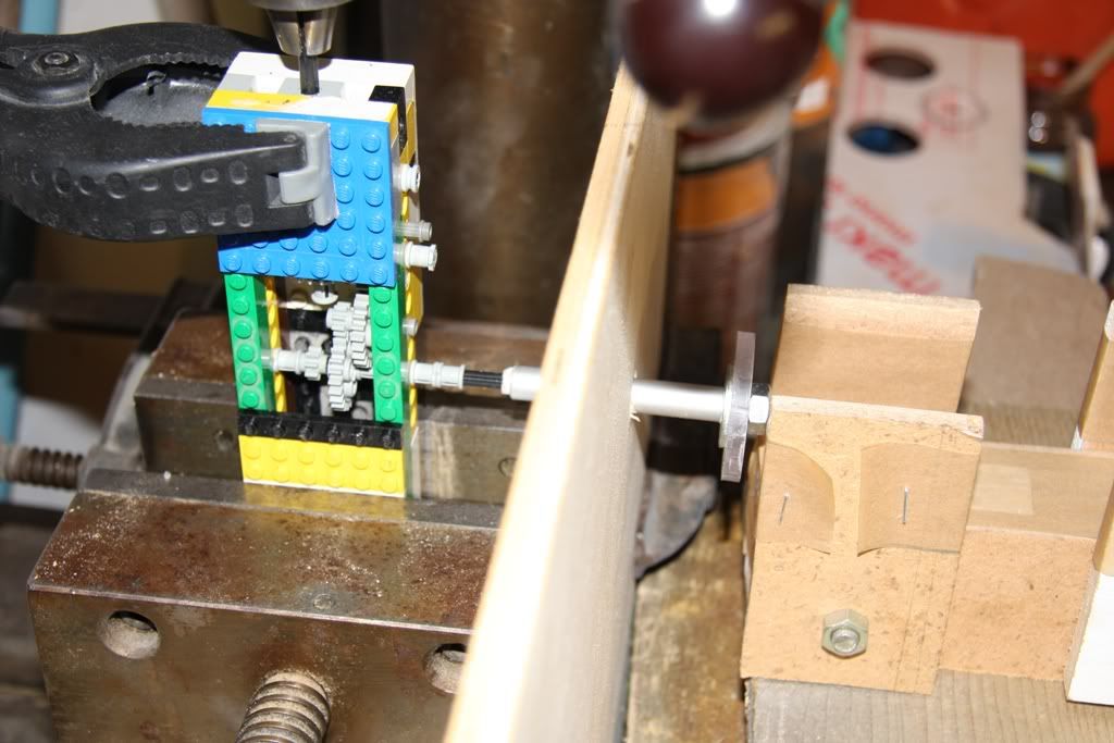
way to use legos! they rock. :)
05-13-2009, 12:56 PM
p0Pe
Re: the golden sail
soooo.... this might sound wierd, but what about filling that huge pipe with sand, so that you get the least collapsing when you bed it? that way it will bend totally even over the whole place, and i barely think you will need to rotate it:) it will get some weight into the pipe too, that will help force bend it downwards.
05-14-2009, 12:03 AM
Spawn-Inc
Re: the golden sail
Quote:
Originally Posted by p0Pe
soooo.... this might sound wierd, but what about filling that huge pipe with sand, so that you get the least collapsing when you bed it? that way it will bend totally even over the whole place, and i barely think you will need to rotate it:) it will get some weight into the pipe too, that will help force bend it downwards.
not weird, good idea. i know in trumpet making the use frozen soapy ice water. or so how it's made shows.
05-14-2009, 03:41 AM
p0Pe
Re: the golden sail
Quote:
Originally Posted by Spawn-Inc
not weird, good idea. i know in trumpet making the use frozen soapy ice water. or so how it's made shows.
wouldnt that make the heating very dificult since the water will cool the pipe? sand is way worse at optaining heat.
05-14-2009, 05:02 PM
Spawn-Inc
Re: the golden sail
Quote:
Originally Posted by p0Pe
wouldnt that make the heating very dificult since the water will cool the pipe? sand is way worse at optaining heat.
it was done with a tube bender, not heated. like exhausts. then i think once it's put together they put it through a heating cycle but i don't remember that part.
05-26-2009, 05:17 PM
D.Heiße
Re: the golden sail
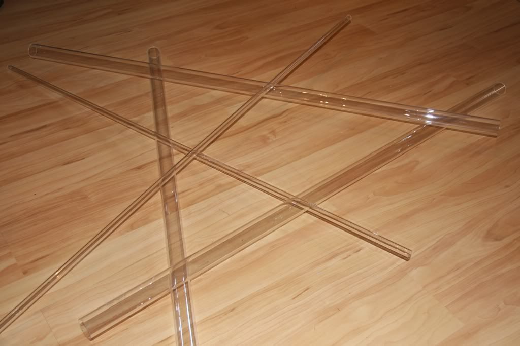
Now I want to get in touch, although I didn´t do a lot of the last two weeks, because of a little misunderstanding with the Plexiglas tubes. But at Monday I could hold the tubes in my hand. The tubes are sponsored by KÖNIG Kunststoffe
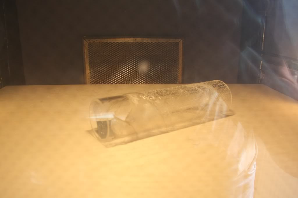
At first I take a piece of the tube and put it into the oven to test at that temperature the tube is bendable.
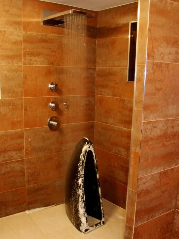
The result of the test was that the tube is bendable from 145°C and over 165° emerge bubbles in the Plexiglas. Now some people would ask themselves why I want to know this. Reason of this is that I got a great idea under the shower. The idea was to heat up the sand which I´ll fill into the tube. And this hot sand would warm up the tube very consistent.
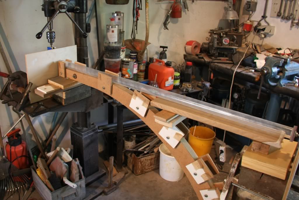
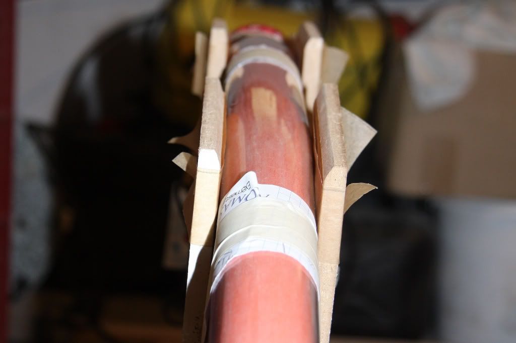
During the sand was in the oven I tested my spin mechanism with the cold tube and made some photos of it.
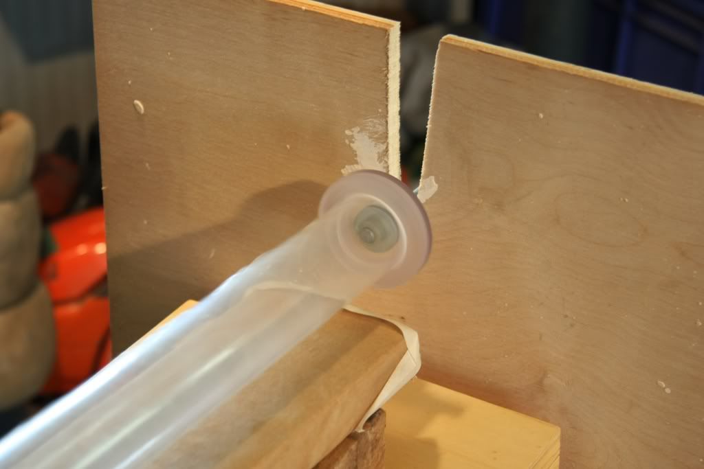
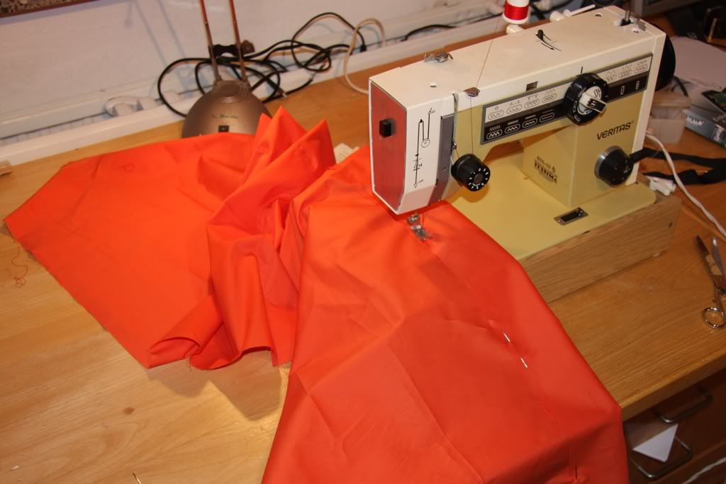
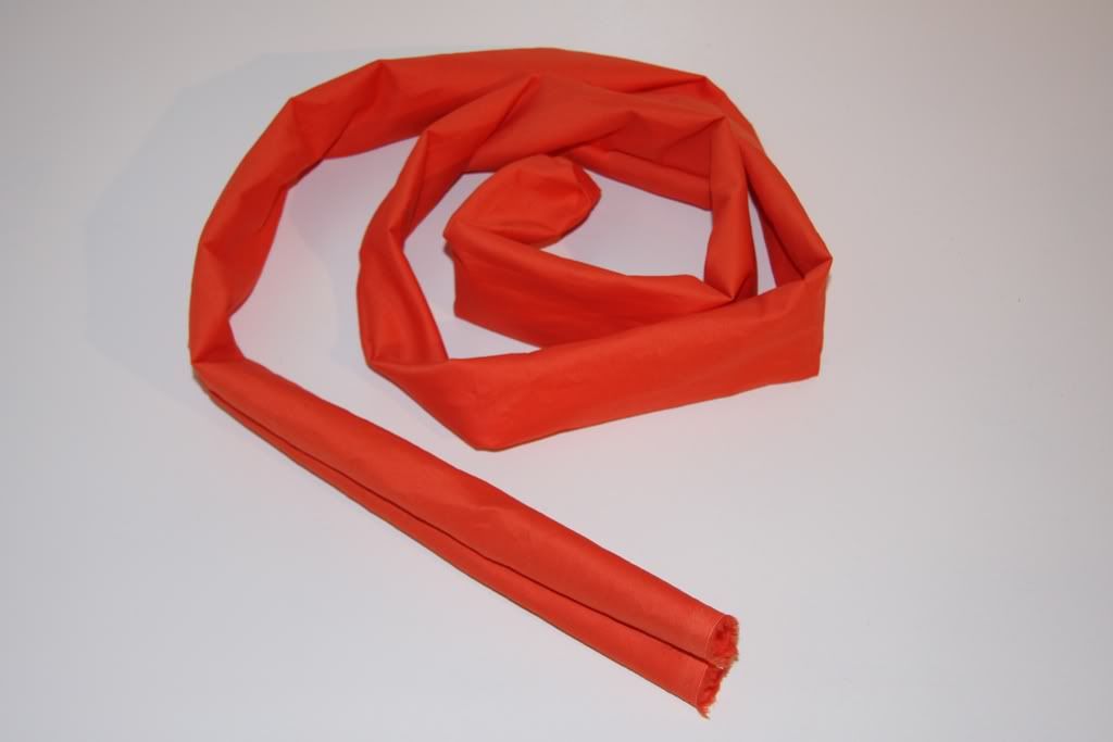
Before I put the hot sand into the tube I inserted a fabric tube into the Plexiglas tube. So the sand wouldn´t contact the Plexiglas tube and don´t scratch it. This fabric tube I sewed before two weeks.
Well and now the series of mishaps started. Unfortunately I haven´t no pictures of it, because I was alone at the shop. But I´ll try to explain it with words, if I´ll be successful I don´t know.
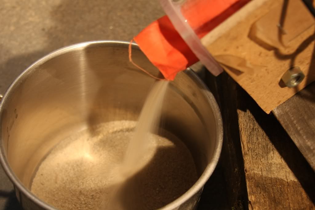
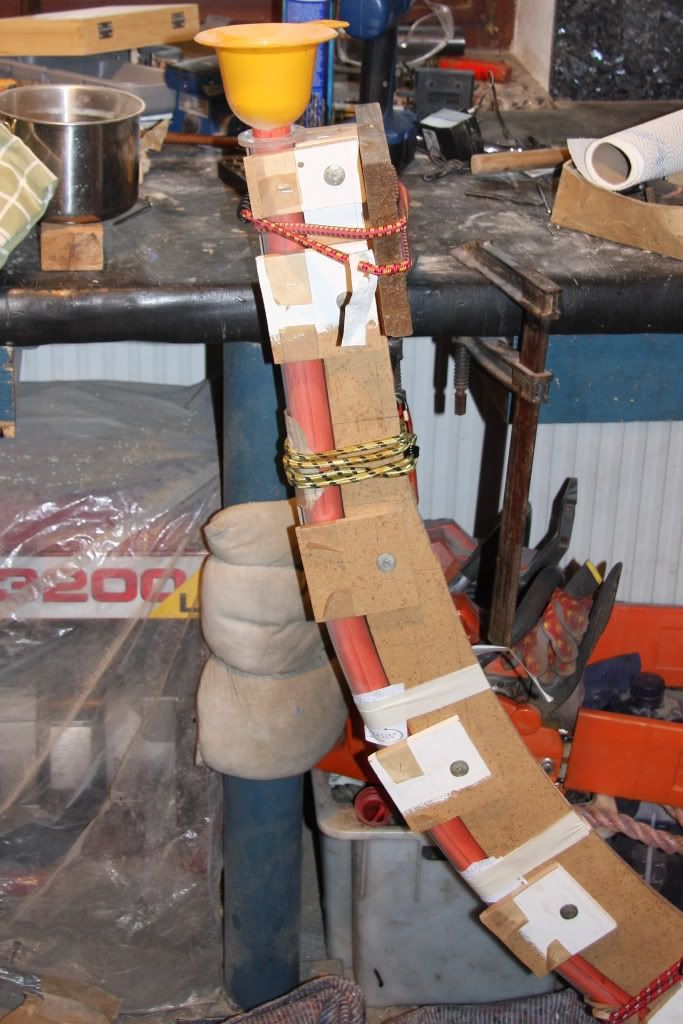
At first I fill the sand into the red fabric tube that was into the Plexiglas tube by the help of a funnel. That works relative good, but at the end a little bit sand flowed between the fabric tube and the Plexiglas tube, because I pour in too much sand into the funnel (mishap #1)
Ready with this I screwed down the tube and inserted it in the spin mechanism. Thereby I noticed the tube was a little bit bend. This wasn´t good at this moment, because the tube had an unbalance by the time of rotation. After some seconds the Lego gear were destroyed as result of the unbalance (mishap #2)
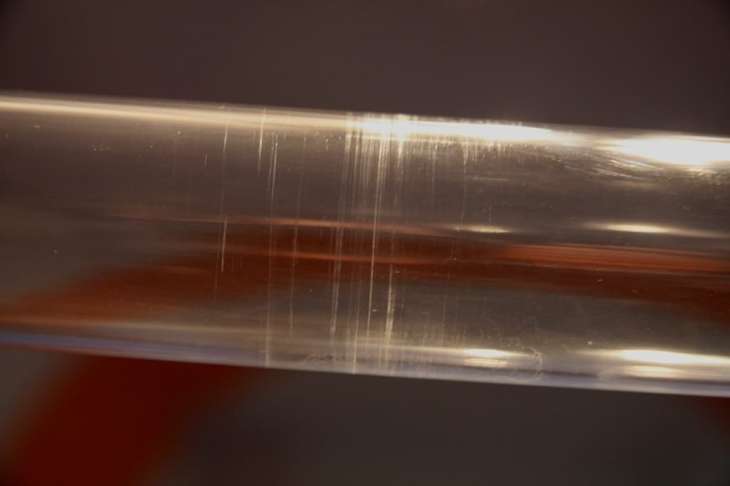
Well now I had to rotate the tube with the hand at this I noticed the tube had to grind at two sites, because at this sites were scratches around the tube (mishap #3)
After 5 minutes I had the feeling that the tube is ready to bend. I took it at one site out of the mounting and try to bend it. Unfortunately the tube wasn´t at one end and at a site in the middle smooth enough for bending, so the tube got a little kink at the middle (mishap #4)
The one end I had heat up again with the hot air blower that I hold in the one hand, and with the other hand I hold the tube that it could slide down. Because of this I hadn´t another hand for bending the tube and took my foot. The problem was, that I haven´t such a sensitivity in my foot. I put too much pressure onto the tube and the seal break away from the tube. So the sand flowed out of the tube (mishap #5)
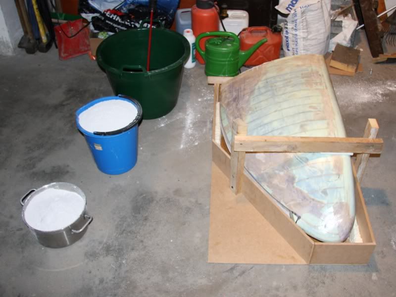
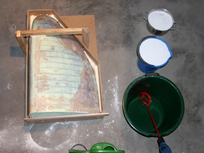
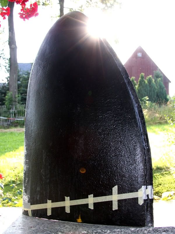
How you could see nearly all went wrong. At the following picture you could see how it looks at the end
And so looks the tube after I released all the sand of the Plexiglas tube
In my opinion the result isn´t really miserable, but I don´t like the kink and the scratches.
So I´ll try it once again in the hope that the next tube won´t have a kink and scratches. Certainly I´ll change some things.
The greatest modification is that I won´t use the spin mechanism again, because I won´t need it. I´ll heat up the tube at ca. 100°C with the hot air blower. After this I´ll fill in sand that is 175°C hot. And so the tube and the sand will be 155°C hot, and this temperature is enough to bend the tube.
In the hope that I´ll a get a great bend tube with my next try I´ll start with the Styrodur from this weekend.
Moreover I have some Hardware-News. Instead of the Aqaustream pump I´ll use a
Desweiteren gibt es noch ein paar Hardware-News. Statt der eigentlich geplanten Aquastream DDC pump taht I get from Laing. Besides I´ll get from OCZa Vertex 60GB SSD that will I use as for the OS. I also get support from Dremel and highly likely from Aquatuning.
Well and now I haven´t to write anything. But if you have questions please ask me and I´ll try to give you an answer. Moreover I would be happy about suggestions and criticism
05-26-2009, 06:45 PM
OvRiDe
Re: the golden sail
You are a mad man!! I love seeing ingenuity at work.
I think you did really good for a first run at it. I know if it were me I would have a flat kinked up tube and 3rd degree burns. :P
Looking forward to seeing how you make out on your next run, I know this is going to be a great build!
05-30-2009, 04:51 AM
D.Heiße
Re: the golden sail
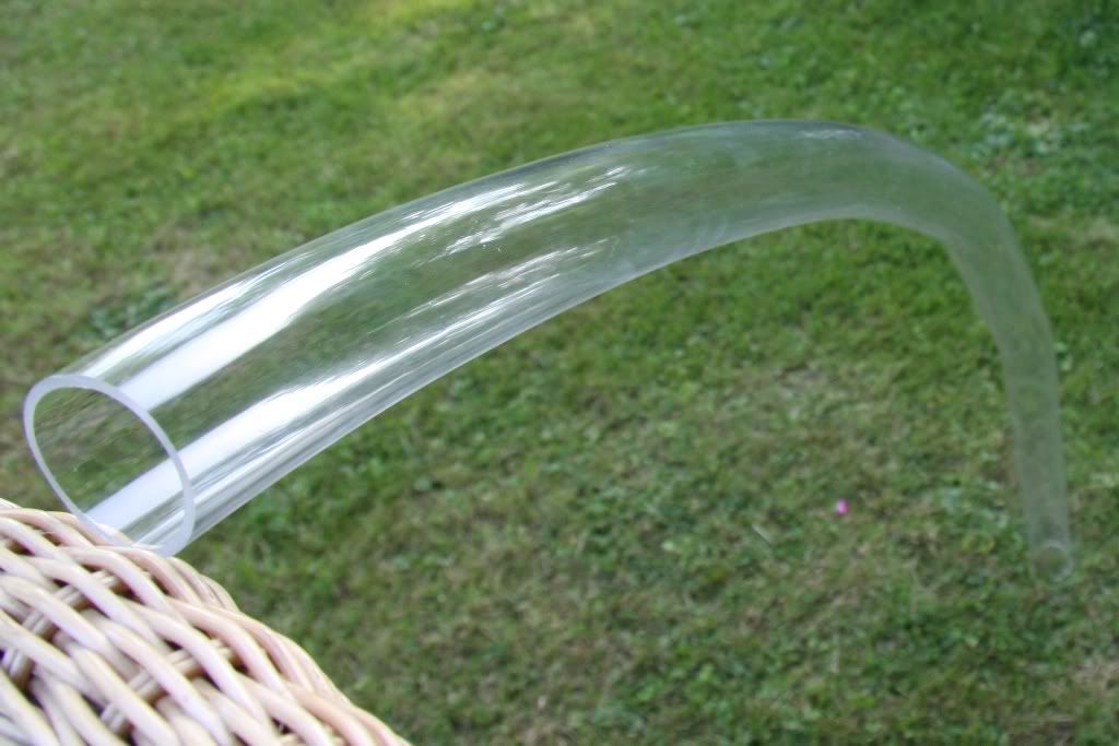
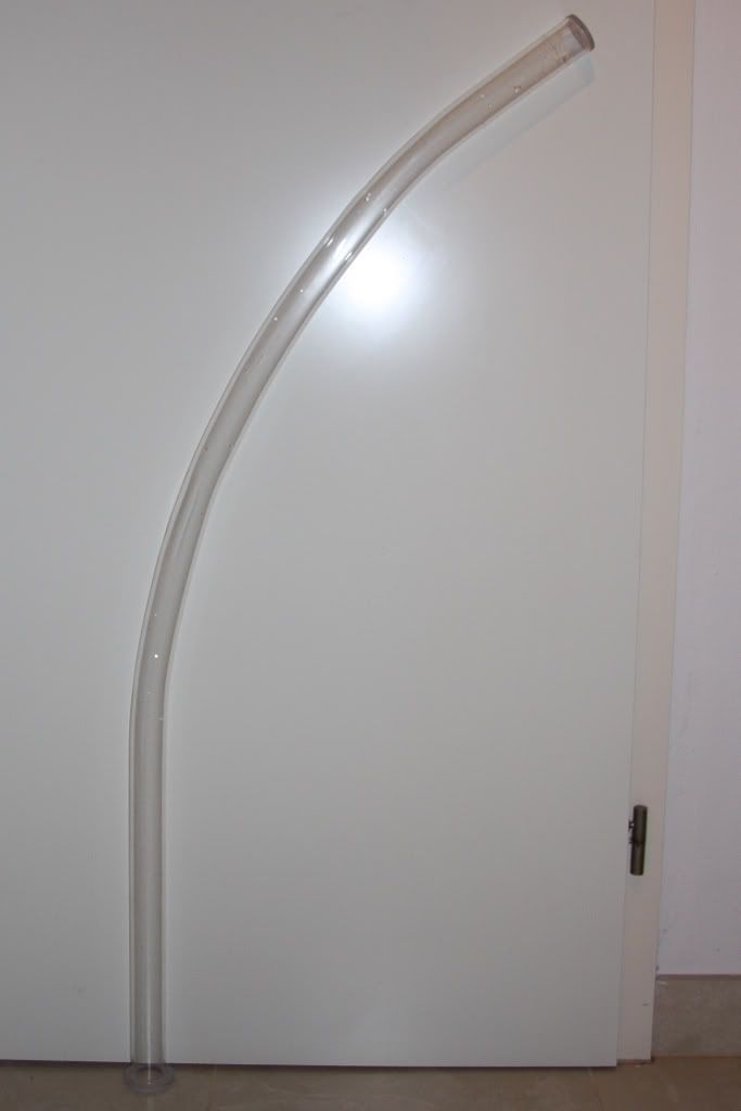
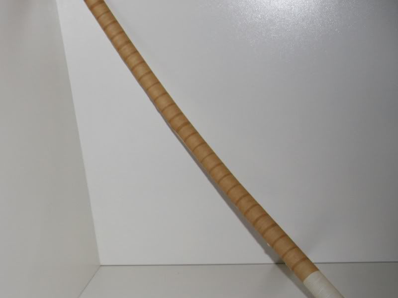
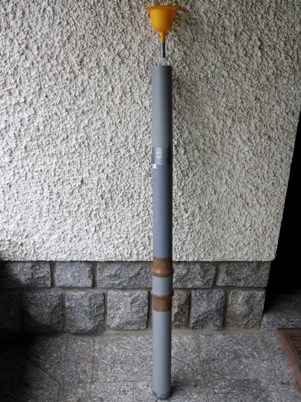
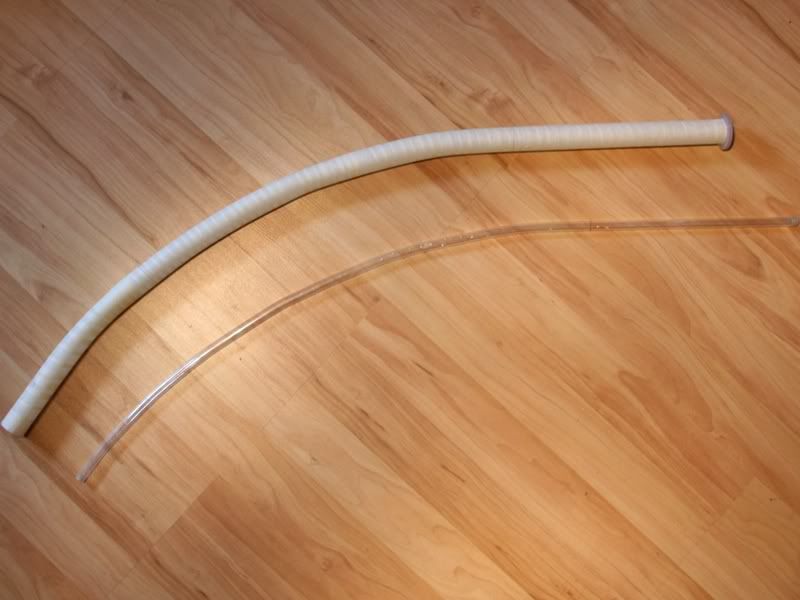
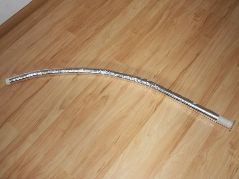
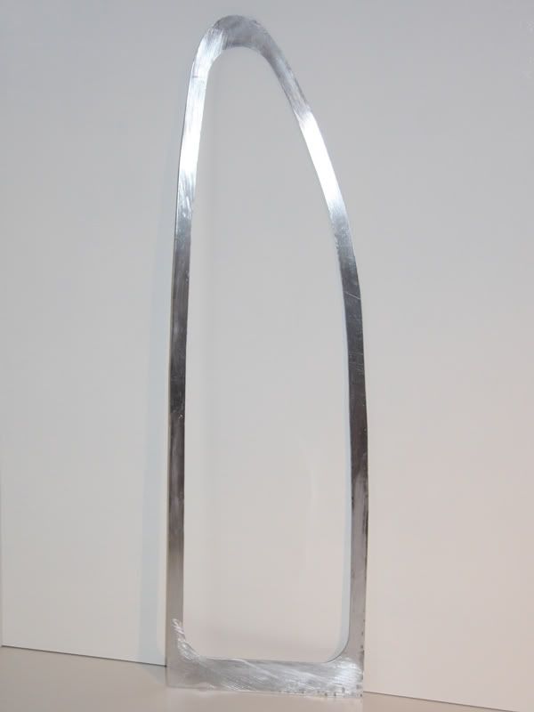
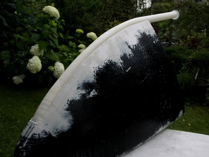
How I promised you I try to bend the Plexiglas tube again. I did all how I described in my last update and so looks the tube directly after the bend process
Than the sand was cold I let it drain out
and refill it with hot sand.
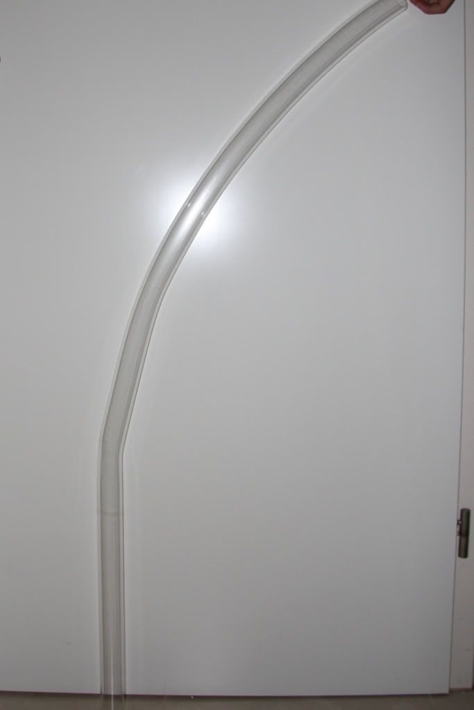
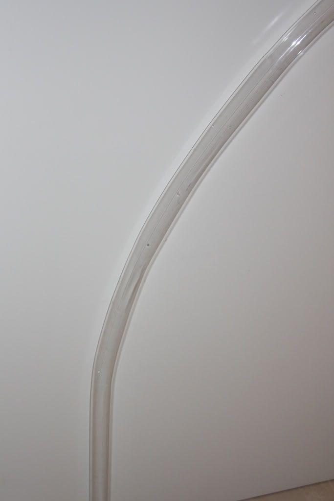
So looks the bend tube without the orange fabric hose.
After this I cleaned the tube with water to make some more pictures of it.
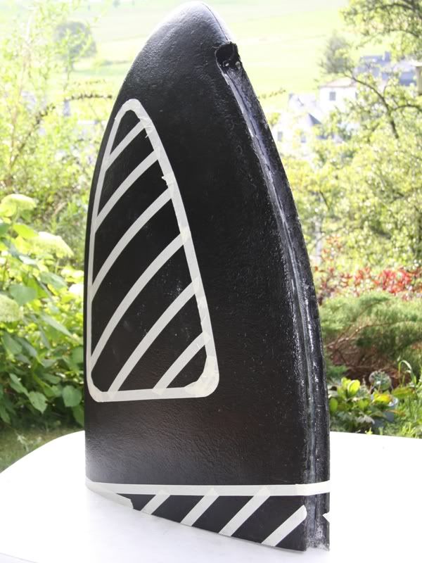
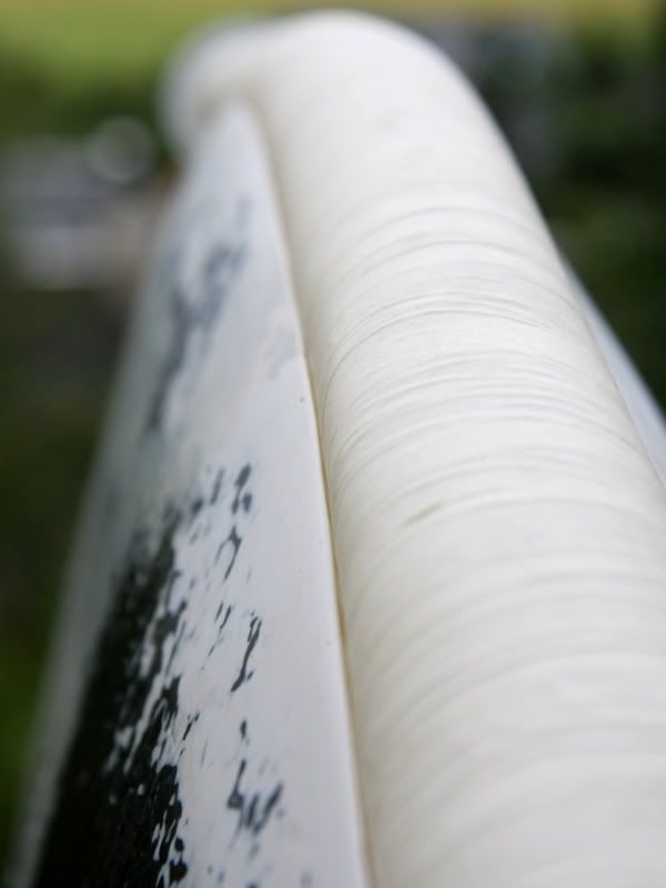
To protect the tube from scratches I swathed i tat first with stretch leaf and then with crepe tape
Well unfortunately I haven´t no more news from the build. Certainly there are two new hardware news. On the one hand I´ll use these compact black nickel fittings that I´ll from aquatuning. Moreover the T-Balancer will be employed to see the temperatures and the flow rate at the desktop.
06-03-2009, 11:32 AM
D.Heiße
Re: the golden sail
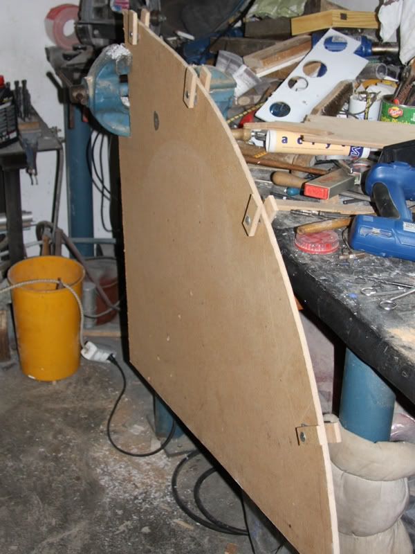
After I bended the tube more or less good I could start with the positive form of the sail. For this I built at first a Styrodur cutter/thermo saw. Certainly the saw didn´t work at the beginning. I planned to use a 20W transformer, but this worked only 5 minutes. Fortunately I had another transformer with 160W at home and also some 2.5 ohm resistive wire.
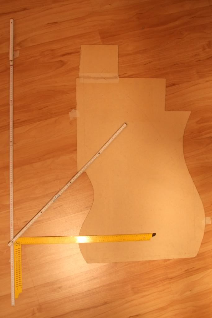
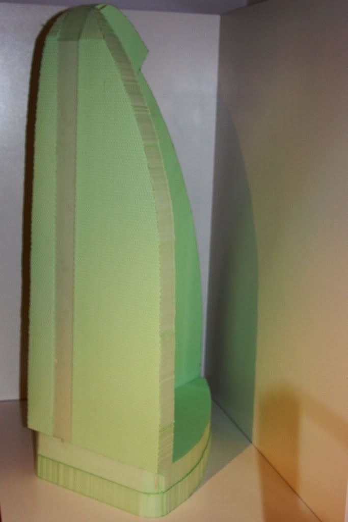
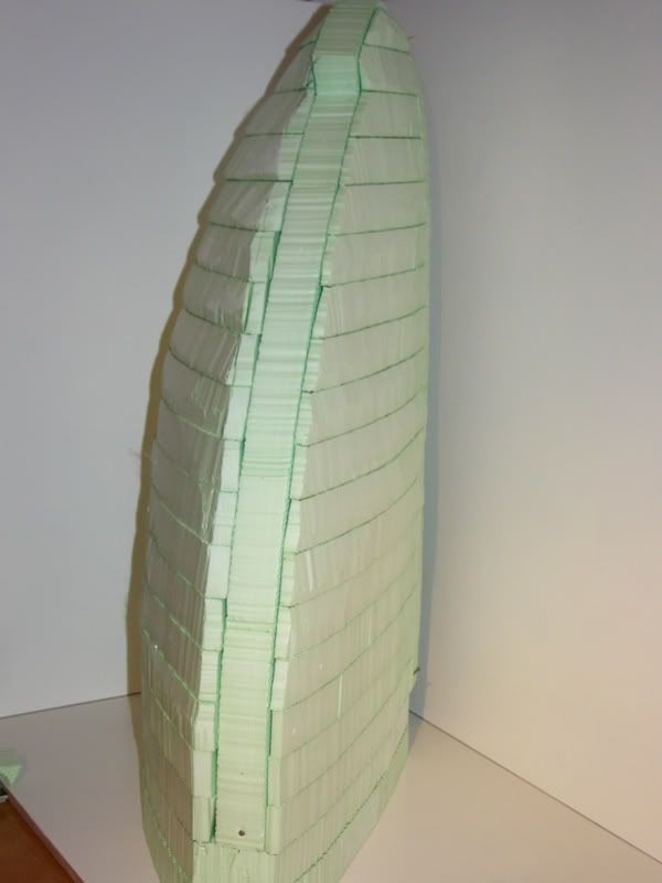
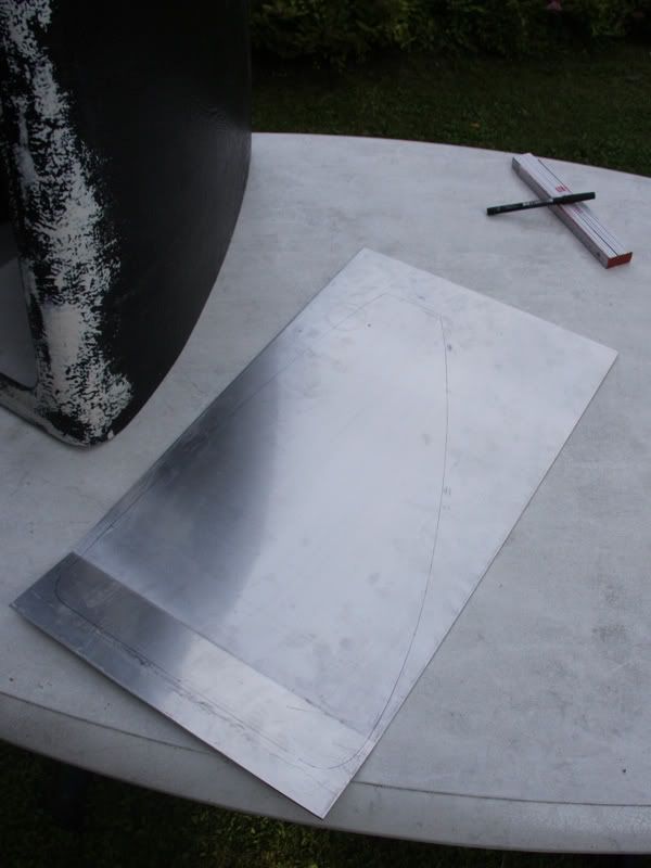
Ready with it I could start with cutting the Styrodur into shape. For this I made at first 3 stencils (bottom, back, side)
Now I started with cutting the 3 pieces into shape
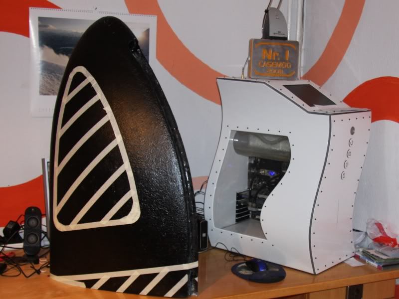
To get a better imagination of the size I put it near the Sine curve
I know that I will be a really big PC and that it´s possible to make it a little smaller, but more than 10% smaller isn´t possible. And if I´ll make it 10% smaller I would get at some sites space problems maybe. So I decided to make it rather a little bit bigger before I get into trouble with the space.
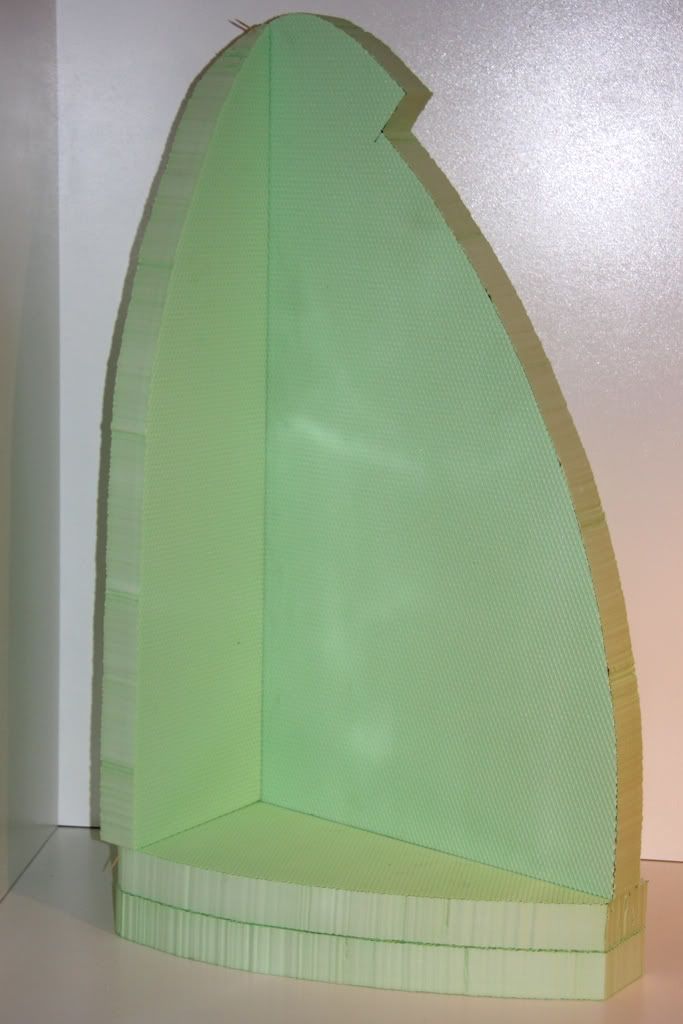
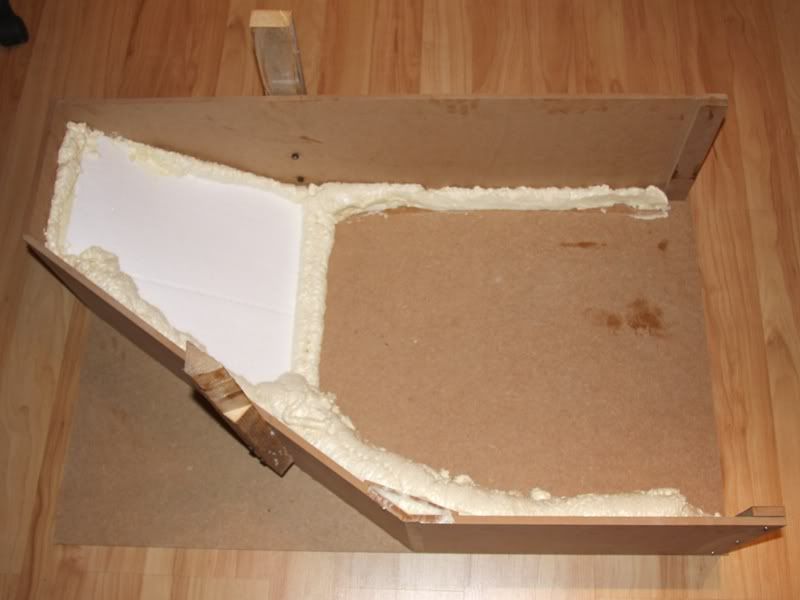
Ready with the “base frame“ I filled one site with Styrodur, for the other site I had no more time, but I´ll try to fill the other site tomorrow evening
@all: How could I change the title of the project log???
06-03-2009, 05:39 PM
Zeroignite
Re: the golden sail
To change the title, edit the subject line original post.
You win some reputation, good sir. Very ambitious project, and it seems to be coming along quite well.
06-13-2009, 01:50 AM
OvRiDe
Re: the golden sail
Nice Hotwire setup!
I can change the title for you, just PM me what you would like me to change it to.
Also since this is an active ongoing mod, I think we should move it to the Works In Progress section. I will move it after I receive your PM.
06-14-2009, 12:45 PM
D.Heiße
Re: the golden sail
I think it´s time for an update once again. These update will be a little bit bigger with 25 pictures.
After I filled the left site of the form with Styrodur, I had to fill the right site, too. Ready with it looks so
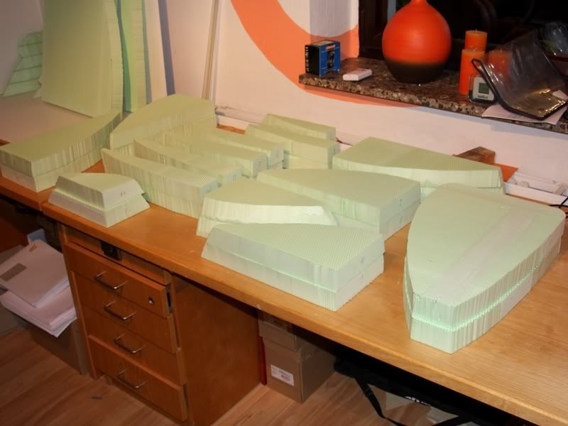
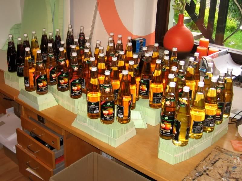
Now I had to glue the several pieces of the form. For this I thought it´s ideal to glue at first 4 pieces together and then the packages in the basic form. So I build pairs of two Stryodur pieces at first.
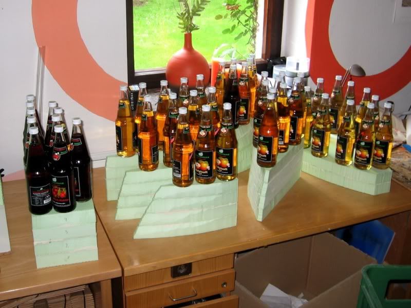
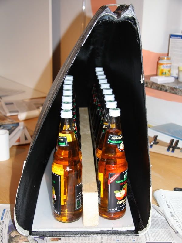
These pairs I glued with Styropor-/Stryodurglue that I bought in the DIY market for 7. To get a better result I ballast the separate pairs with glass bottles
After some hours I glued always two of this pairs together.
Nach ein paar Stunden habe ich dann jeweils 2 solcher Paare miteinander verklebt.
In the end I glued these packages in the basic form. Here I noticed that the packages weren´t very good and I would have a better result without these packages. But now it was too late and except 2 or 3 bigger slots it hasn´t more effects.
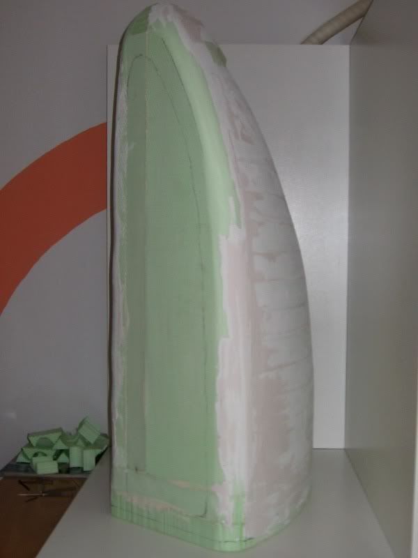
After the glue was dry I could started with grinding the shape and after two hours this was the result.
Certainly there were some holes in it, but all in all I was satisfied with the result and the holes I filled.
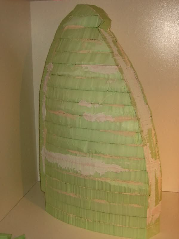
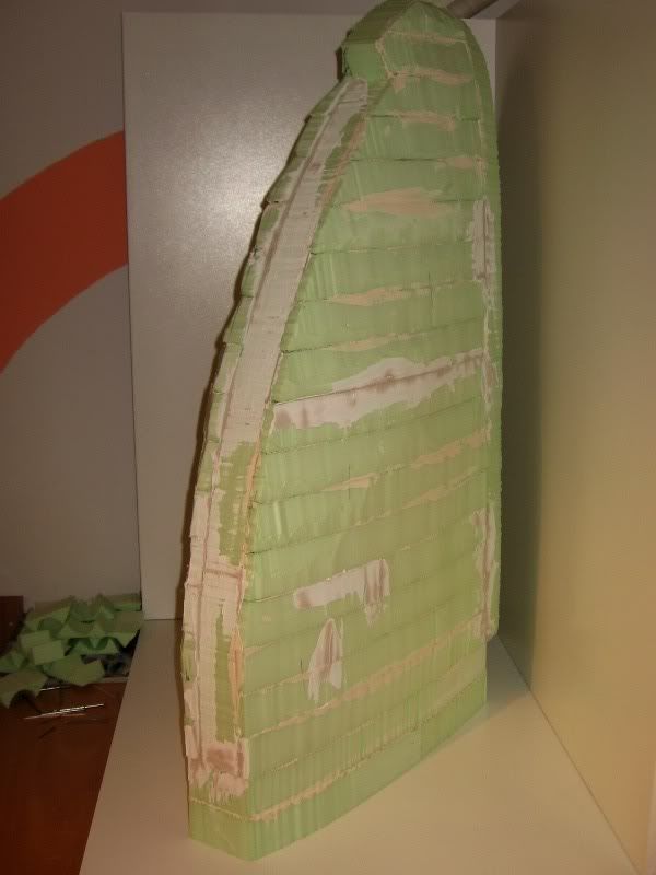
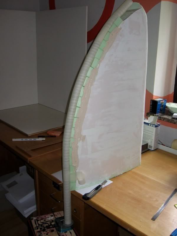
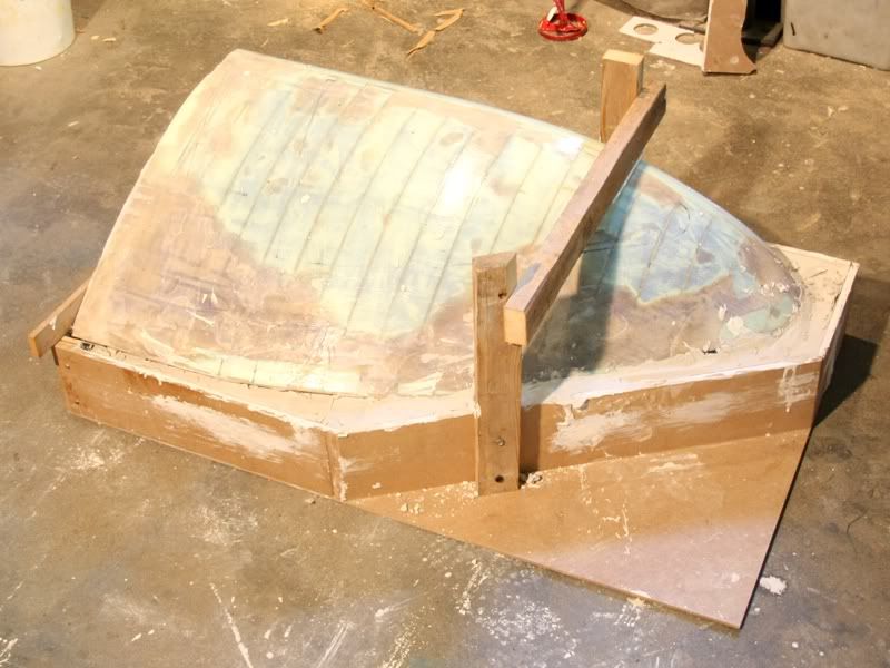
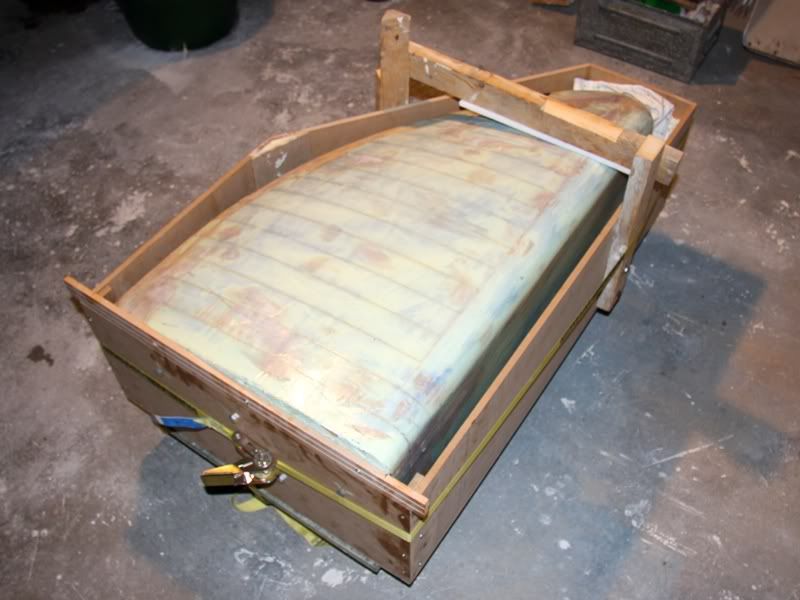
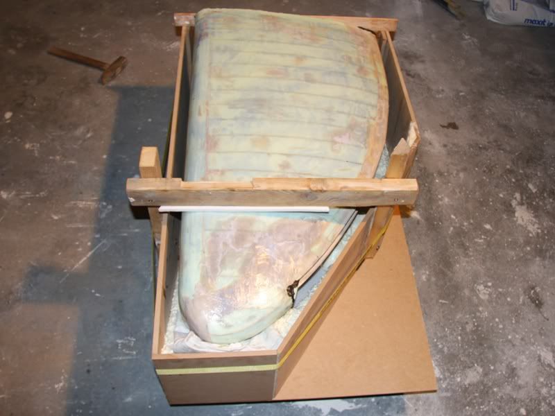
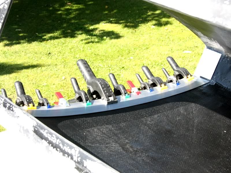
Ready with this I could start with the second heaviest work of the whole project. In fact after I bend the Plexiglas tube successfully (that was the heaviest work of the project) I had to adapt it very exactly. To realize this I cut out about 20 pieces that I glued at the front side. I aligned these while I press the tube into the immersion than the glue was still liquid.
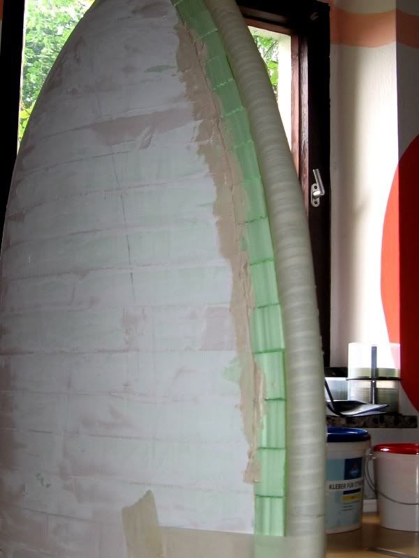
Naturally I had now firstly a rough form, because between the separate pieces there were slots how you could see here
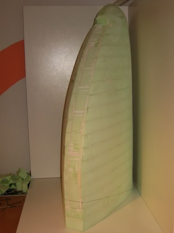
I had to fill these slots with filler, but this is easier said than done. To fill a 2cm radius freehand is not really easy (at least for me). To play it save I swathed the tube with baking paper at first.
Now I fill the slots generously with filler and then I press the tube in the filler.
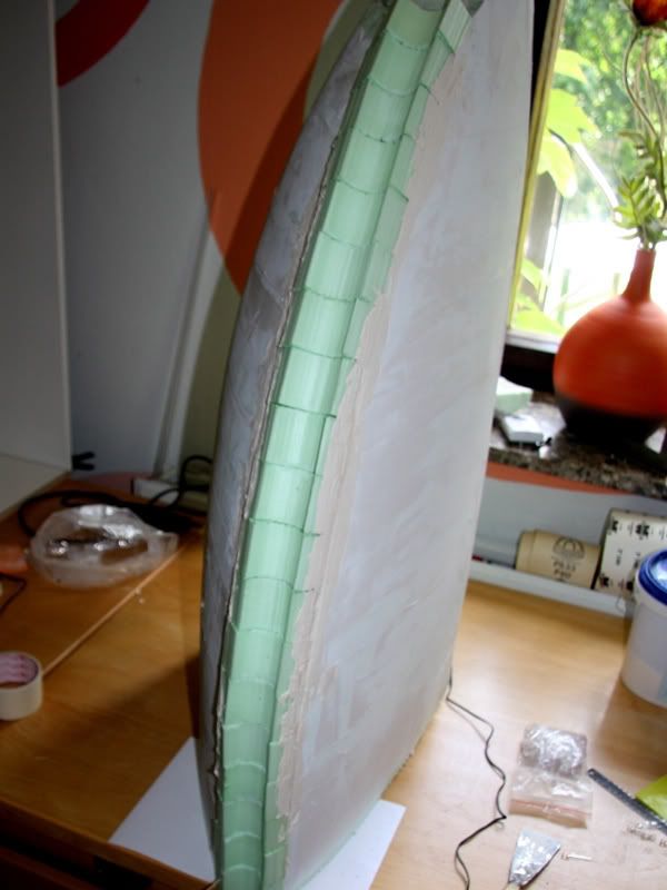
Because I swathed the tube with baking paper I was no problem to remove the tube after the filler was dry. Certainly I couldn´t find a complete smooth surface.
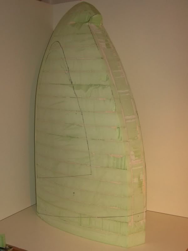
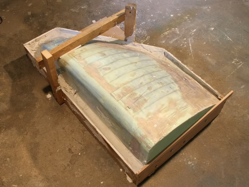
To get a smooth surface I built a kind of scraper made of Plexiglas. This scraper has on the one side a semicircle with a diameter of 4.1cm. After the first run with that scraper it looked so.
I also filled the transition.
Unfortunately I hadn´t enough time to grind the form because the filler needs a lot of time to dry.
Beside the grind- and fill work I bend the inner tube for the reservoir. For this I had to built a new form, because the radius of the old form wasn´t still correct.
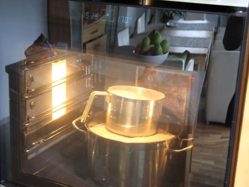
Now I built a kind of oven with a diameter of 8cm.
How you could see came the plexitube in the oven. The oven is headed with sand that got its temperature of 170°C in the baking oven before.
I fill the sand at first in the Plexiglas tube and then in the big tube. After some minutes the tube was soft enough to bend it.
Well I´m quite satisfied with the tube, because it´s almost perfect except one little bump. This bump I´ll grind out and because I´ll grind the whole tube matt it isn´t such a big problem.
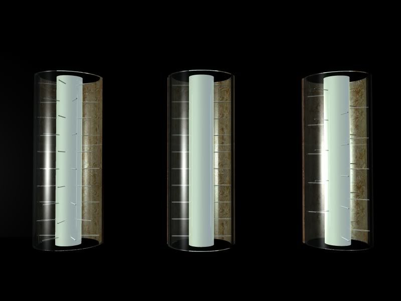
A bigger problem for me is, that I don´t know how I should bore the 0.6mm holes in the tube through that the water squirt. But maybe you could help me. Here are 3 possibilities.
So which one do you like mostly, or have you maybe other possibilities? The only condition is that holes should be bored at a line of 70cm, and in these 70cm I could only bore about 140 holes.
@OvRiDe: Oh sorry, I don´t see these other category, but I hope it´s no big problem for you to remove it. Well the thing with the title isn´t really important so you haven´t to change it.
06-16-2009, 07:02 AM
DonT-FeaR
Re: the golden sail
sweet! no1 left...
for sure
06-17-2009, 07:30 AM
tomcatt
Re: the golden sail
omg amazing !!
Definitely worth rep :-)
06-17-2009, 10:44 AM
SXRguyinMA
Re: the golden sail
Indeed, Looks Awesome!
06-19-2009, 11:24 PM
Scotty
Re: the golden sail
Very interesting and imaginative idea!
06-25-2009, 04:17 AM
D.Heiße
Re: the golden sail
Hello, I it´s time for a further update. I know more little updates would be better, but anyway I don´t find for this. Therefore you have to settle for bigger updates every week or every two weeks unfortunately.
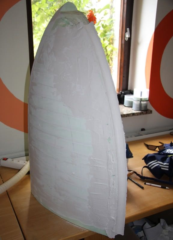
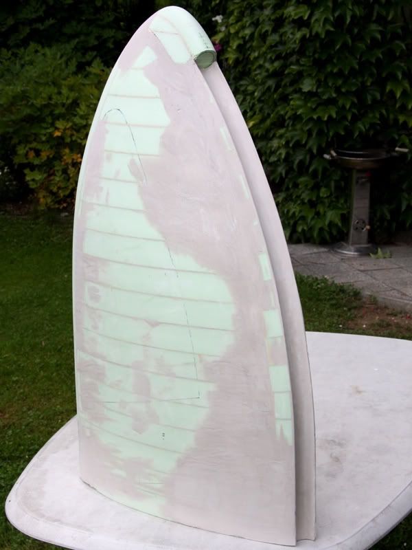
Well as might have been expected the first part of the update is about filling and grinding the positive form. After I glued the socket for the reservoir at the rest of the form I filled it with surfacer
And then I grinded it.
Ready with this I filled and grinded the front of the form, that the reservoir exactly fitted
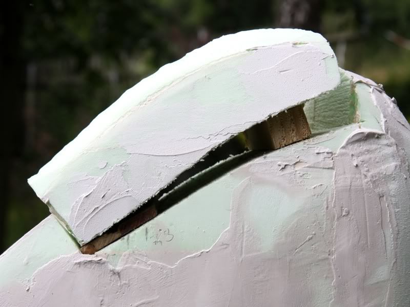
Thant he reservoir fitted I could put the peak of the form on the rest of the form
I don´t know why the peak is ca. 3cm higher than before ;-)
This gap I filled also with surfacer and after the surfacer was dry I grinded it. And at the end it looks so
Now the surface was really smooth, but because of the surfacer really absorbent, too. That means I had to seal the surface. For sealing it I decided for epoxy resin because it don´t damage the Styrodur.
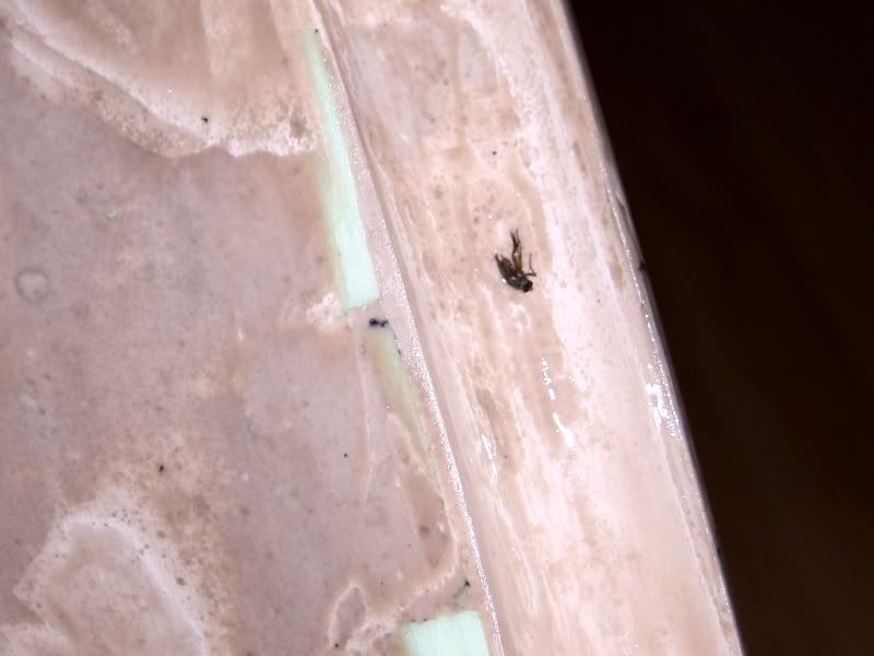
After I was ready with spreading the form with epoxy resin I hit the sack for an hour and ditched the form in the sun. But this was a little mistake from be, because than I stood up I found this picture.
Unfortunately it wasn´t only one fly that taped at the form, but rather ca. 40 mini flies and ca. 10 bigger flies.
However I had blessing in disguise, because the flies were soaked with epoxy and therefore they were similar solid how the rest. Because of this I could grind the flies very easy how the rest. Therefore it wasn´t such a big extra time, because I had to grinded the form anyway.
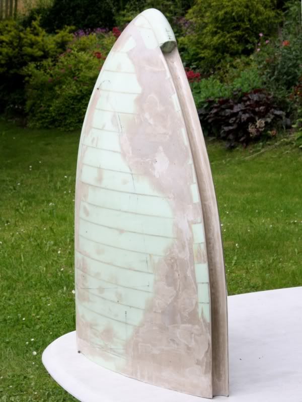
With this step the filling and grinding of the positive form was concluded. After grinding the epoxy the surface was a little bit blunt. So I had treaded the form with car polish. Ready with this some party of the form get a blue hue based on the polish ;-)
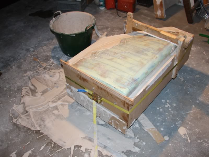
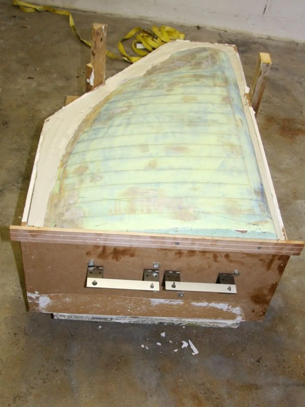
Ready with the positive form I could start with the negative. For this I thought a form made of plaster is the best thing. At first I would casted a complete form, but with a complete negative form I would have problems by laminating the form. So my plan was to made two forms, one from the right side, and the second from the left side
With this plan in my head I started with building a form in that I could put in the positive form and cast the plaster in it. I started with the form for the right side.
The edges I reinforced with architectural foam to get a better stability.
And so looked the form with the positive form in it.
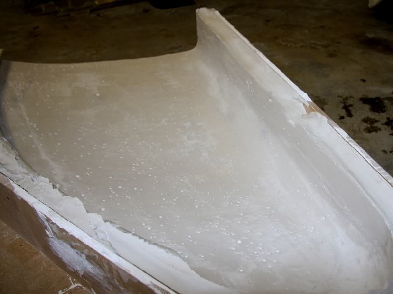
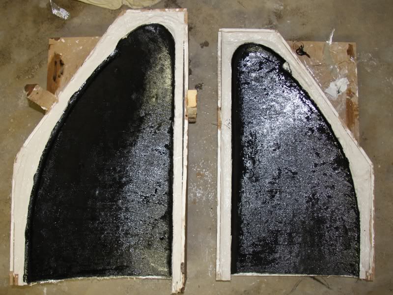
After I casted ca. 25kg plaster in the form it looked so.
Past 6 hours I could remove the positive form relative easy. Now the negative form looked how a Swiss cheese, but I think after I´ll fill it with surface it would be very smooth. And I think it´s better to have a lot of little air inclusions than few big air inclusions.
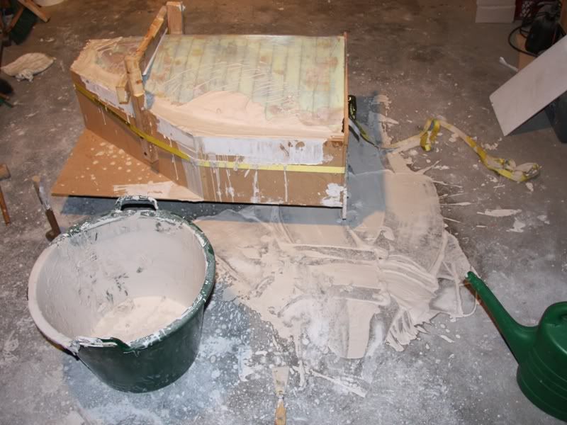
Ready with the right form I could started with the left form. At first I built the form for casting the plaster in it.
With the positive form in it, the form looked so.
And so the havoc after the casting session.
How you could see was the leaky so the plaster flowed out because of the pressure of ca. 80kg plaster ;-)
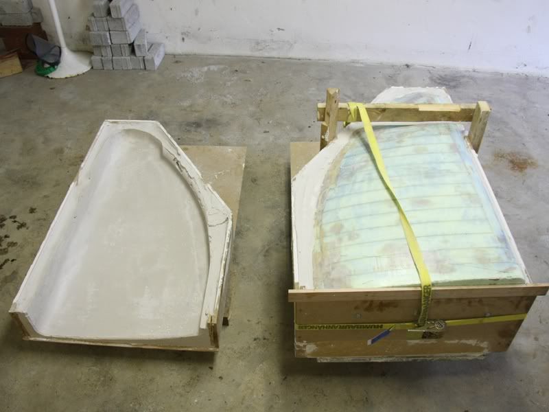
I´ll remove the positive form tomorrow, but at the following pictures you could see the two forms abreast.
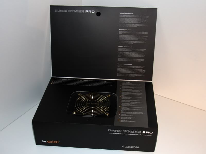
Well at least a little Hardware News, in fact I got a great packet last with the following content.
How you could see is this a Dark Power Pro 1000W that I got from be quiet. Therefore I would say a big, big THANKS to Aaron from be quiet for the great support!!!
06-25-2009, 08:44 AM
Nate Dogg
Re: the golden sail
Looking quite exciting :D
06-26-2009, 03:27 AM
DonT-FeaR
Re: the golden sail
i really like it its looking really good mate
06-26-2009, 07:56 AM
Waynio
Re: the golden sail
Go on the curve master.:banana:
Another outstanding build taking form +rep:bowdown:.
07-01-2009, 02:17 PM
D.Heiße
Re: the golden sail
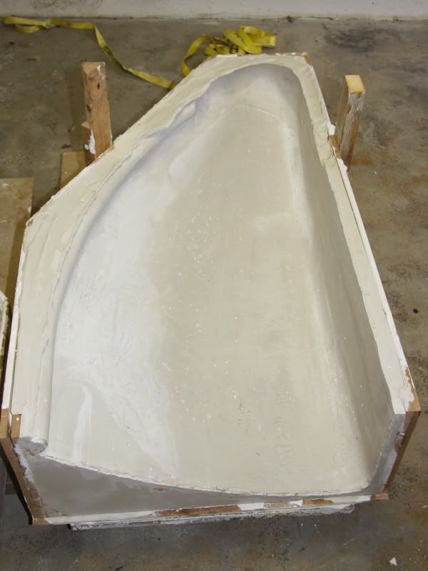
Hello, after I cast the big form with plaster and the plaster was try I could speculate about getting the positive form out of the plaster. For this I installed at first two self made grasps on the positive.
With this grasps it was really easy to get the positive out of the plaster and so I had two negative forms.
The result of the second form was a little bit better than of the first form, but only a little bit. That means there were a lot of air locks that I had to fill with surfacer.
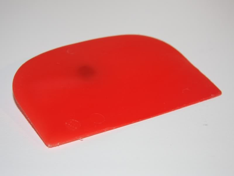
Well and so we are by the theme, because to fill a concave form with surfacer isn´t such a problem with a normal scraper, but to fill a convex form is a bigger problem with a normal scraper. So I had to look for another alternative. After I short look in our kitchen I found an ideal scraper.
This red thing made of plastic is an ice-cream scraper from the DDR that means more than 20years old. At this thing you see that you should never trash anything ;-). This scraper was ideal for the big convex surfaces, and for the tight radii I used a silicone scraper from the kitchen.
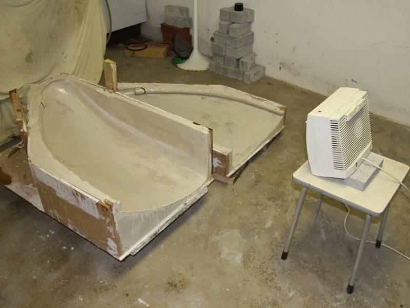
Ready with filling the air locks of the two forms I could start to seal the plaster surface with epoxy resin.
The white box is a blow-drier to accelerate the process of drying.
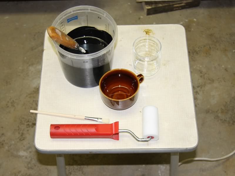
After the second layer of Epoxy I treated the form with wax to get the GRP-form easier out of the negative. Than the wax was dry I polished it and then the drama could start. At first I measured out the ingredients for the first layer.
This is gelcoat for the outer layer of the GRP-form to get a really smooth surface.
After I stirred all together I painted the gelcoat on the form with a roller.
The black color is more just for the hell of it, because the case will be varnished black either way at the end.
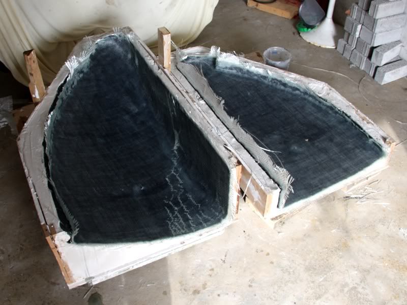
During the gelcoat dried I cut out the fibreglas mats.
Well and now I got the first little doubts because the gelcoat didn´t dried, that I wondered about. But a short internet research said me that the gelcoat haven´t dry at first, it will dry complete after the first layer of polyester resin.
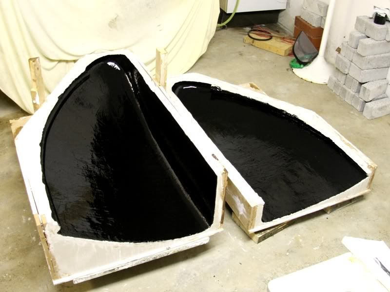
So I could continue without any doubts with the first layer of fibreglas and polyester resin.
And so looked the form after 3 layers of firbeglas.
Currently I got a real great problem. In fact I noticed that the gelcoat wasn´t dry after two days, and I haven´t had really big hopes that it will dry the next days. That means I had to change my plan.
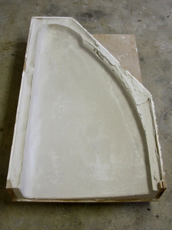
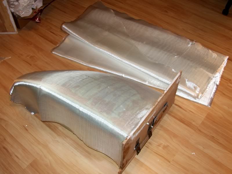
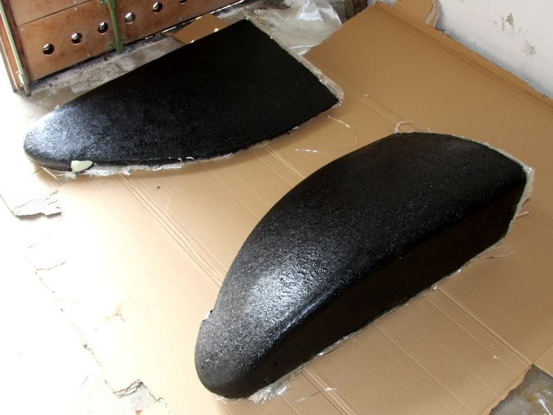
After I gave some thought to the problem I came to the decision to put the GRP-form out of the negative and then I would continue the work on it.
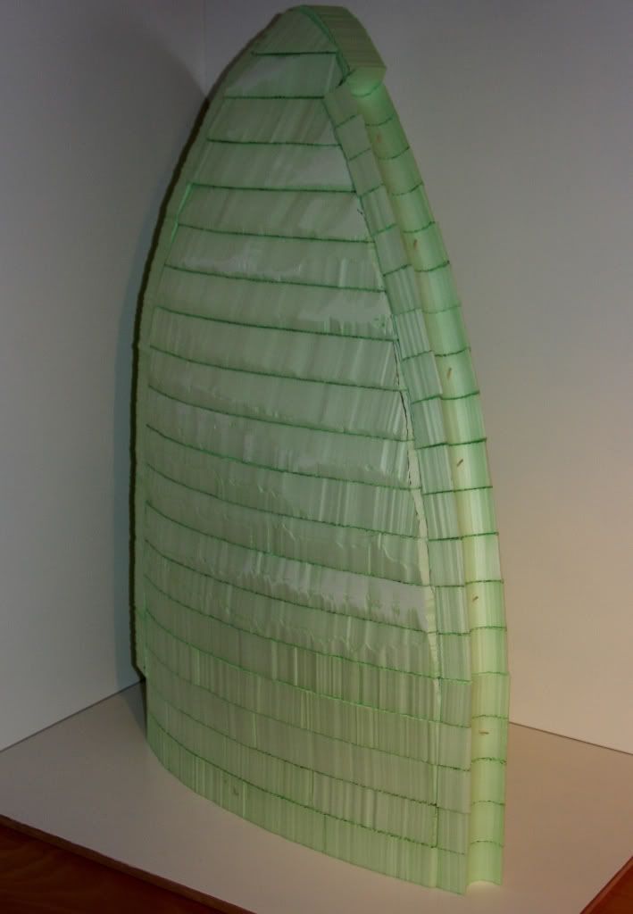
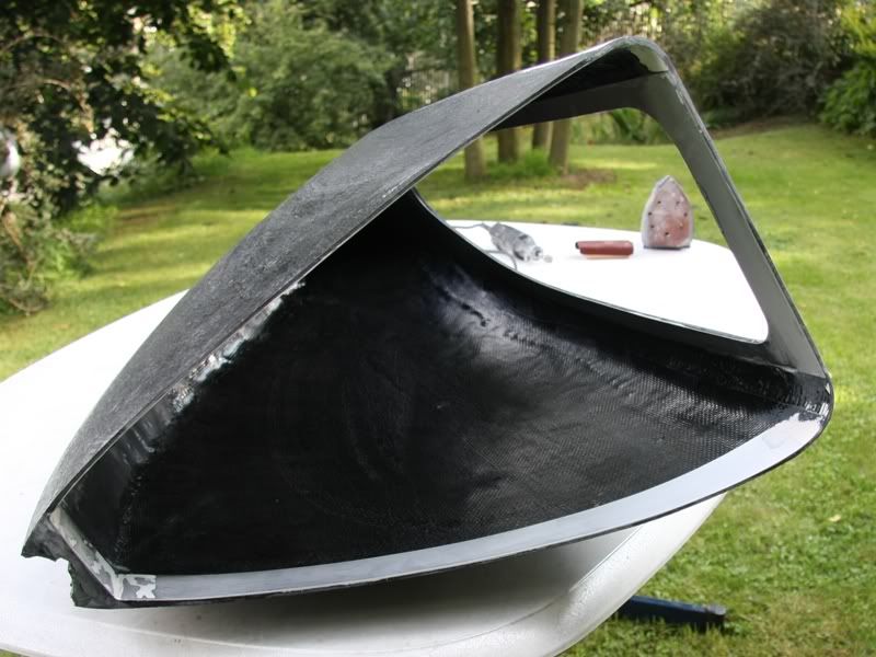
No sooner said than done and so looked the two GRP-forms.
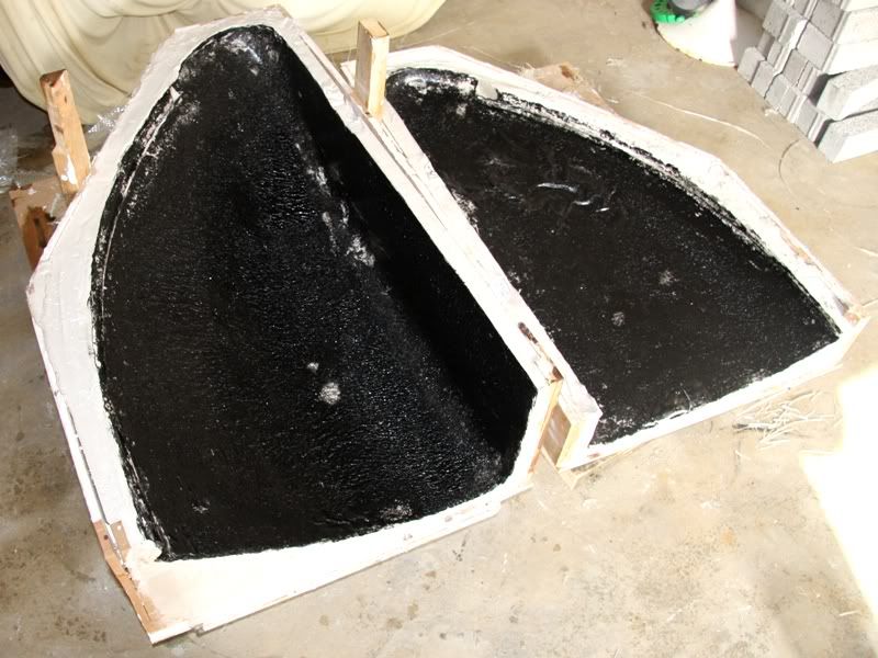
And so the two negative forms made of plaster.
I´m actually satisfied with the two GRP-form. To get a better surface I pained the two forms with polyester resin and the following week I try to put the two forms to one form together. The result you´ll see hopefully next week.
At the end I´ve one question, namely I don´t know how I should install the LEDs in the interior to illuminate it really good. So if you have a great idea how I could integrate the LEDs in the design of the PC, please let me know it!
07-01-2009, 02:53 PM
SXRguyinMA
Re: the golden sail
nice work! looks awesome. should have skipped the gelcoat and done the first layer in carbon fiber :devious:
07-08-2009, 02:05 PM
D.Heiße
Re: the golden sail
Hello, after I had to noticed that my gelcoat-action went wrong last week, I brushed the sticky surface with polyester resin. When the resin was dry I had at first a surface that doesn´t stick anymore. The surface wasn´t indeed so smooth how I want, but it was still acceptable for me.
Now I could continue with working on the two forms. At first I marked the cut edges.
To get a clean edge I used a Dremel, which I got warmly from the company Dremel. At the beginning I wanted to use a angel grinder, but I´m happy that I scraped this idea ;-)
After the two form were cut I washed them.
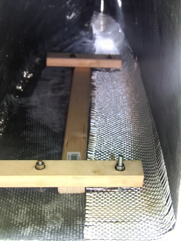
And now I stand in frontof the question how to get these two forms together to one. Beside the fact that the backside had to be completely flat it was very important, too that the tube in the front fitted exactly at the end. Therefore it was inevitable to use the tube during the glue-process. That the tube wouldn´t be damaged I wrapped it with kitchen foil.
Ready with this I could adjust the two forms. For this I screwed on the forms with the backside on a flat board made of wood. Therefore I could be sure that the backside would be really flat at the end. After this I inserted the tube a fix it with cello tape
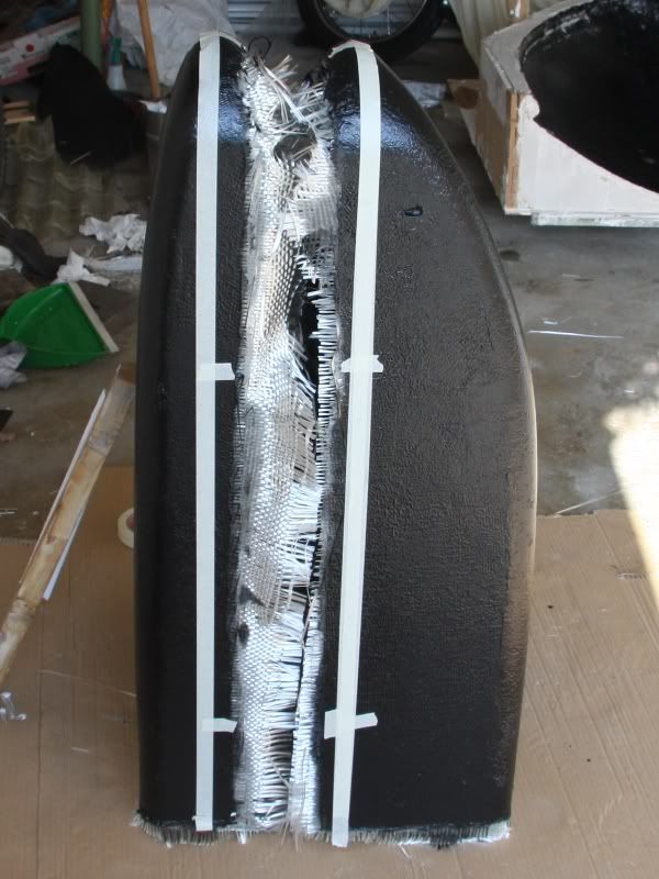
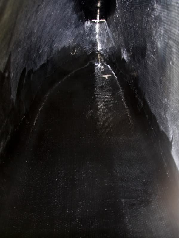
Now I turned the board with the form, because at first I would stick the front edge together. At first I laminate on layer GRP over the slot. After it was dry I touched a pulp made of polyester resin and fiberglass chips. This pulp I daubed at the inner surface of the front edge.
Over the dry pulp I laminate on layer GRP to get a smooth surface.
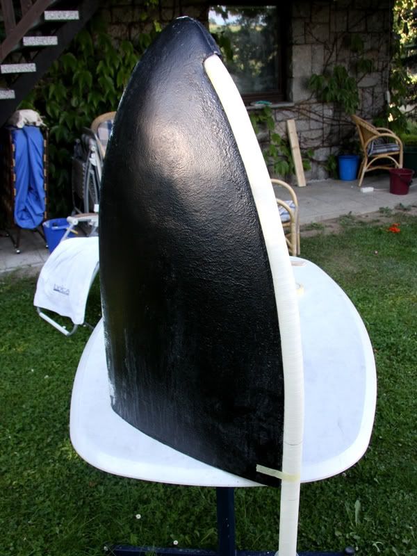
And now the sail with the tube in the front looked so.
After the front edge was glued I could devoted to the backside. For this a had to change the stretch appliance, because with the first version I couldn´t glue the whole edge
Ready with this a laminate at first the right side. When the GRP was dry I could unscrew the stretch appliance, because the sail couldn´t change his form anymore. At least I laminate on thin GRP layer at the inner surface of the backside.
After the edges were all sticky a reinforced the laterals with GRP, because in my opinion they were to flimsy.
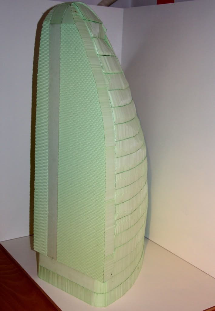
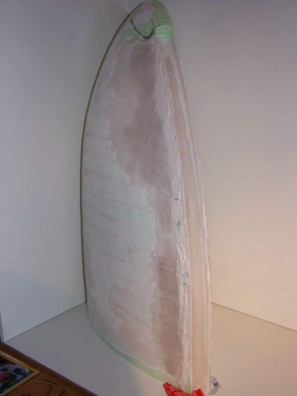
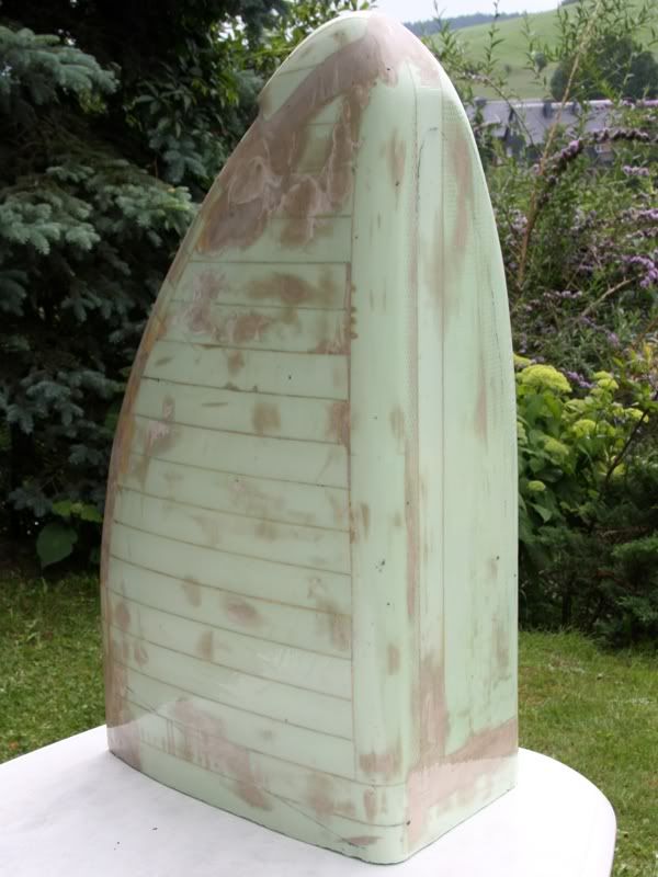
When the GRP form was solid enough I could start with mark the things I had to cut out of the form. At the following pictures you´ll see what I´ll cut out next weekend.
I´m actually really satisfied with the form and hope that I´ll have enough place for the hardware in it.
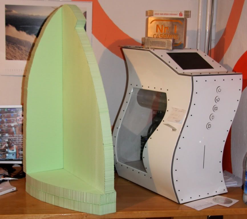
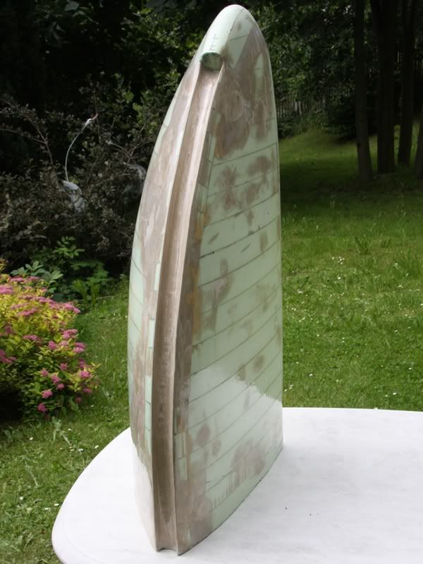
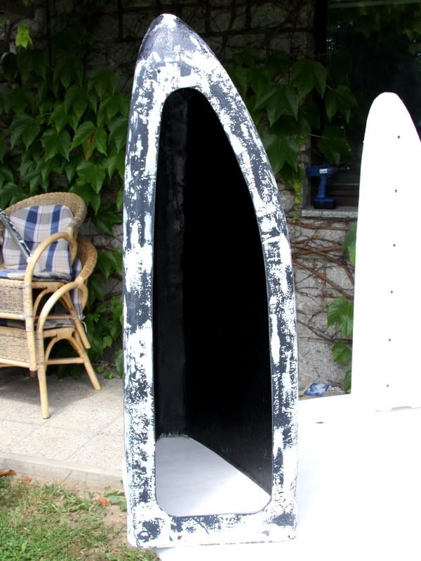
To get a better imagination about the dimension of the golden sail I put the form besides the sinecurve (a PC that I build 2 years ago). The sine curve is ca. 70cm high but how you could see at the following pictures this PC would be a little bit bigger
if you consider that under the sail will come a 7cm high socket made of high-grade steel you´ll know that the PC would be really big.
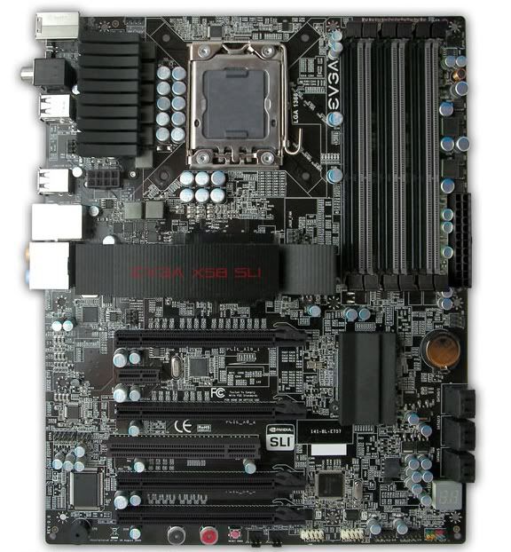
And now we are unfortunately at the end of this update :-(. Well one little hardware news I have for you. Namely I won´t use a Asus Board, but to 95% this hot thing.
@SXRguyinMA: I think the carbon would upstage the 24 carat gold. And so the sail would be true black at the end. But maybe I´ll use carbon in one of my next cases ;-)
07-09-2009, 01:53 PM
SXRguyinMA
Re: the golden sail
looks awesome :up: nice job!
I used carbon in my rockin case project...speaking of which I need to finish that thing lol
07-15-2009, 05:08 AM
D.Heiße
Re: the golden sail
So after the weekend is over it´s time for a new update.
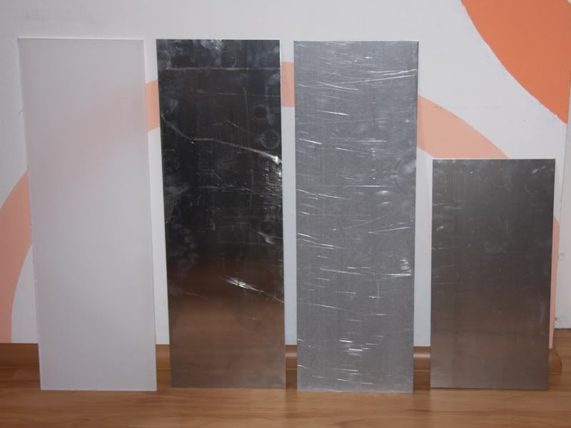
The weekend started with a small but mighty consignment of aluminum and Plexiglas
That´s 8mm Plexi and 3mm, 2mm, 0,8mm aluminum.
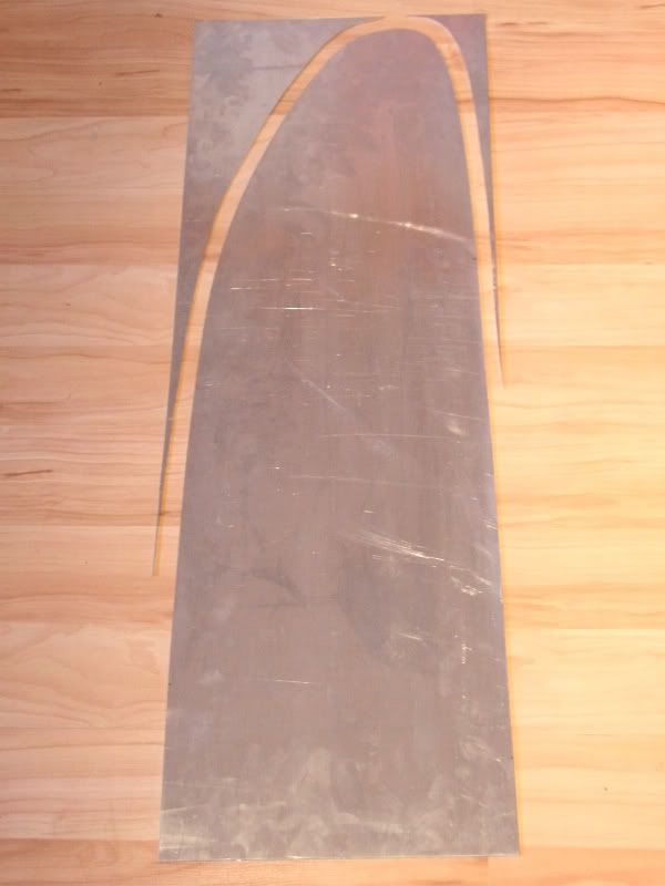
The 0,8mm aluminum I used to get a really plan surface at the inner side of the backside. I know another alternative was to grind the GRP, but I thought it would be too troublesome and inaccurate.
After I took the measurements from the GRP form I could start with cutting out the aluminum, and after with filing and grinding.
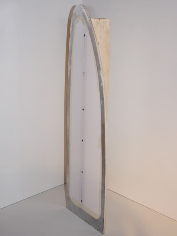
Ready with this I could bother one´s head about pasting the instable 0,8mm frame made of aluminum at the GRP really plan.
At the end I decided to glue the frame at the 8mm Plexiglas plate, but not absolutely secure, because after the glue was try I had to remove the Plexiglas plate. Moreover I screwed on the plan piece of wood at the Plexiglas to get a better handling and any more stability.
To stick on the frame exactly I marked the position at the GRP and then I brushed polyester resin on the GRP. Than the resin was everywhere, where it should be I pressed the frame with the Plexiglas and the wood at the resin and ballasted it with juice bottles.
After the resin was dry I removed the Plexiglas plate with the wood. This proceed without any problems. Now I could start with cutting out the hole in the Backside with the aid of a Dremel.
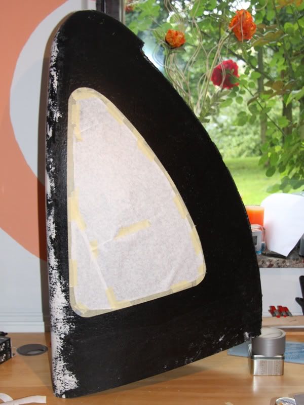
To get an accurate edge I treated it at first with a file. Unfortunately the aluminum frame removed at two sites during I worked with the file. Because of this I put it away a take my Dremel. At the following picture you see the big hole in the backside after I had grinded it.
How you could see, too, I started with filling the radii at the backside.
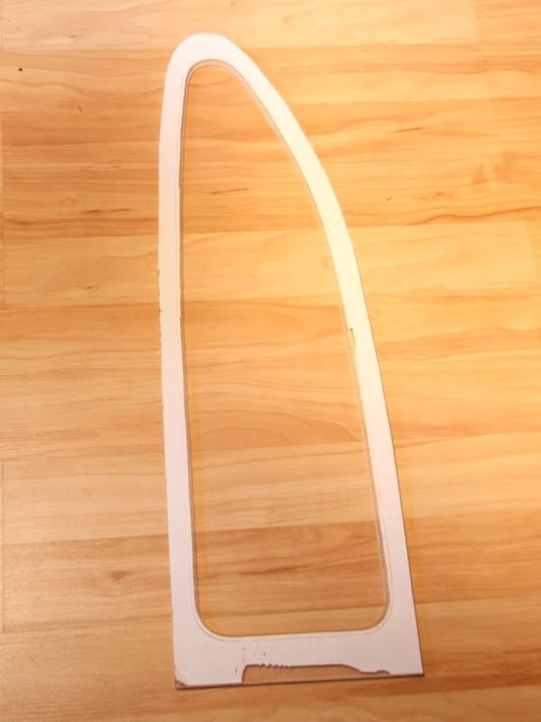
After the hole was nearly perfect I could started with Plexi plate. This plate is for the lightning of the backside. At first I cut a hole that was 8mm smaller than the hole in the backside in this plate. The 8mm at each side I needed for shaping a 8mm radius on it.
In the outside of this plexi frame I´ll bore about 100 holes for LEDs in it. I know 100 LEDs are a lot of, but I needed so much, to get a very consistent lightning.
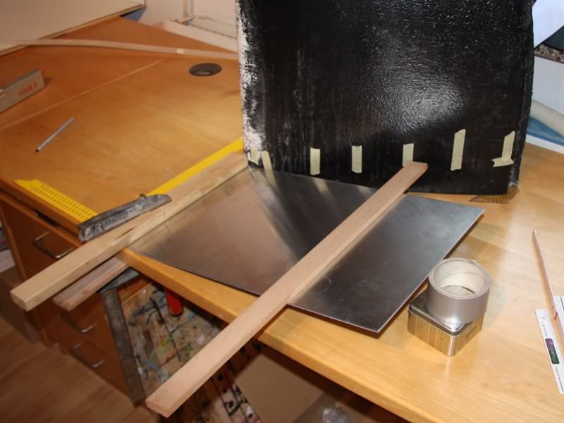
After the Plexiglas was adapted I could start with the 2mm aluminum plate that should be the back panel of the case. At first I cut it out and filed it that I adapted exactly.
In this alumium I´ll bore a lot of holes (>100) through that the hot air from the case will stream out. Moreover I´ll cut and file the holes for the mainboard blind and the slot blinds.
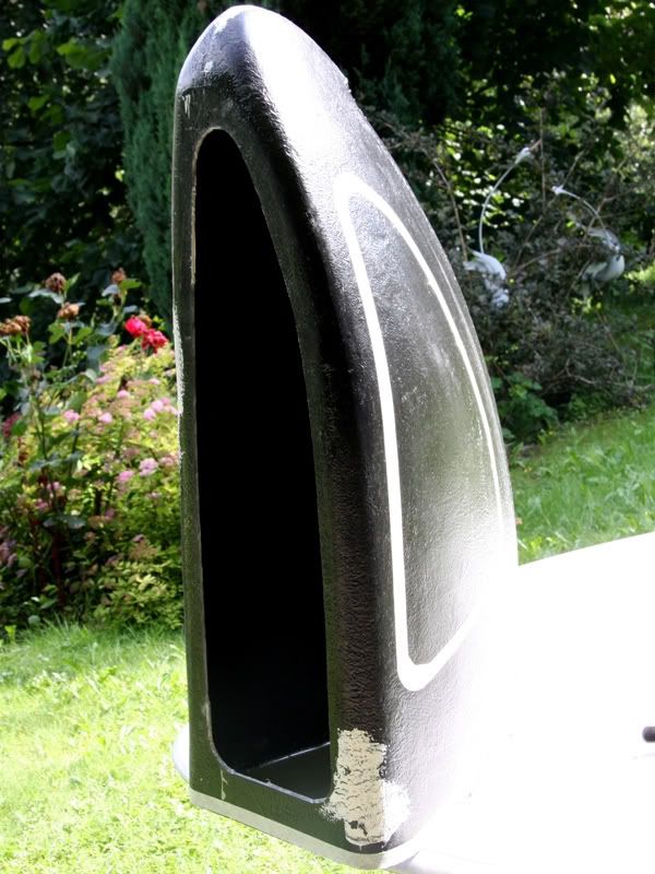
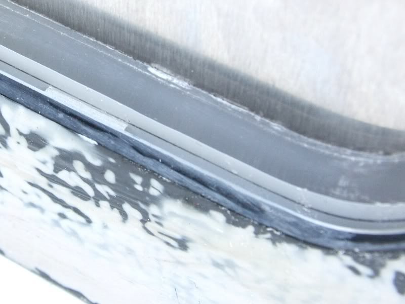
At the following two pictures you see how the backside will look at the end
At first it´s to say the radius at the Plexiglas isn´t final, that means I´ll grind it exactly later. Additionally the piece pasteboard that is between the GRP and the Plexiglas will be replaces by a frame made of black cellular rubber with a diameter of 2mm. That rubber will equate irregularities of maybe to 0,5mm, I hope.
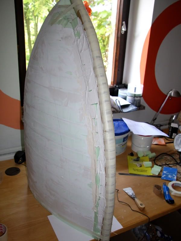
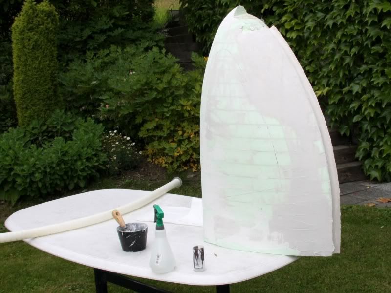
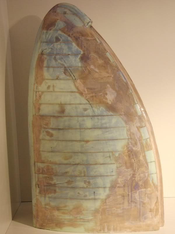
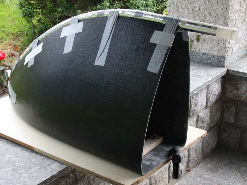
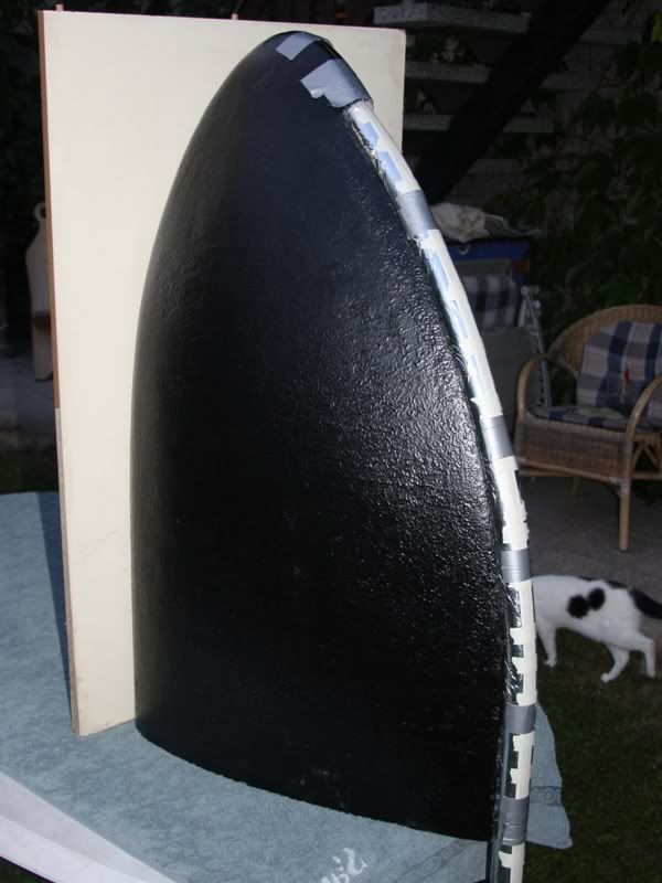
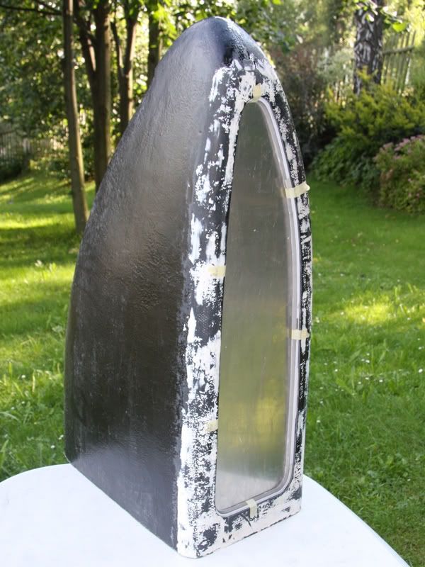
Well and now we are unfrortunately at the end of this update. At least I´ve a picture for you that shows the GRP from with the tube in the front. I hope I´ll have enough time the next weekend to adapted the tube exactly with surfacer to the GRP form.
07-15-2009, 07:44 AM
SXRguyinMA
Re: the golden sail
lookin good my friend, lookin good :up:
07-15-2009, 11:39 AM
tomcatt
Re: the golden sail
looking very nice !! love your work
07-16-2009, 07:44 AM
Waynio
Re: the golden sail
Really coming along now :), this is going to be fantastic, very original work :bowdown:.
07-22-2009, 02:41 AM
DonT-FeaR
Re: the golden sail
looks great :P
07-24-2009, 06:10 PM
D.Heiße
Re: the golden sail
Well a little bit late the update for the last weekend, but better late than not at all.
Last weekend I started with chamfering the aluminum for the bottom. After this I marked the angel from the aluminum plate to the GRP form
I bend at first the aluminum and after I marked that angel to the form, because it´s easier to cut the GRP form in the right angel, than bending 3mm aluminum in the right angel.
Ready with marking the angel at the form, the form looks so.
Now I could crop the wedge with the Dremel. Certainly the cutting edge wasn´t perfect after cropping. So I had to file and grind the edge, but the rework wasn´t really much. During I cut and grinded the form a lot of swarf dropped at the form. This swarf wasn´t really good for the next work stages so the GRP form got a hot shower.
After the form was clean I could reinforce the cutting edges with a 0,8 aluminum stripe. Certainly I did it after cutting and not before like at the backside. Moreover I didn´t use polyester resin to stick that stripe at the GRP, but Rotabond 2000.
Thant he Rotabond was dry after 3 hours I could fill the interfaces with surface. I know, nobody would see this after the PC is ready, but my aim at this project is to make it nearly perfectly.
Now I could work again at the aluminum bottom plate, because the plate was indeed bend but not cut into dimension. So I put the GRP form with the aluminum stripes at the bottom plate and marked the dimension with a pen on it.
After cutting and grinding the plate fitted exact at the first dry. Unfortunately to exact, because after vanishing the case it wouldn´t fit, so I grinded of everywhere a little bit more.
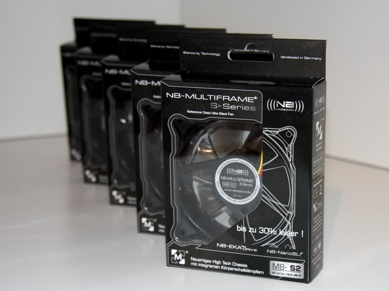
Ready with the aluminum plate for the bottom I could give thoughts to the things that will come at the bottom and above all where. For this I took at first the Noisblocker Multiframe MF8 S2, that I got warmly from the company Noisblocker.
These fans I put at the plate to see how many place I´ll have at the end, because beside the 80mm fans 2 Multiframe MF12 S2 fans, 2 Freezone Elite radiators, one Laing DCC Pumpe, one be quiet Dark Power Pro 1000W PSU and maybe some other things had to find place their place at the bottom. Because it isn´t really little I decieded to make the inner bottom a little bit higher to 20cm. Because of this the window will have following measures that you could see at this picture.
With the final measurements in my head I thought to the problem how I´ll fix the inner bottom that you could see at the end through the window. Moreover the back panel had to be connected with the bottom, and this exactly in a 90° angel.
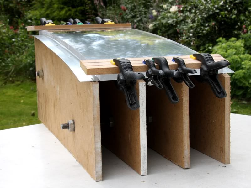
Because I thought a lot of you wouldn´t understand my explanation here 2 pictures.
Here you could see the 10mm plate made of Plexiglas, that I heated up in the oven to 185° and after it was really hot and soft I bended it over a form.
After the Plexiglas was bended I cut it and grind it. Than the Plexiglas fitted perfectly I screwed it with M3 screws at the bottom.
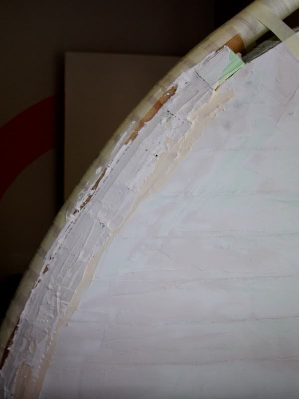
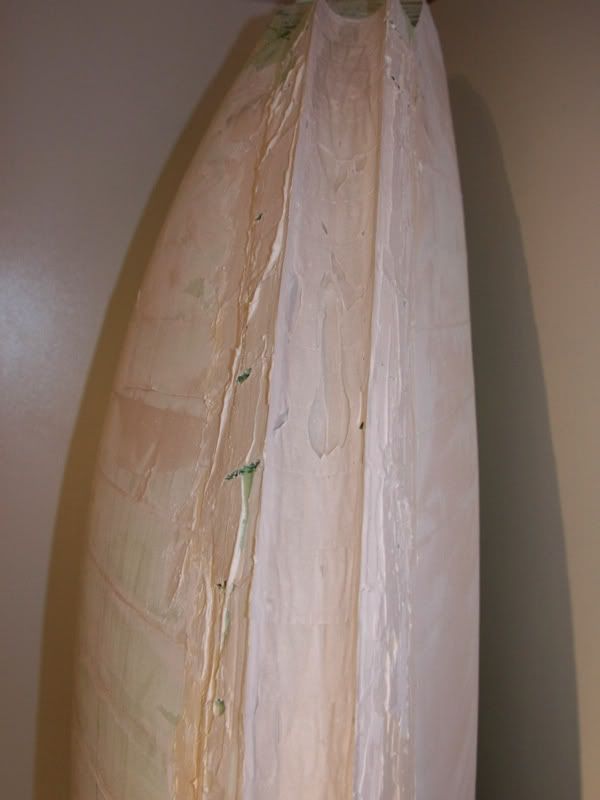
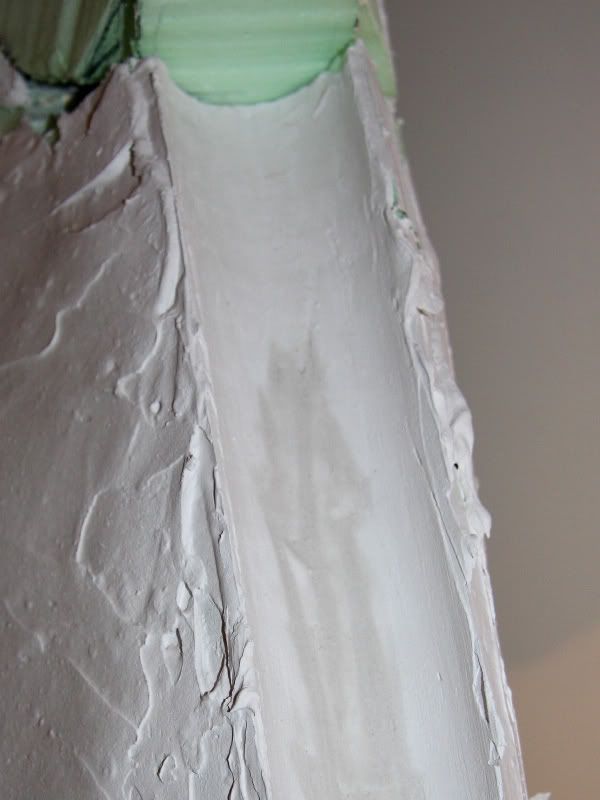
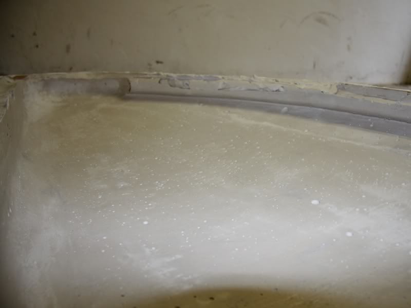
Naturally this wasn´t all I made the last weekend, because I started with adapting the tube in the front exactly.
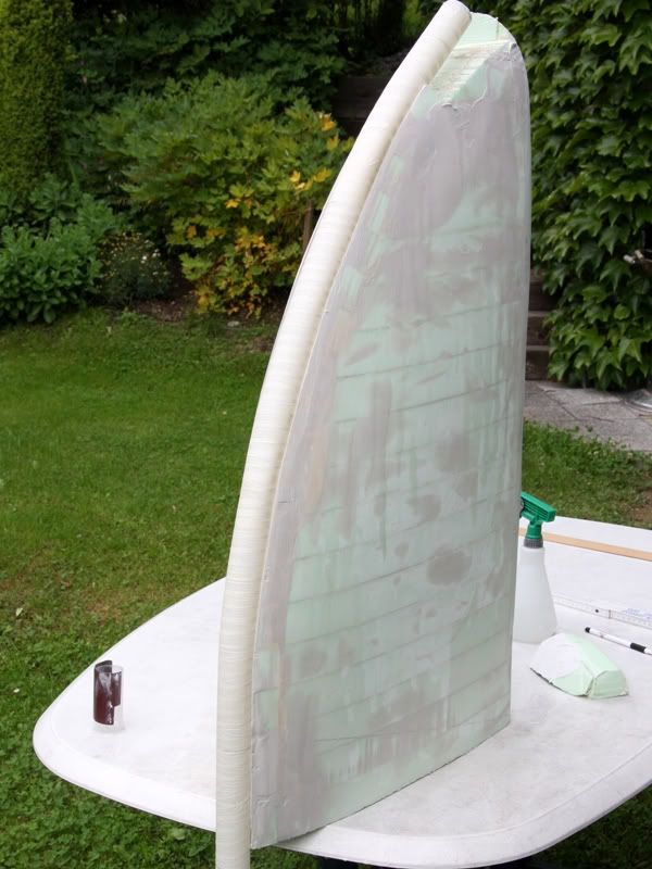
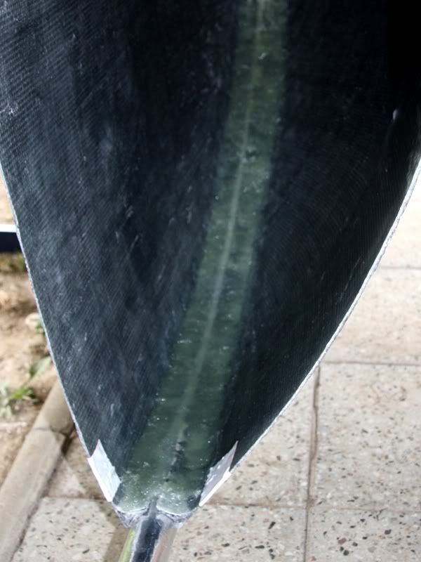
For this I wrapped the tube with baking paper and after I pressed the tube into surfacer that I put before in the immersion at the front. Additional I filled the sides with surfacer and after it was dry I could started with grinding. In my opinion the result is quit good.
.
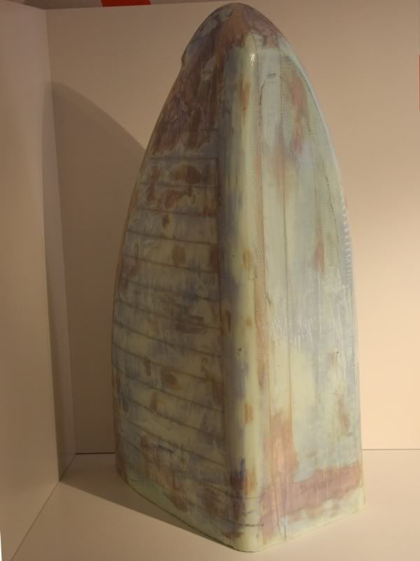
Maybe some people noticed at the last two picture that the white surfacer looks better than the black GRP, not only that the surfacer is really smooth in contrast to the GRP. In my opinion the color white is really impressive. Because of this I decided to varnish the case white instead of black.
In my eyes the sail get´s a optical lightness with the white color. And because the sail is still really big for a PC the lightness is good for the general impression at the end.
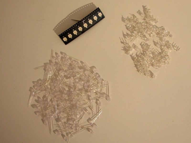
Last week I got also a package from PUR-LED with the following content