Re: I promised I'd post it. My 924 project (pic heavy)
Quote:
Originally Posted by
CorsePerVita

Altec is spot on. You don't want glass smooth. I know that sounds counter-intuitive, but the best part of port and polish is getting rid of the impurities that came in the head and intake manifold from the factory (as you said, rough spots, nasty edges, metal pieces from casting sticking out). Basically think of it like fluid dynamics, while you want good flow (which is improved by taking out crap imperfections out of stuff) you also have to keep in mind that you want good atomization and mixture. A rough to the touch finish as altec has mentioned achieves that because a perfectly smooth service can leave the fuel on the wall of the runners.
I recall seeing a really cool diagram that explained the phenomenon really well. Basically there was a tube that showed the flow of water through a pipe. On the walls of the pipe (the perfectly smooth area) the water flowed the SLOWEST, towards the middle of the pipe the velocity of the water was the FASTEST.
Now.. change the water to fuel. What do you want fuel to do. You DO want it to mix with the air. What do you want it to NOT do? Fail to atomize (turn into droplets, come together). If you get a glass smooth port and polish the fuel tends to bind together, become droplets or run slowly along the wall instead of going where they need to.
It's been shown that a semi-rough finish will result in better atomization/breakup/mixture of the fuel and better flow. It of course is most crucial for such a finish where the fuel actually enters. If you have an intake manifold that for instance mixes fuel (injector actually is near the valve) then it's a different story. However, on a setup like mine where the runner mixes the fuel up towards the ITB, the finish inside is crucial.
I thought on a fuel injected engine, the fuel injectors sprayed that s@#t straight into the cylinder tube deal itself, and the intake manifold just delivered air to the intake valve deals?

Re: I promised I'd post it. My 924 project (pic heavy)
Quote:
Originally Posted by
Twigsoffury
I thought on a fuel injected engine, the fuel injectors sprayed that s@#t straight into the cylinder tube deal itself, and the intake manifold just delivered air to the intake valve deals?
That would be direct injection. Whole different animal. Most injected engines spray the fuel into the manifold, most do it close to the cylinder head.
Re: I promised I'd post it. My 924 project (pic heavy)
Quote:
Originally Posted by
msmrx57
That would be direct injection. Whole different animal. Most injected engines spray the fuel into the manifold, most do it close to the cylinder head.
Yep. Direct Injection on gassers is still pretty new in production vehicles. Diesel engines on the other hand have been using it for a while.
Like msmrx said, normally you have a injector per cylinder, or some times a couple very large injectors in the throttle body (Old TBI setups).
What is interesting is the million different ways they control them... Some are very basic, firing half the injectors at a time, and some fire just one injector at a time.
I don't know to much about ideal porting for DI setups.
Re: I promised I'd post it. My 924 project (pic heavy)
it's a 302ci 5.0L Windsor V8 (1986)
Same engine as the fox body Mustang's. I do think its direct fuel injection. It's got Fuel rails?
lincoln
The intake manifold is backwards in design, but functions the same on a lincoln. I'm pretty sure its direct injection (i remember a badge of some type saying that) but i'll ask again today.
Re: I promised I'd post it. My 924 project (pic heavy)
The 5.0 used a sequential fuel injection. Not a direct injection setup. The supercharged example in your post shows it best. Those gold colored cylinders going straight down into the intake, with a blue rail above it is the injectors. The blue piece is the fuel rail.
A direct injection setup has the injector in the combustion chamber. If you look at the cut away you posted earlier, the injector is after the intake valve in the head. On the 5.0, it is before the intake valve in the intake. :)
Re: I promised I'd post it. My 924 project (pic heavy)
Quote:
Originally Posted by
altec
The 5.0 used a sequential fuel injection. Not a direct injection setup. The supercharged example in your post shows it best. Those gold colored cylinders going straight down into the intake, with a blue rail above it is the injectors. The blue piece is the fuel rail.
A direct injection setup has the injector in the combustion chamber. If you look at the cut away you posted earlier, the injector is after the intake valve in the head. On the 5.0, it is before the intake valve in the intake. :)
Oh well that's cool as hell (learn something new everyday)
But would the polish still matter if its a sequential fuel injection?
The hells the "real" difference between the two by the way? just efficiency?
Re: I promised I'd post it. My 924 project (pic heavy)
For a sequential fuel injection, polishing isn't necessary, or advised for the reasons mention before about mixing the fuel. The best thing you could do for the intake is smooth out any rough casting using a bur bit on a die grinder, and some rough sanding drums.
However, you can polish the hell out of the outside!
You hit the nail on the head about the difference between DI, and others. It is more efficient. But, more expensive. More R&D, a more complicated injection system, and much beefier injectors to handle cylinder pressures.
Re: I promised I'd post it. My 924 project (pic heavy)
Quote:
Originally Posted by
altec
You hit the nail on the head about the difference between DI, and others. It is more efficient. But, more expensive. More R&D, a more complicated injection system, and much beefier injectors to handle cylinder pressures.
That sounds like more expensive replacement parts, and a less reliable engine.
Well okay, were going to at some point in the future take the top end off and clean out the 185,000 miles worth of deposits he's pretty sure is all along the inside.
Re: I promised I'd post it. My 924 project (pic heavy)
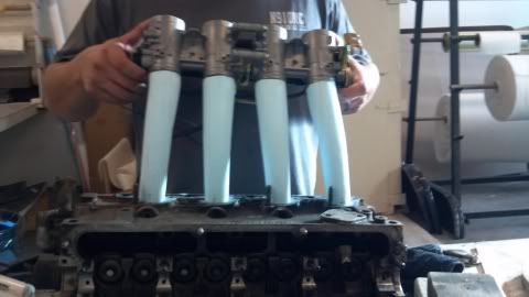
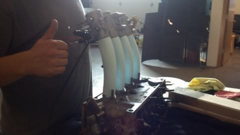
So the actual part where the manifold will bolt is apparently being cut out of aluminum. They've apparently finished that part. The mockup they had last time I saw was quite rough. They've now shaped the runners to fit to the manifold. Here's a pic as a teaser.
They got the angles correct and even got the length where I want it. The last time I saw it, the mockup was rough and still held together by sticks, so I'm happy to see they got the shaping finished.
My understanding is that from here they'll make a way to mold it and then start on the tubes and be finished shortly.
Re: I promised I'd post it. My 924 project (pic heavy)
Neat! What are those forms for the runners made of? Foam?