crenn, the servo arm measures 5/8" from center of mounting hole the the outermost mounting hole

Printable View
crenn, the servo arm measures 5/8" from center of mounting hole the the outermost mounting hole
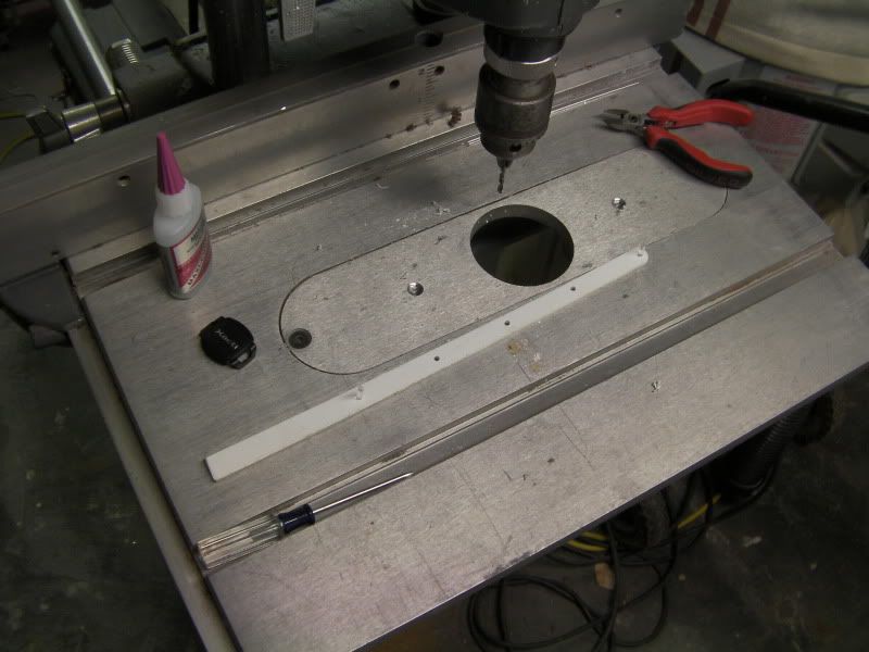
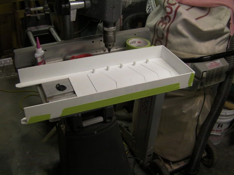
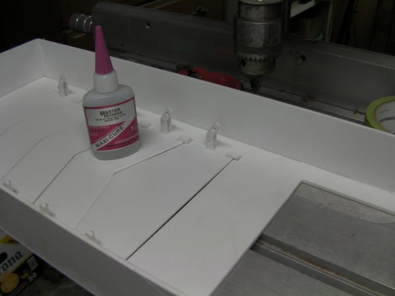
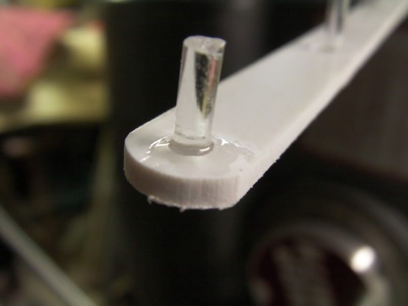
Smallish update!
I did all the needed sanding to get the fins to not catch on each other anymore, they all open and close smoothly now. I also added small tabs to the bottom of each one so they will only close until they're flush and won't more any farther. This will also alleviate any play in the linkage that might keep one fin open a crack while the others are closed.
I also finished gluing all the mounts. Now I'll just have to do some finish sanding on the glue and finish sanding with higher grits on the fins to take out the scratches before everything gets painted.
Hopefully this weekend I'll get to finish all the mounts permanently with the acrylic pins glued into place, and get the servo mounts made and the servo mounted. That's all for now!
Wow, this project just fuels my love of moving parts! Long live mechanical motion, down with the boring solid state! I'll take the linkage on a six-pack carb setup over electronically-controlled fuel injection any day. Cases just don't have enough $#!t that moves. :D
Just outstanding work, +rep!!
lol thanks!!
Update time!
The original actuator arm I had made broke because I made the walls around the holes too thin. So I cut a piece and made myself a new one
Then the 3rd side was glued on
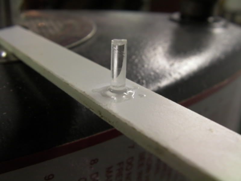
The 1/8" acrylic rod pieces were glued into their respective holes in the actuator arm
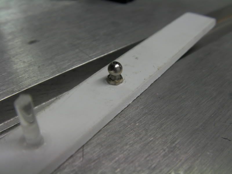
I drilled a small hole to thread in this ball stud
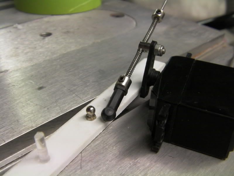
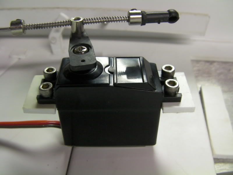
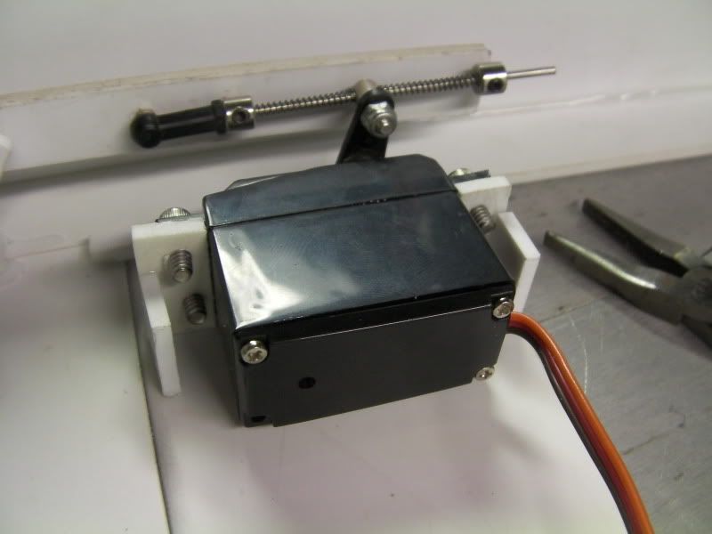
Now I had to swap out my micro servo for this standard one because the linkage I wanted to use was too big for the small arm on the micro servo
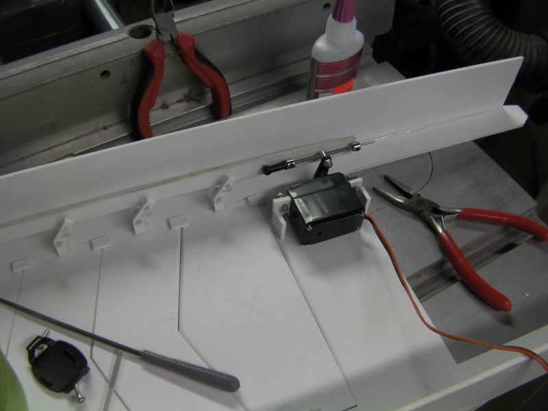
I made some servo mounts
And all glued up
That's it for now while the glue sets up. Tomorrow or Thursday I should be able to hook this puppy up and test it! The linkage I used was from the forward/reverse servo from my old Traxxas T-Maxx. It's got 2 springs that should help keep the louvers shut as I can have the servo go a little past the point where they close and it'll hold them shut nicely.
Once it's all tested, all that's left is to finish gluing up the rest of it, make some mounts to mount it to the case, then bondo it up, sand it, and paint it!
Very nice. Looks like there's plenty of space for the larger servo too.
How come you moved to a ball linkage if you mind me asking? I don't think that was in the original design.
Top notch my friend. Looking great! I can't wait to see it in action.
Looking awesome! This is going to be one of the coolest PC + Arduino mods to date!
Thanks! Yes there should be plenty of space for it. The next step is to temporarily mount the 2 top fans and place this on and check all clearances and see how far open the louvers can go before they hit the fans, if they hit at all.Quote:
Originally Posted by x88x
TBH I never really had a set design in the beginning as far as hooking the servo the the actuator arm. I was planning on building the assembly, then mounting the servo wherever possible and using whatever linkage needed to make it work. I've got a ton of old R/C car stuff laying around (hence this servo and linkage) that made that part easy. I ended up needing the ball socket part because it was going to be nearly impossible to get the servo mounted exactly how it needed to be to hook it directly to the actuating arm. This way allows a little more flexibility in servo location as well as some give in the whole setup, which will be needed once I get the system up and running to properly calibrate the servo to the temp readings.Quote:
Originally Posted by crenn
The linkage was from the forward/reverse selector on the transmission and that particular servo was a hi-torque one that was used in the steering. I had to swap it into a new case and solder on new connector and wiring (R/C nitromethane fuel doesn't do plastic any good)
Thanks! Hopefully just another day or two when I've got a free sec to plug it in!Quote:
Originally Posted by OvRiDe
Thanks CJ!!Quote:
Originally Posted by Oneslowz28