Re: Off Road Electric Kick Scooter Build
Quote:
Originally Posted by
TLHarrell

Not sure about the geometry of the front end...
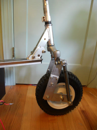
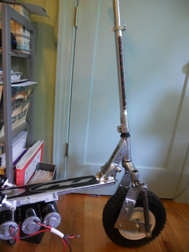
After a lot more thinking about how I could relatively easily change the fork geometry to improve handling, I went for it and rebuilt the fork. Steering feels much better now, and I did not have to sacrifice any suspension travel, because I just increased the clearance.
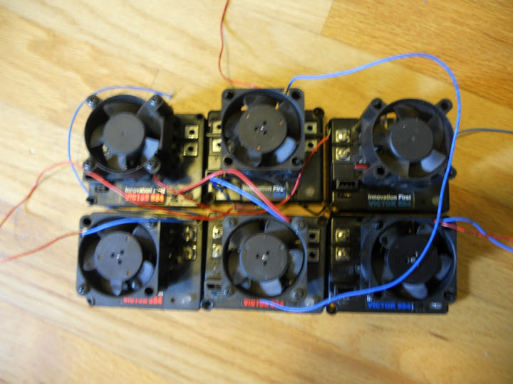
For anyone interested, here are the motor controllers. I think I may go ahead and take x888x's suggestion and try to sell these off to get a proper vehicle controller like a mini Kelly.
Re: Off Road Electric Kick Scooter Build
I posted the controllers on ebay, if anyone happens to be building a robot, or something else that might need a few big h-bridges. Heck, you could even hook one of these up to an arduino and and all your case fans, and have an absurdly overpowered fan speed controller.
http://www.ebay.com/itm/IFI-Victor-8...#ht_500wt_1361
Re: Off Road Electric Kick Scooter Build
That steering geometry looks a whole lot better now. Now all you need is a good motor driver and you're ready to faceplant with the rest of the kids. I wouldn't ride one unless I was wearing a football helmet and full riot gear.
Re: Off Road Electric Kick Scooter Build
4 of the Victor motor controllers sold already, which should cover one of these:
http://kellycontroller.com/kds72200e...ler-p-762.html
Should be more than enough power, at 120A continuous at 55.5V, 200A peak, and all three motors in series.
Re: Off Road Electric Kick Scooter Build
I can't wait to see some video on YouTube of your first ride. It's gonna be epic.
Re: Off Road Electric Kick Scooter Build
Heheh, sound good. That should give you a lot more oomh for less $$. I'm actually considering picking up one of those controllers to play around with for my little scooters.
Re: Off Road Electric Kick Scooter Build
I put in the order to Kelly a few days ago, so I should have the controller and a throttle pretty soon.
All the progress on this so far has been towards getting the scooter to actually move. But an equally important aspect of the build is how, once the scooter gets moving, I will be able to stop it.
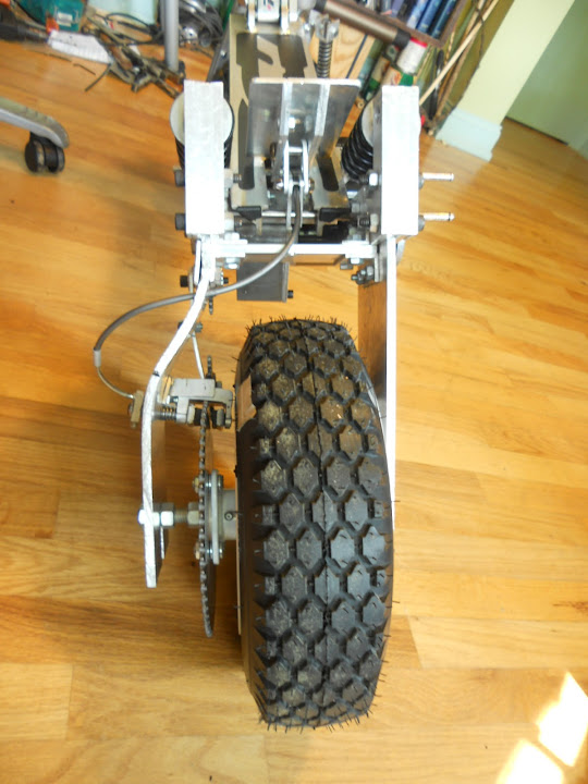
The geometry of the wheels I am using does not accommodate the addition of rim brakes, so I decided to use the large sprocket on the back wheel as a disk upon which disk brake calipers could clamp. After all, brake disks really are are large circular pieces of metal bolted to wheels, so using a section of the sprocket that did not have chain around it seemed an ideal place to fit a brake. I had two main problems with this plan. First, as x88x pointed out, due to the chain tensioner I have an absurd amount of chain wrap around the large sprocket. This leaves only one spot where I could fit a brake caliper. Second, no one makes a disk brake caliper that would fit in the available space (or around a sprocket either, for that matter). Here's what I came up with.
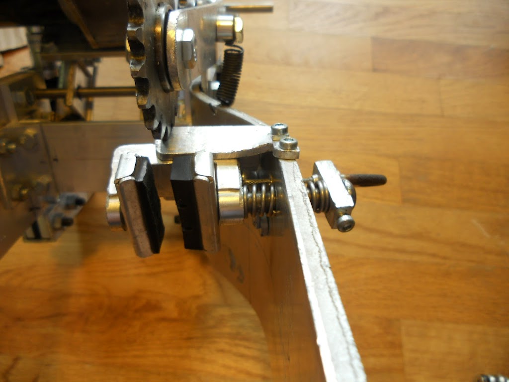
Here is the actual caliper. The pads are standard road bike brake pads. The inner (left) pad is fixed to the large "U" shaped block of aluminum, which slides within the bit of U channel aluminum that is bent and screwed to the frame. The right brake pad is connected to the rod that passes through the springs. The two part spring, divided in the middle, ensures that when the brake cable (visible just above the spring) is pulled, both halves of the brake caliper move towards each other, rather than one side being fixed and the other moving. The block of metal all the way on the right, which the cable and sliding rod with the springs pass through, is fixed to the sliding rod via a set screw, so that the rod moves when the cable is pulled.
With the sprocket in place:
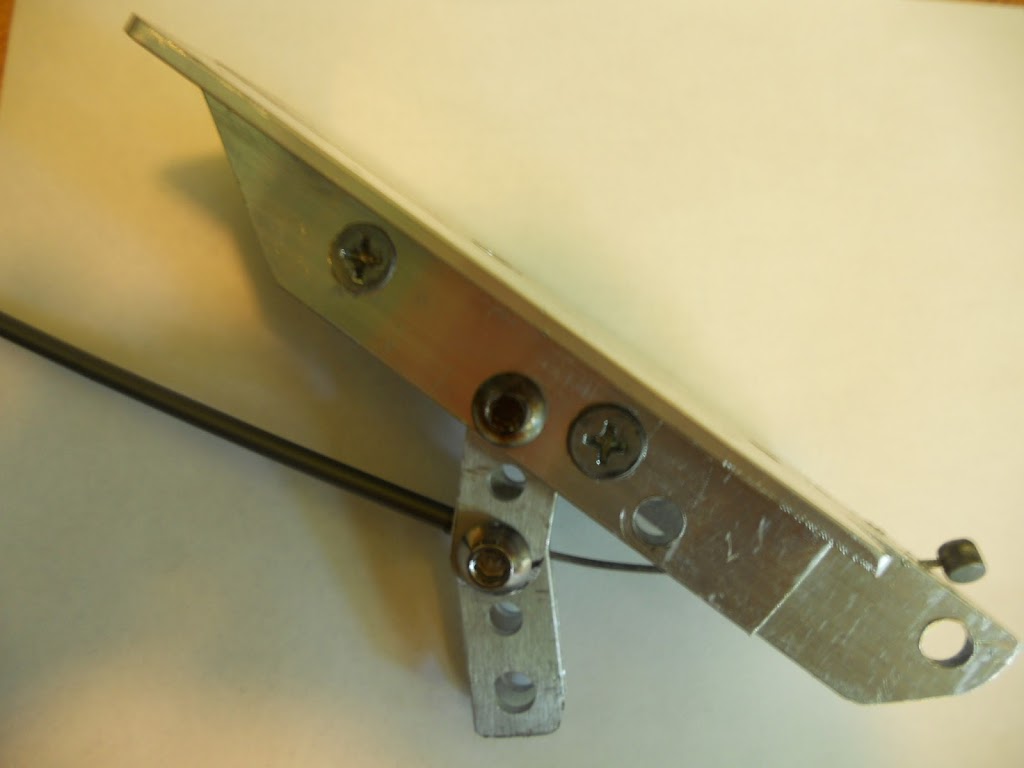
Normally on kick scooters, you brake by pushing down a lever above the back wheel with your foot. The lever rubs against the wheel, slowing the scooter down. I wanted the disk brake to be actuated the same way as normal kick scooter brakes are, so I made a brake pedal out of some U and L aluminum. So that pushing down the pedal would pull the brake cable, I added two pivoting linkages to the pedal. In the picture below, the two fixed pivots are the bottom right and bottom center holes. When the pedal is pushed, the two pivoting linkages that the brake cable housing intersects with are pushed outwards (to the left in the picture).
And here is the whole thing assembled:
Brake lever released:
Brake lever pushed:
Re: Off Road Electric Kick Scooter Build
Neat idea. I like it! :up: Just make sure you don't use it with the throttle opened up. ;)
Re: Off Road Electric Kick Scooter Build
^Let's have a challenge: What'll overheat first?
The motors?
Or the brake pad?
Re: Off Road Electric Kick Scooter Build