ohh yay gear trains :( they can be your best friend or your worst good luck

Printable View
ohh yay gear trains :( they can be your best friend or your worst good luck
Thanks. Out of that pile of gears I've found 22 that will work in sequence, if properly oriented. That should be enough, with leftovers for other places on the case. Got 2 more nights to work then I'll have a couple to work on it. :)Quote:
Originally Posted by DonT-FeaR
Awesome. I am looking forward to seeing how that turns out.
oh ok i shall look forward to it also
Can't wait to see the gear set up you are working on.
Well, I am sorry to say that, due to family, work, and life in general, this project is going to have to be shelved for a while. I will pick it back up where I left off when I have some things caught up and squared away.
Keep up the great work, people.
ok pitty to see it put away but we understand...
get everything all good again and come back when your ready
Ok, so this project had been shelved for a while due to other intrusions. I think those are straightened out for the time being so back to work I go. :)
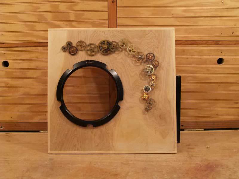
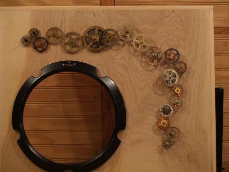
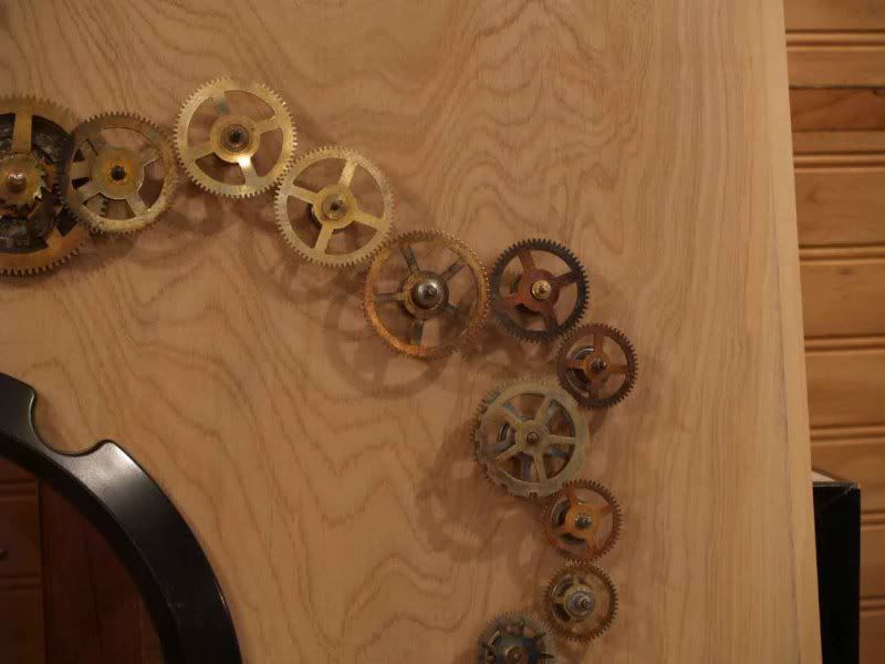
Like most computers, the left side panel on this one is designed to remove for access. As my computer sits on my desk on my right, I decided to put the motorized geartrain on this panel. I am glad to say it's done. :banana: All of the gears are in place and ready to turn. I still have to figure out a way to mount the motor so that it is adjustable for tension, but that's child's play compared to this.
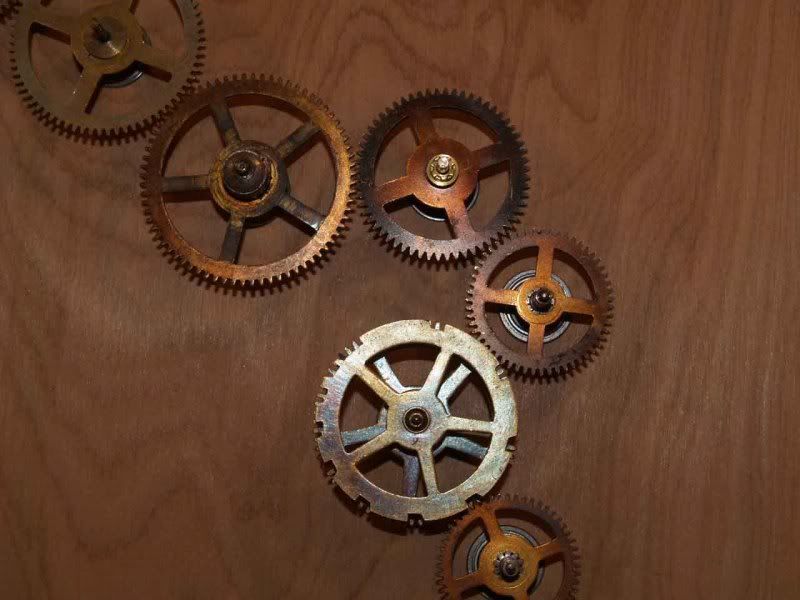
I recall when I had this idea I said "Hmmmm, I know. I'll get a bunch of gears together, sort out some that will turn together and I'll put them in a train on a computer!" Well, that's what I did, but let me tell you, I had no idea. I set myself up for a very complicated puzzle in three dimensions. With pieces from five different puzzle boxes, so to speak. Forgive me if this post is long, but there were a lot of problems to overcome, and I want to share my methods, in case anyone else can use them. These were all pretty much poor man's solutions to problems that any machine shop could have solved in ten minutes.
First off, every gear shaft had to be perfectly perpendicular to the side panel. If it was crooked at all, the gear would wobble and the teeth wouldn't mesh. So far, so good, I have a drill press, problem solved.
That's about the only easy part. The gear shaft also had to turn freely to allow the torque from the motor to pass through the whole train. BUT it couldn't wobble. That was a joy to fix, kicked my brain for a while. Oh! And the shafts on clock gears are not fractional sizes. Or metric. They're wire gauge, or close enough that wire gauge drills do the job. I own a set of those now. :)
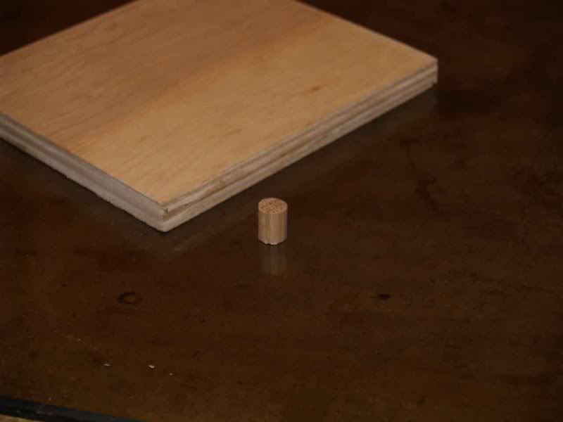
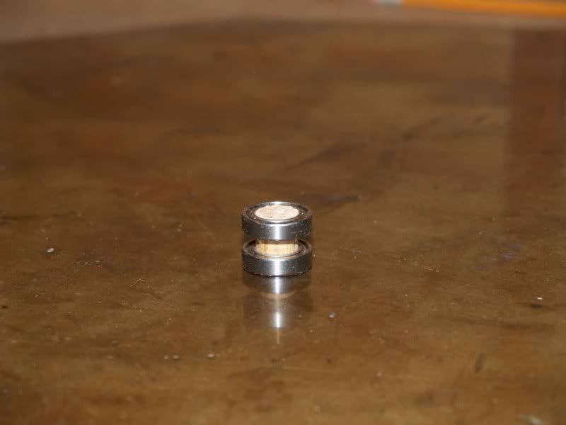
So I couldn't just drill holes in the side panel for the shafts, either the bearing didn't spin freely enough or it wobbled. I thought of nylon bushings, sleeve bearings, ball bearings, name it. I dare you to find ball bearings with the inside diameter measured in wire gauge. :think: In the end I did end up using ball bearings. Thirty-eight of them. I bought bearings that were 3/8" inside diameter and 5/8" outside diameter. Then I cut a 3/8" oak dowel rod down to 1/2" lengths (the panel is 1/2" thick).
These would go inside the bearings to act as a shaft. Then I had to figure out how to drill holes for the gear shafts *exactly* in the center of the dowels. Off even a hair and the gear would wobble, and the teeth would slip on one gear and bind on the gear on the other side.
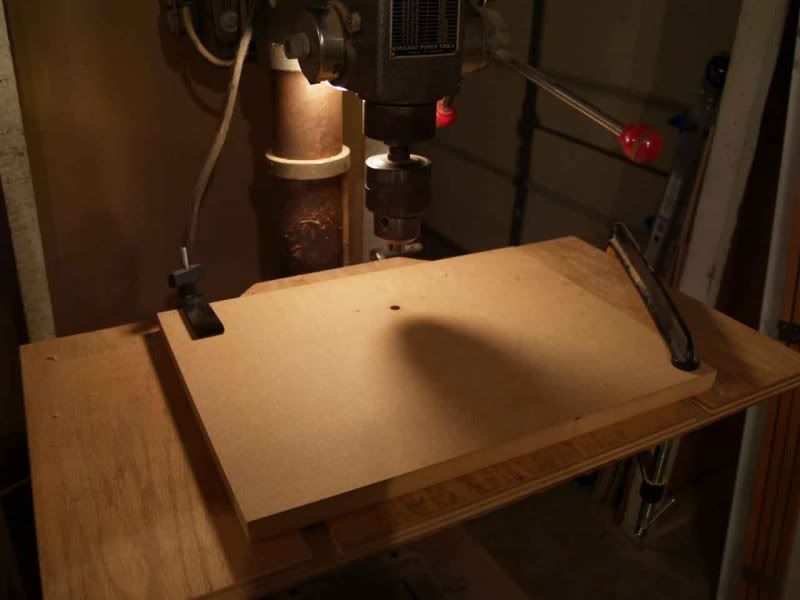
Banged my head for a while on that. I ended up clamping a piece of 3/4" scrap MDF to the table and drilling a 3/8" hole in it with the drill press:
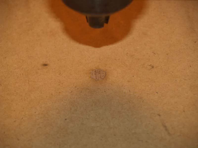
Now, as long as the board or the drill press table don't move, no matter what size drill bit I put in the drill press it is EXACTLY centered on that hole. Used the drill press to press the little shaft into the hole:
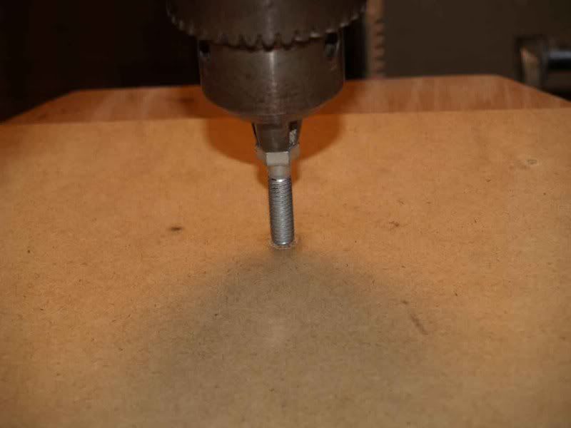
And bingo. Sort out which drill bit to use for each gearshaft (one size small so it's a press fit into it) and drill the hole. Dead center. When it's done I put a bolt on top of it and pressed it out the bottom of the table:
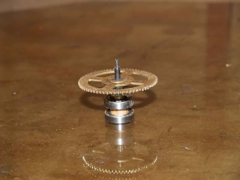
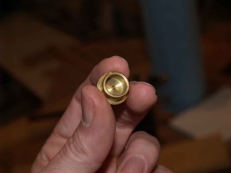
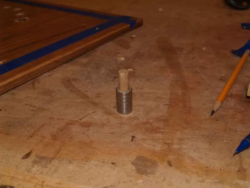
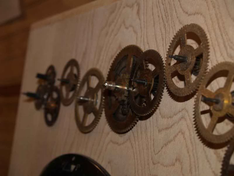
So now the hole is drilled, here's what they look like with two bearings on them, and a gear mounted:
Cool, all the gears are turning freely and will stay perpendicular. The fit is tight enough that the pressure will also control the distance of each gear from the side panel, which *also* had to be perfect. Even a millimeter too close or too far away and they slip. Picky little things. :rolleyes:
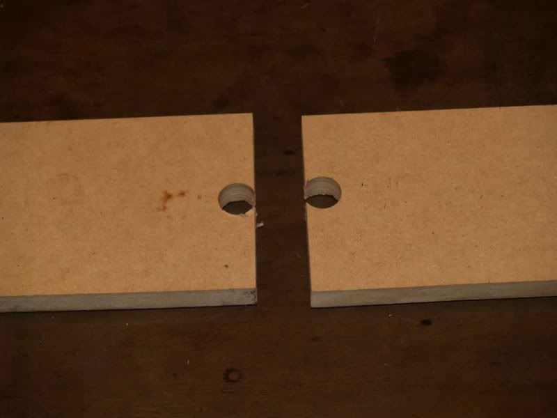
Another puzzle was how to measure how far apart every hole would be from the next. Again, very tight tolerances. I cut two boards and drilled 5/8" holes in the ends of them:
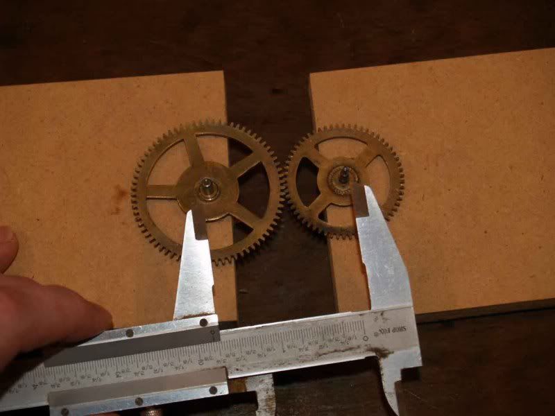
Then put the two gears in question in the holes and got a rough measurement from shaft to shaft with calipers:
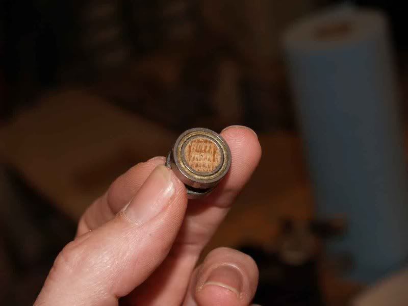
Ok, that's rough, I could only get so precise eyeballing two shafts from the top. I needed a way to drill some holes and adjust that distance closer or further by trial and error until I got it right. This is called a dowel center:
It's a little brass cap that fits over a dowel and it has a spike inside it dead in the center. I slid it over a couple of left-over bare shafts and hit it with a hammer, leaving a small dent in the center of the shaft. Then I mounted two bearings on each of them:
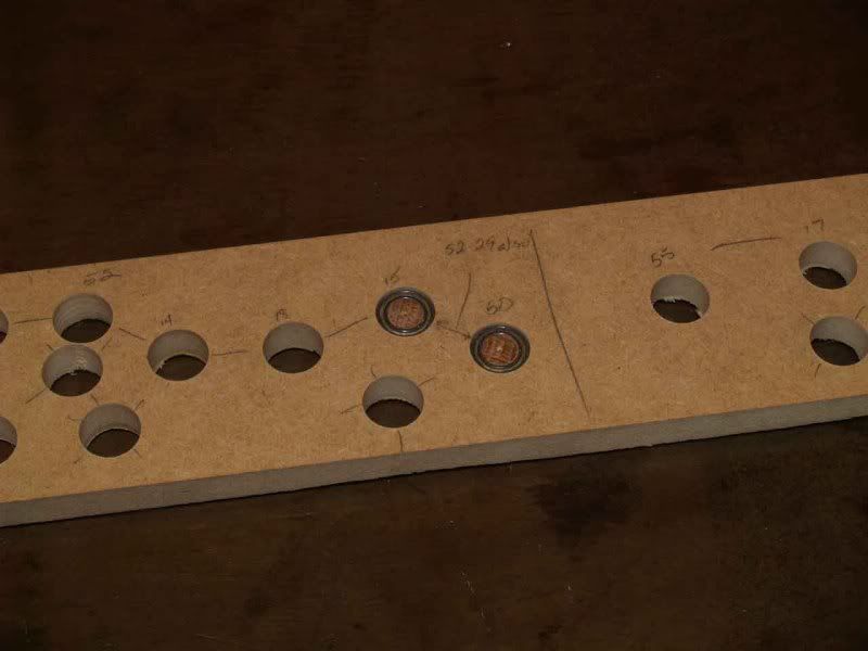
I used these "dummy shafts" as markers for measuring. I drilled another 5/8" hole in another piece of scrap, put the first dummy shaft inside it, then transfered the measurement from the calipers, using the center divot on the dummy shaft to make a mark on the scrap. Drill a hole at that mark and set the two gears in the two holes. Too close or too far away, adjust the measurement and do it again. (Just be sure to cross out the hole you're not going to use!)
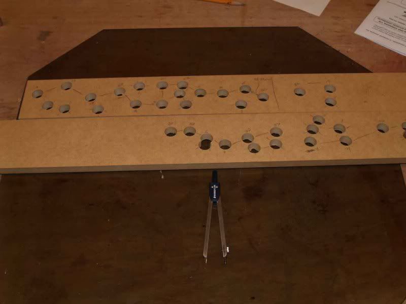
I wound up with two pieces of scrap with a LOT of holes in them:
These are the finished measurements for all 19 gears, each marked one to the other. Now how in the world am I going to transfer these exactly to the panel I'm working with?
I made a pivot by stacking six bearings on a longer piece of dowel:
Drilled the first hole for the primary drive gear (since it could be about anywhere). Put the measurement board on top of it so that the right numbered hole was over that hole and slid the pivot through both of them. This held the measurement board onto the panel but let it turn.
I put that assembly on the drill press and put the bit into the hole beside the one with the pivot in it and drill through the panel. Since the hole in the measurement stick was the same size as the drill bit the measurement transferred perfectly. :D
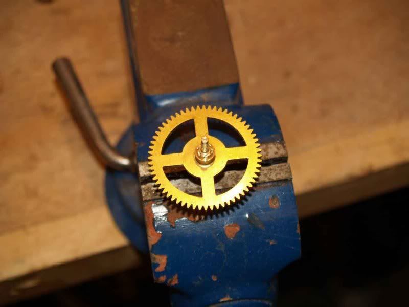
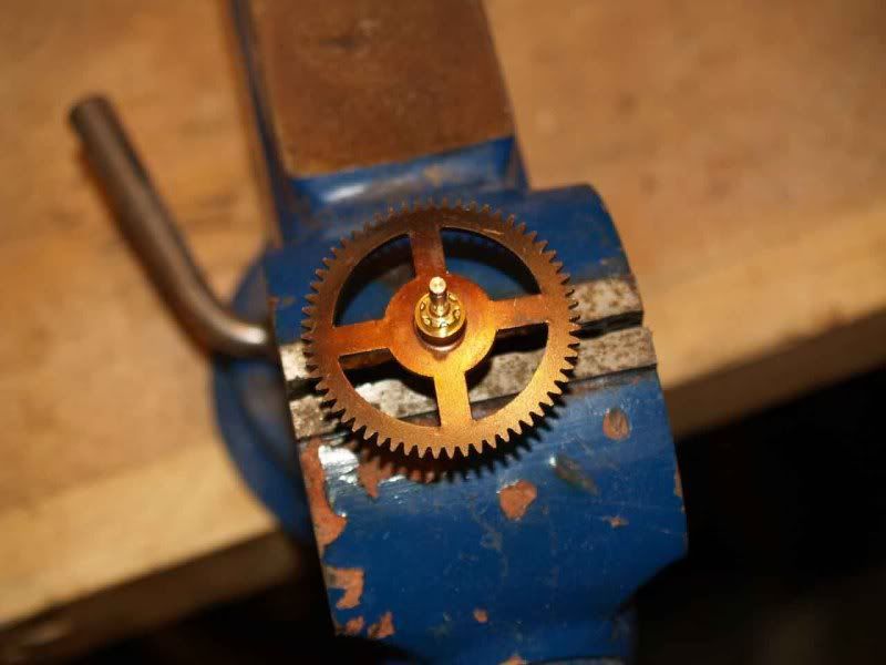
That pretty much got the gears where I needed them, with a few mistakes while learning along the way. I decided to make this build look kind of retro/antique/psuedo-steampunk, so I didn't want my gears to be nice and shiny. It's amazing what brass will do when subjected to a few seconds of a mapp gas torch. :)
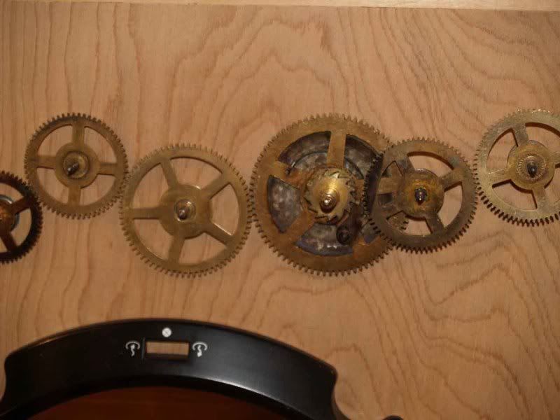
Enough's enough, here's what it came out to:
I have to stain the panel (and the rest of the thing), plan on painting the fan ring you see there and making a custom grill that I think you'll like.
That's where we stand now, and I'll tell you the rest of this build should be a breeze compared to this! (I don't like gears quite as much as I did two months ago...)
wow you have been busy. The gear train looks fantastic. Excellent work.
looks awesome! +rep
Wow! Thats amazing. +rep
OMG! That's epic! Must...have...video!
+rep
Thanks for the rep and the encouragement, fellas!
@ Mach: it's not mobile yet, as I still have to mount the motor, and sadly I have no way of posting video. We're still doing video with tape here. :( Who knows, though? By the time I finish this, holographic video storage may be available at K-Mart.
cool That amazing project
Rep +
interesting project, can't wait to see the final results...
thats great man... very nice
Edit: I just read this whole thread again and realized that I forgot to mention that I had to remake every one of the panels I made previously, which is why this post looks just like the earlier pre-assembly post. The only thing I was able to salvage was the bottom piece. :mad: I also wound up using a different motherboard tray, out of an Apevia X-Discovery case that I dissected.
Just a small update on assembly today. I've decided to assemble this whole project with the brass inserts I used on the drive tower, so that I can completely disassemble it in the future if needed. I got all the panels cut to size, edge banding in place and inserts installed. Check it out:
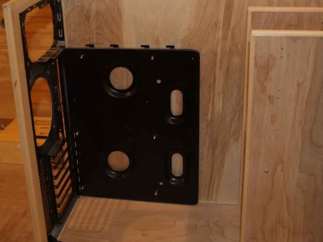
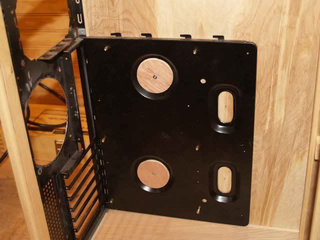
Got the hole cut in the real panel for the motherboard tray, turned out perfectly. :) This particular tray is designed to be removable, and after I installed it the only thing holding it in place are three screws that go through the rear panel, which will have to be removed before this thing is done. The rear panel itself is not a problem but I had to figure out a way to secure the motherboard tray.
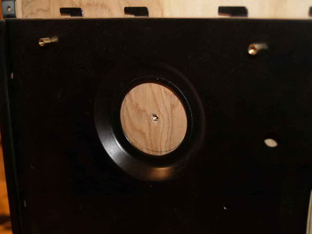
I had to have a way to secure it that wouldn't leave anything sticking out higher than the surface of the tray (like screw heads), as with my luck I would put it in just the right place to short across two pins on the back of my board and fry every component I have. I decided to use the depressions in the middle. I put a brass insert in the center of the two circular ones.
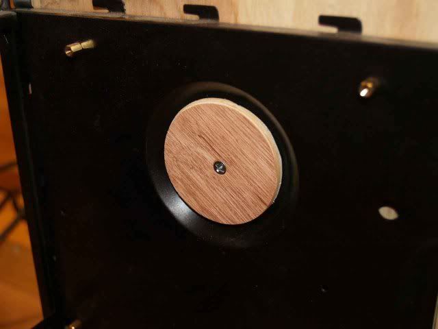
Then cut two circles of Luan slightly larger than the bottom of the depression, countersunk the screwhead and screwed them in.
When it's done, of course, these will be hidden under the board, but they will still get the same paint treatment the tray is going to get.
That's it for now, I'm about to go back out the shop and start laying out the front panel, have to cut for both DVD drives, the front temp gauge, the on/off switch and the intake fan. I've got other holes to cut in it but they will have to wait until components arrive for layout reasons. That's one reason I love being able to take it apart and put it back together as often as I need to.
Wish me luck, it's cold out and my shop heater went out last night! :mad:
Looking good man. Bad luck about your heater.
really cool idea
Frame looks rock solid, can't wait for more progress shots.
great idea man... case is looking sweet
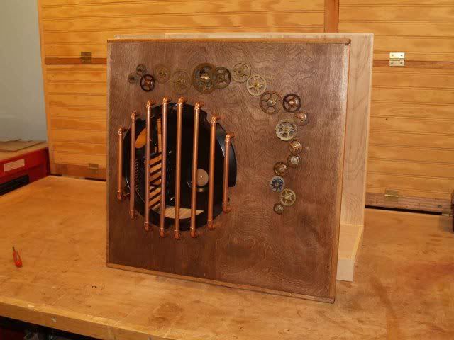
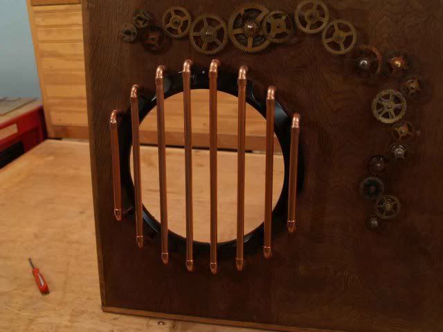
I got the left panel stained and the fan grill completed. :D Although I love the way it turned out, I will probably experiment with the copper pipe and heat and see if I can get a better color. My original design for the fan grill was a lot more complex, but turned out to be cost prohibitive. Sorry, but I am not going to be the proud owner of a $150 fan grill. All in all, I'm glad, I like this simple design better anyway.
Tell me what you think of it.
That is freakin awesome!!!!!! +rep for the unique design.
Sweet man. The copper pipe looks great on there. +rep
Bioshock theme :up:
Love that side panel
good work!
that is like the coolest side pannel ever... wow... nice work
LOVE the grill made from copper pipe, looks great. Nice choice of stain also.
the grill looks nice :up: flows with the look of the geartrain :D
I really dig the gears train.Where can I get my hands on them ? :)
Great work, just read the worklog and subscribed.
The fresh copper kinda looks out of place, maybe torching the grill too?
The gears look great!
Any more progress on this bad boy?
Apologies on the delay, but I've been rethinking the project and have been in a redesign phase. I've decided to hang the hard drives externally on the right side of the case and utiliize my motherboard's two eSATA ports. I'm planning to install them in aluminum hard drive silencer/cooler enclosures and mount them outside on the right side panel, probably wrap copper tubing around them.
This frees up a lot of room inside and I don't think I need the wooden drive tower any more. I'm planning to make a new one out of copper pipe since it will only be holding the two optical drives. Although this means remaking the front panel, since the drive spacing will be different, it frees up a lot of room inside for cool stuff. :D
I've also been frowning over the whole geartrain and have some ideas that could make it a lot better.
Sooooo... any more progress, yes. You just can't see it yet. The next pics should be of the new geartrain, working on parts on that, plus I have to learn how to paint like Slamaa. :)
I like the e-SATA idea, good thinking.
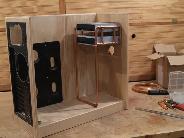
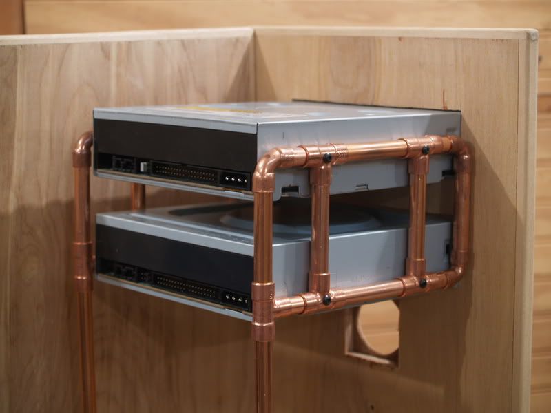
Since I decided to mount my hard drives externally, it opened up a lot of room inside the case, and I decided that I don't need the large wooden drive tower any more, just for the two optical drives. So, to free up even more room for cool stuff to look at (and to keep this thread alive), I built a new cage out of copper pipe.
Once it's soldered together it will be held in place with a bolt through the front panel on each side and two through the bottom also. I plan to run all of the wires inside the case, data and power, through copper pipe also, so no wires should be visible at all when I'm done. The drives, fans, PSU and motherboard tray will be getting a corroded look, probably a bronze/black combination. I bought an airbrush today and will be experimenting with paint colors. Still waiting on the last parts for the new geartrain, hope to have pics of that next, but I'll want to have the paint process down before I post those.
Not sure what I'm gonna do about this copper, it's way too shiny for the overall look of the case. I'll experiment with heat and maybe some of that patina solution and see what I can do.
That's it for now. It's not dead, just slow. :D
Shame your not using the original wooden drive bays, they looked very good. With that said I must say I love the copper pipe drive rack, goes very well with the mod.
Is it me or did you make it a little too tall? It looks as if the drives have to slant down a little to fit in their slots.
No, you're right, the two long uprights are just a hair too long, I've got to trim them a bit before soldering. Good eye!
As the for wooden drive bay, thanks and I agree on the appearance, but when I'm done it will look *much* better. ;) I'm going to have to buy a couple more motors.
Great work! I really like this project.
For the shiny copper, you could try liver of sulphur. It will deepen the brown of the copper and give it more visual depth. http://metalloarts.com/hammered-copper-counters/
"Liver of sulphur", eh? Interesting already, I'll have to research that, thanks very much and +rep. :D