well this is on the way to use with a pot for a variable voltage output :D

Printable View
well this is on the way to use with a pot for a variable voltage output :D
Aww, party pooper. :( Sticking extra boards in there..grumblegrumblegrumble.
Nah, that should work fine. Looking forward to seeing it in action.
well I'm still using my LCD for the straight monitoring, that secondary LCD will be for a separate 12v line that I will be able to regulate down to 3v or so
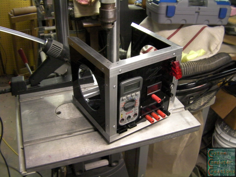
Alright so I got some more work done on this thing!
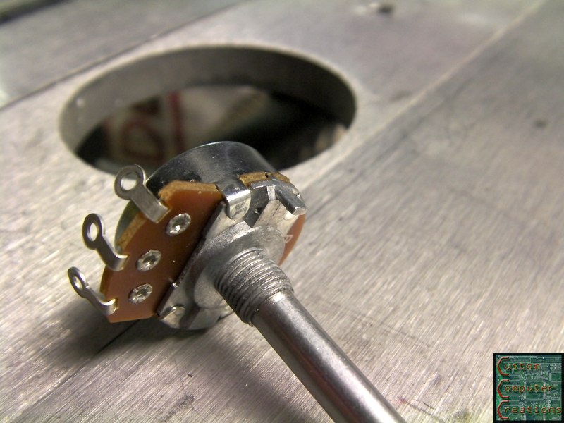
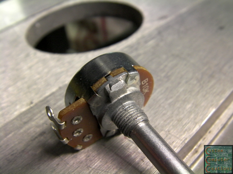
The pot I got for the variable output had 2 problems. First there was this little tab in the way, but that was easily taken care of :D
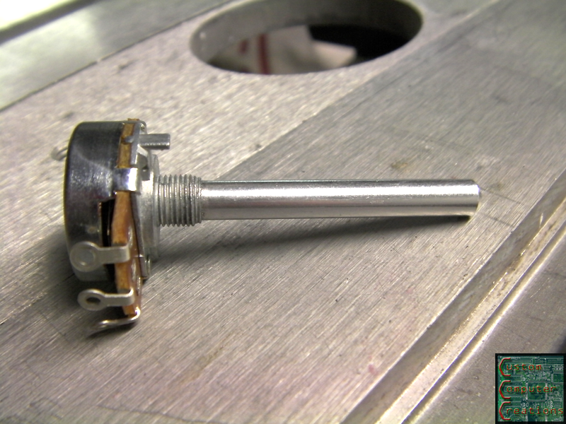
Second, it was WAAAYYY too long, but that was easily taken care of as well :D
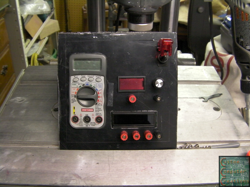
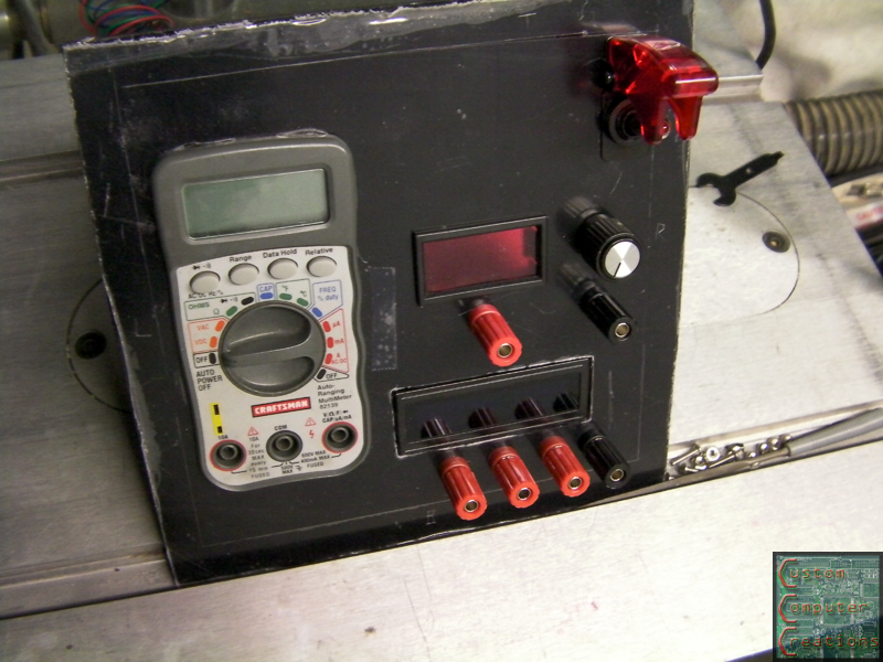
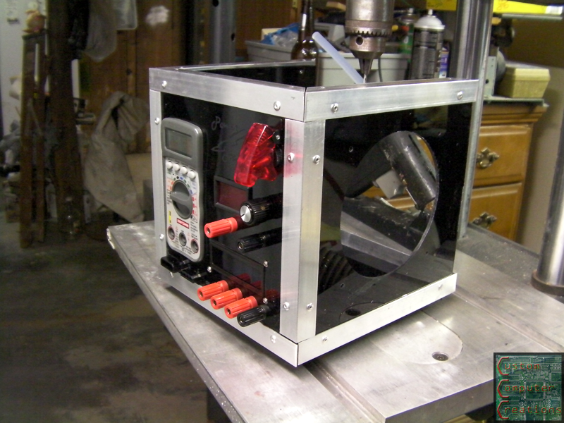
I also got the front panel mostly cutout and parts temporarily installed. All that's left is to cut the openings for the molex's and the little opening for the LED tester :D
That's it for now!
Interesting project SXR. I'm looking at doing something similar but measuring voltage, power, and current. I'm looking at TI's INA219 right now as an option. Still kicking tires and learning. I've got a few ina169's if you want to add current measurement.
How hard was it to dismantle your PSU? Anything to watch out for?
Thanks for the offer, but the SMT package won't work for me for this, I need a through-hole package.
As far as dismantling the PSU goes, it was pretty straightforward. A few screws for the housing and such. The only hard part is the power connector and switch. You either need to cut the housing (like I did) or de-solder all the wires from each one and get them out that way. I figured I didn't need the housing so I just cut it, it made things easier.
Watch out for the caps, make sure not to short them with anything (like a wedding ring) during disassembly :D
Thanks, I'll keep that wedding ring thing in mind :)
Great work so far! I have almost the exact project going on right now. I'm going to have 24v, 12v, 5v, 3.3v, and a variable line. I was also thinking of adding some usb ports for charging/testing usb powered things and a fuse tester. I like the suggestion of an led tester as well so I might have to borrow that idea.
I like the idea of the USB port for testing/charging...I may have to borrow that :D
Update time!
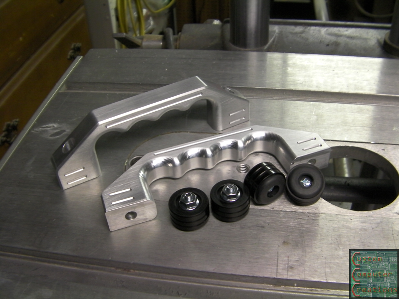
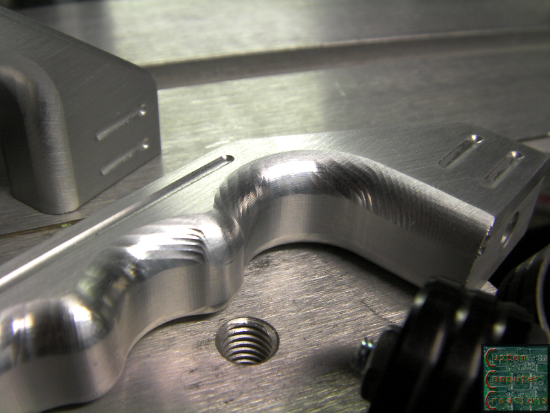
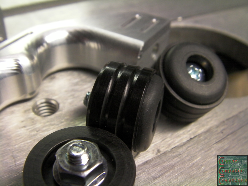
I got these SICK case handles and feet in from MNPCtech!
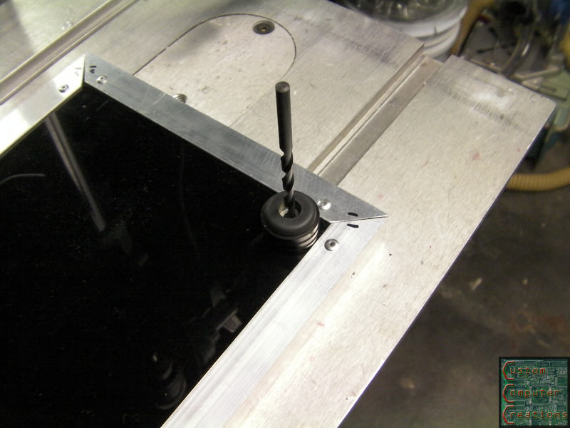
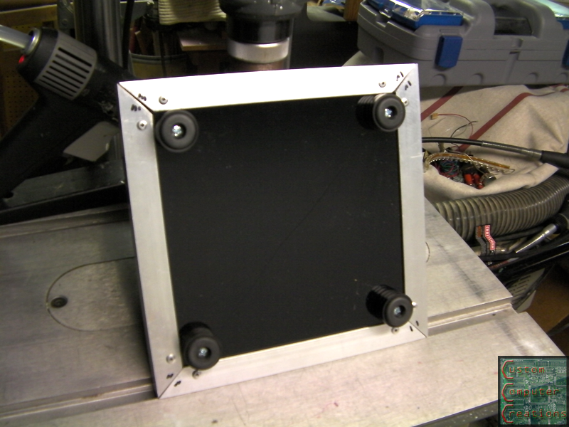
I placed each foot in it's position and marked it with a drill bit, then drilled the holes and mounted the feet.
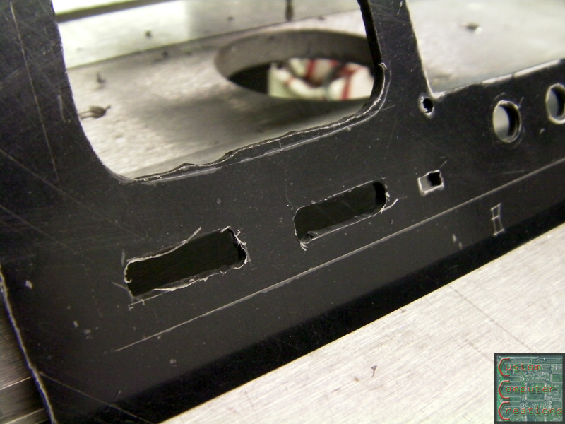
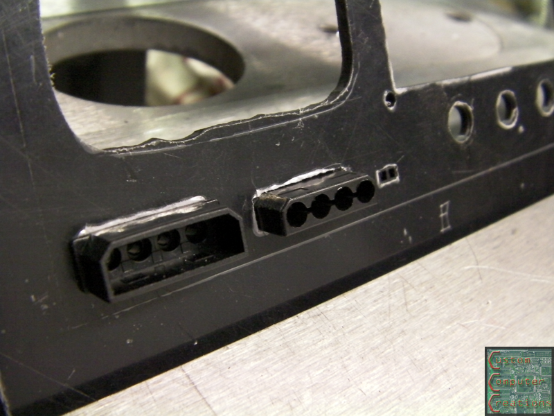
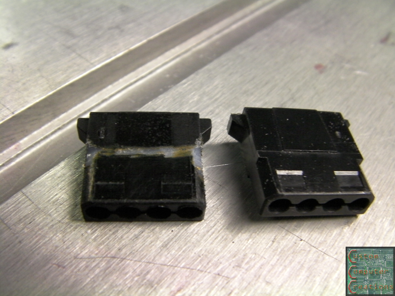
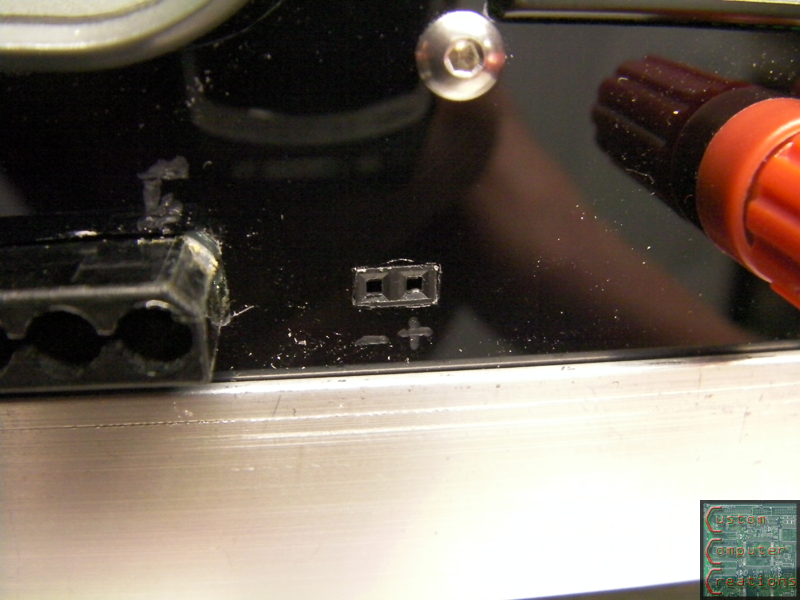
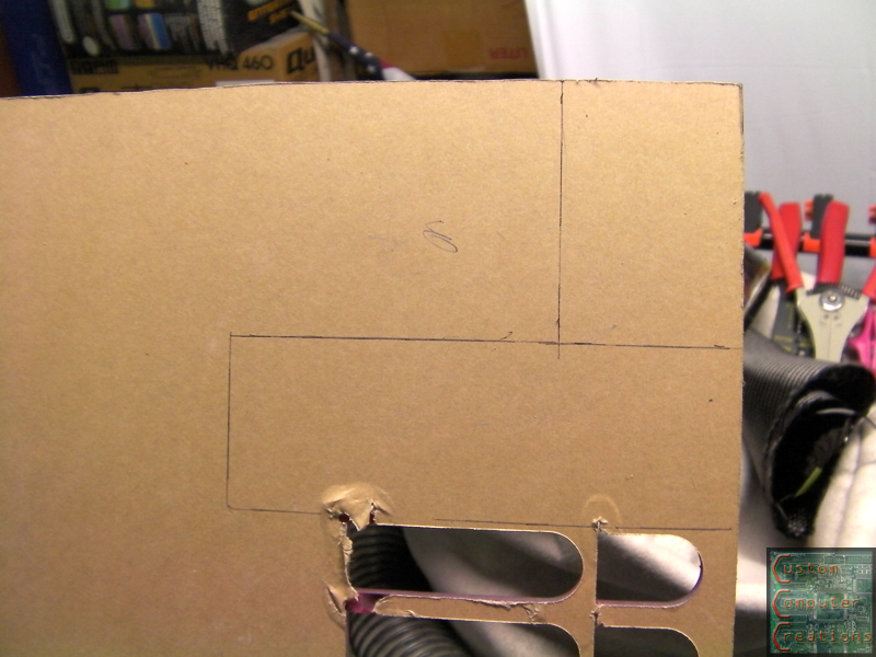
Next I got the rough cutouts for a male and female molex as well as a 2-pin MBB header (for the LED tester) done, then spent some time filing until the pieces fit.
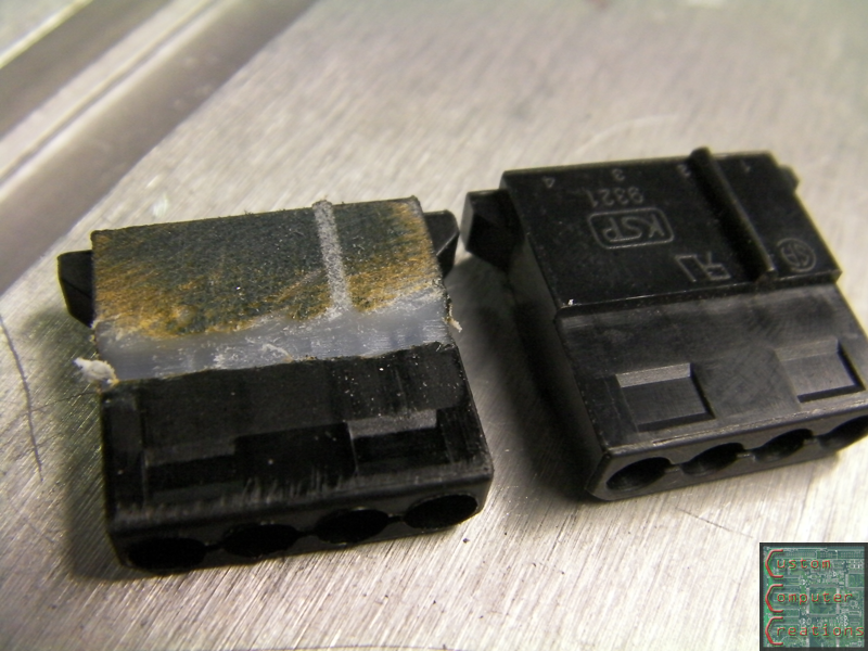
Now I had to modify the male molex so it would go through the panel enough for the pins to properly connect. I also found out, interestingly enough, that they're not made of black plastic!
Now I've got to decide where I'm going to put a USB connector (or two :D), and I've been throwing some design ideas around in photoshop that I'll etch into a blank space on the front. Granted it won't have the ability to be edge-lit, but it should still look sweet :D
Uhm...
Where are you going to get 24V from, Crimson?
AFAIK, the max is 12v in a standard PSU
Even Apples only have 16?/20?V on theirs.
Good progress, tho, SXR
Thanks! you can use some transformers and such to get 24v if you really want to :D
http://www.aaroncake.net/circuits/12...er_Circuit.asp
:EDIT:
actually I may use that circuit and have a 24v supply line for the adjustable one, rather than just a 12v :think:
Update time!
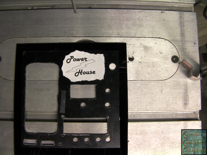
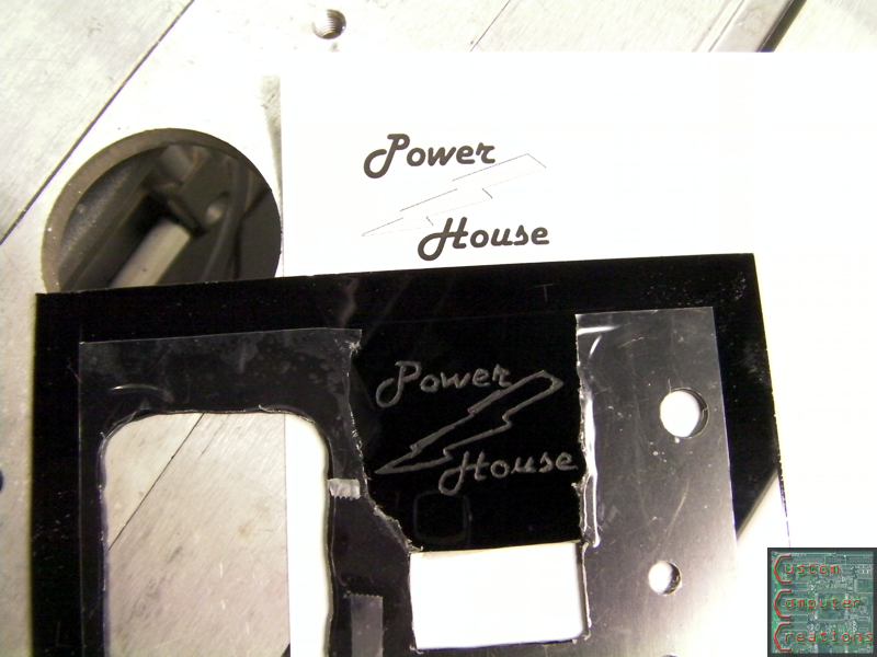
I made this logo in Photoshop:
Then I printed it out and taped it to the front panel:
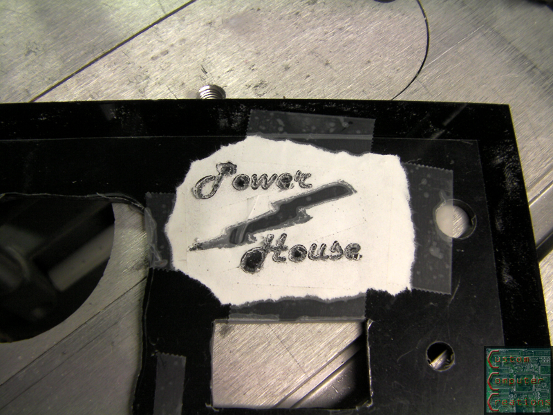
After a quick run-over with the engraving bit:
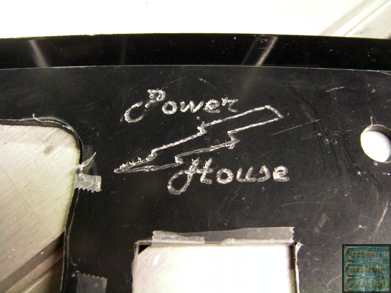
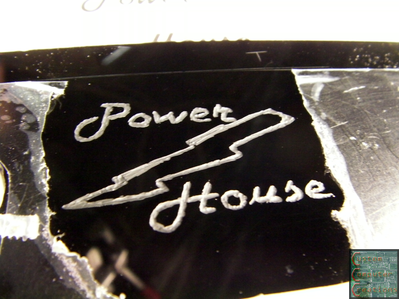
Then I removed the protective film and finished it up:
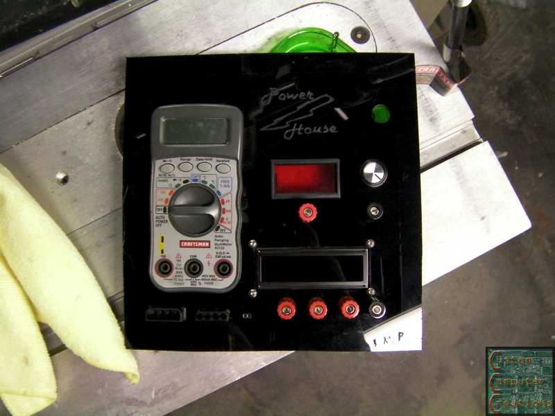
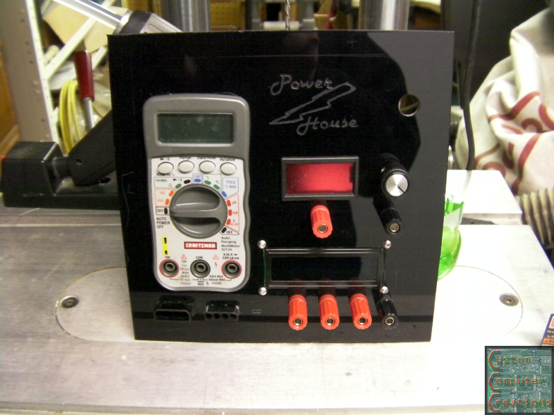
Then I got everything mounted to the front panel, held in with a dab of hot glue here and there:
Then it was time to start final assembly!
I marked the positive and negative for the LED tester with the engraving bit as well:
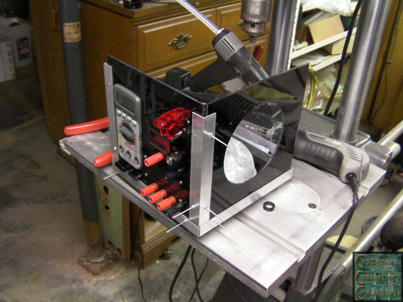
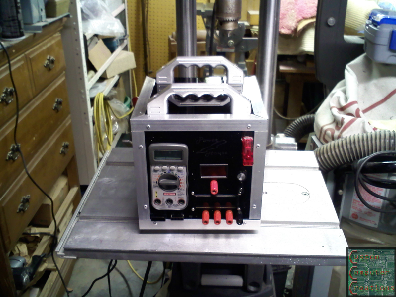
Then I went about mounting those sexy MNPCtech handles. My camera battery was dead so I couldn't take pics of the progress, but it was just more temporary assembly and marking and drilling holes. I shot a final pic with my cell phone though.
The top panel is not yet mounted, as I need to install the PSU and other internals and do some soldering before I permanently mount it. I'm also going to cut some kind of a door in the top as well, so that I can get in and change the fuses in the multimeter if needed.
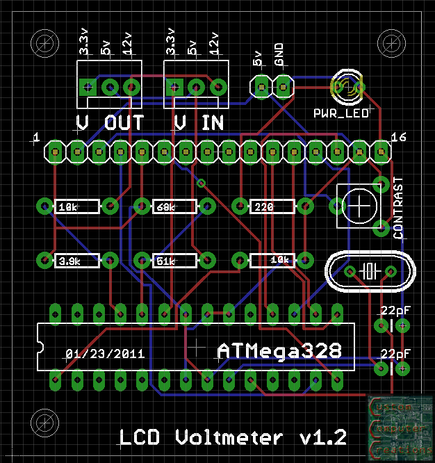
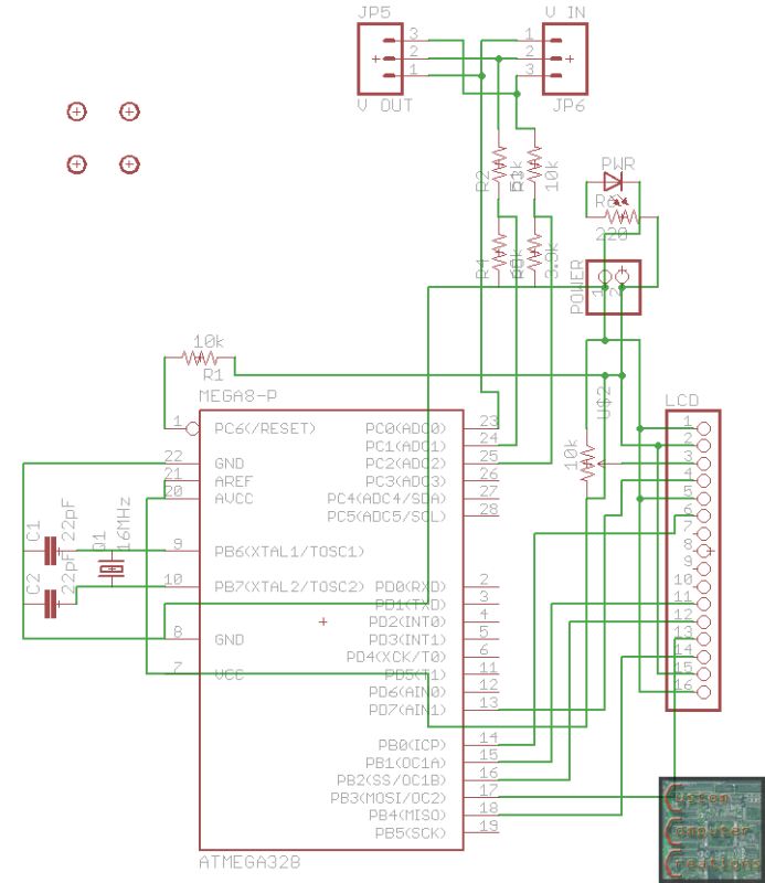
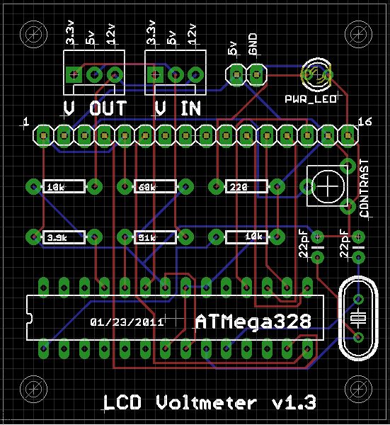
I also made some changes and revisions to the schematic and board designs:
That's all for now!
Ah man you got me thinking now how useful something like this would be...... And I'd have me a bit of a head-start too as I have had a shuttle case lying around for a couple years now just waiting to be made into "something".....
that case would be nice for it! It would be a lot roomier than the one I'm making. Now that I'm trying to stuff things into it I'm wishing I'd made it 10" x10" or even 12" x 12", rather than the 8" x 8" it is now. Ah well, it'll all fit, I just need to get creative :D
Time for an update! :D
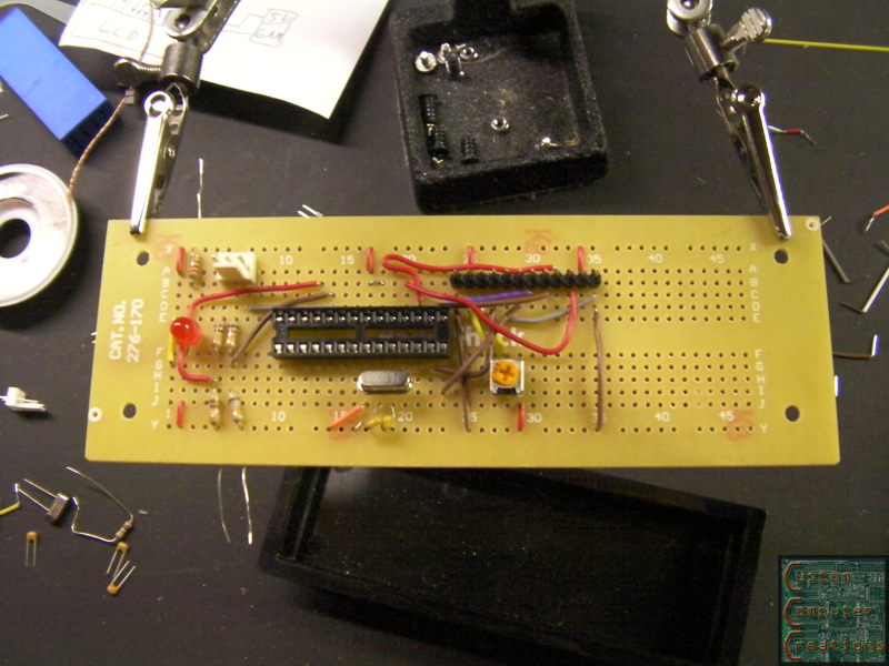
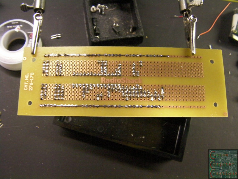
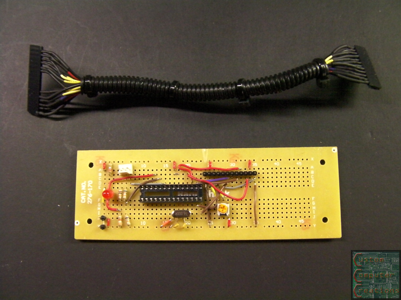
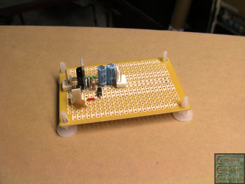
I got the parts laid out on a board.
And got everything soldered up.
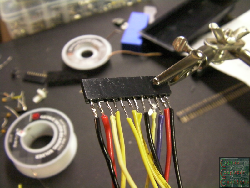
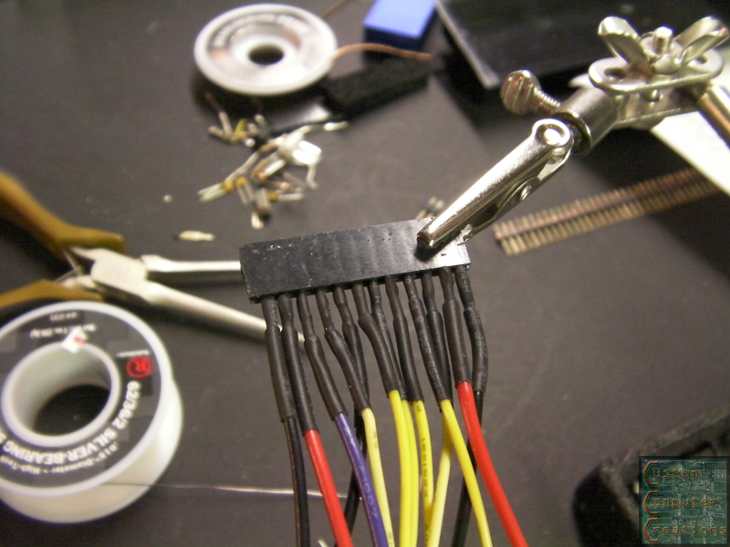
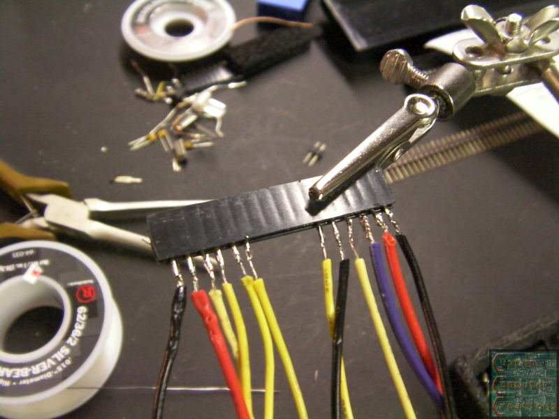
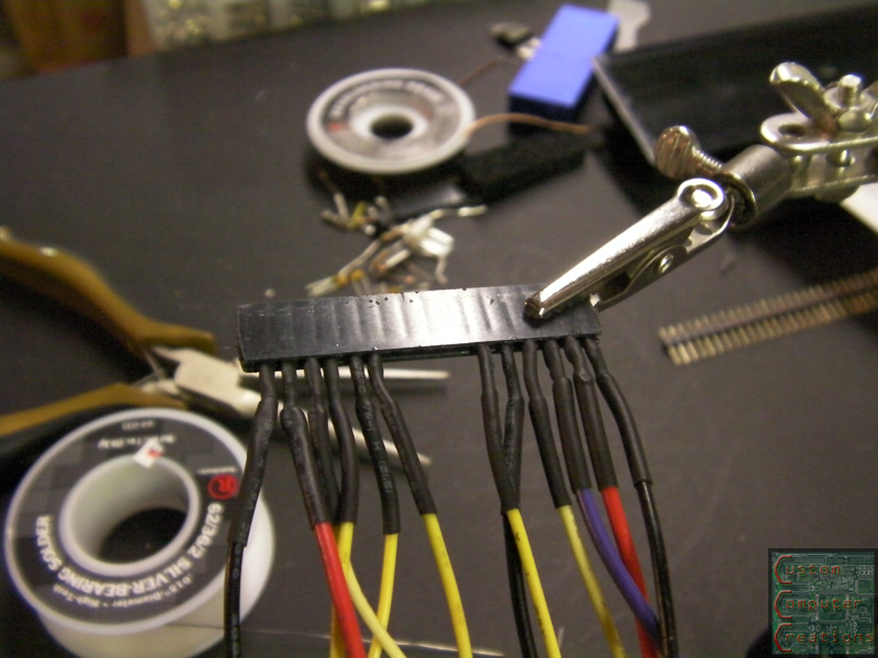
Then I made a harness to connect the LCD and the board.
And ready to get installed!
Now pretty much all that's left is to wire up all the internals and finish the top and rear panels! :D
new version of the board. I noticed some errors with the last version, so I corrected them, and rearranged some parts :D
ok so I think I found a simple easy way to get 24v on the variable output. Radio Shack has a 120VAC to 25.2VDC transformer for $7. Problem is it only outputs 450mA. They have a 120VAC to 25.2VDC 2A version that's bigger (read: won't fit into this enclosure). The question is - is 450mA going to be enough for most small electronics? I was thinking I'd need at least 1A. :think:
It'll be a lot more efficient if you just make or buy a DC-DC converter circuit. No sense in converting from AC to DC more times than you have to. It'll also let you put a bigger load on the bigger rail and let you easily upgrade it later if you want to replace the PSU.
I think I'm going to scrap the idea, and just use the link that CJ posted (once I can get it to work right) to hook a variable to a 12v line. This way I can go from 1.25v to ~10.5v or so, in addition to the dedicated 12v, 5v and 3v lines
We had to do a project like this in high school. We then used the power supplies we built on our next project which was to design and build light bulbs. We modified our design and built it to use a potentiometer which gave us greater control. It was pretty awesome.
I've heard that you can take the -12 line from the 24pin connector and pair that with a +12 line and you'll get 24v. I did it with my current bench supply project and it worked, not sure if there's any risk to doing it but I've read it in a few places that did ATX to bench supply mods.
this, my friend, is a wonderful idea which I will have to research more. +rep to you! :D
ok so that idea is out the window. You can do it, but you're limited to the amperage the -12v can supply, which according to this review is only 0.3A, which is way too little. I'd be better off with the 480mA 120AC to 24DC converter :facepalm:
I think I'll just hook it to the 12v for now (which after the adjustable reg will give me ~10.5V), and whenever I figure out an easy 24v solution I'll work it in. Thanks for the idea though! If I had a better PSU with 0.8A or even 1A on the -12v it'd be fine.
Ahh, I think I'll go check mine now!
Update time!
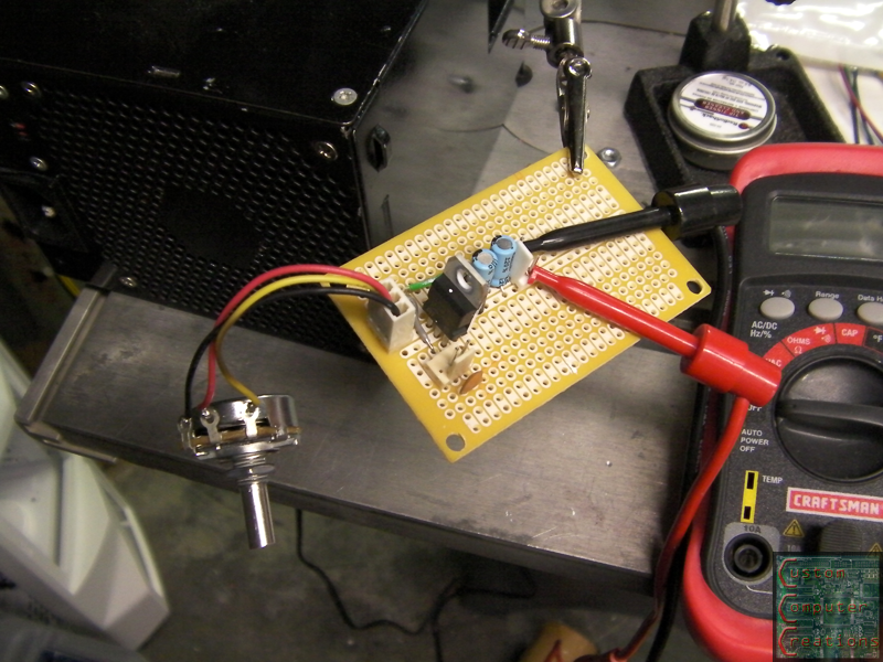
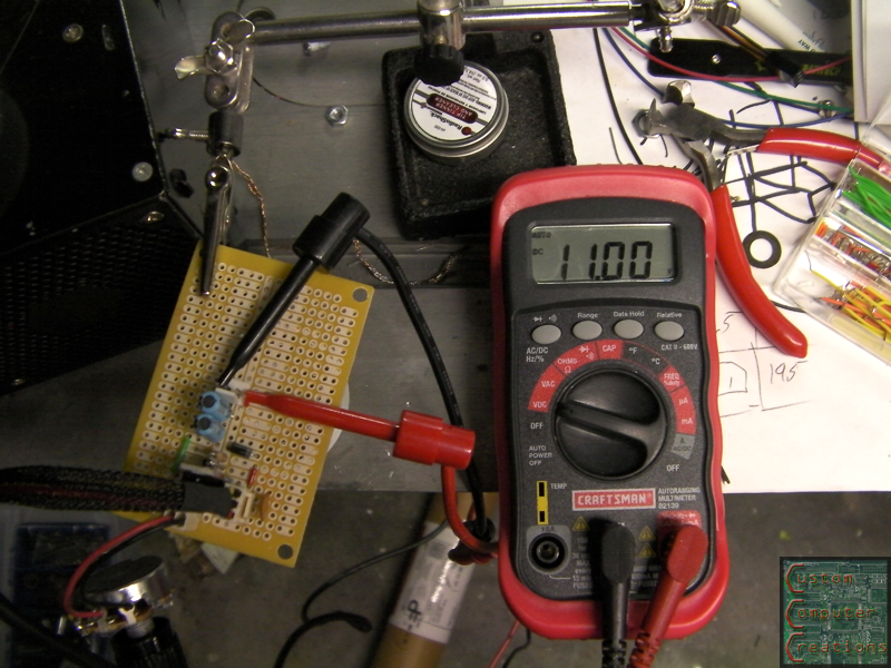
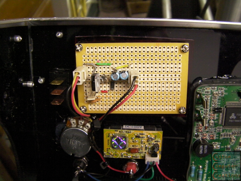
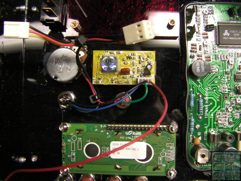
So thanks to CJ, I made up this nice adjustable voltage regulator unit.
I used a 10k pot instead of a 5k because I had it around. With a 12v input, all the way up gets ~11v, all the way down is ~1.25v, and I can go anywhere in between :D
Now I had these nice little PCB clips I was going to use to mount this board and the board for the LCD. Only problem is, whatever kind of plastic these are made of is not compatible with CA glue. I glued one to a scrap piece of the black acrylic as a test, and I hardly touched it 2 days later and it popped right off.
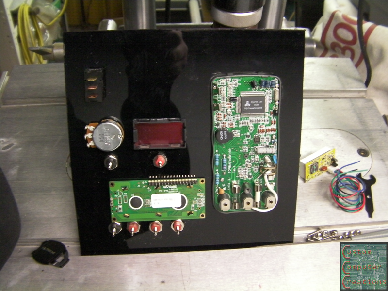
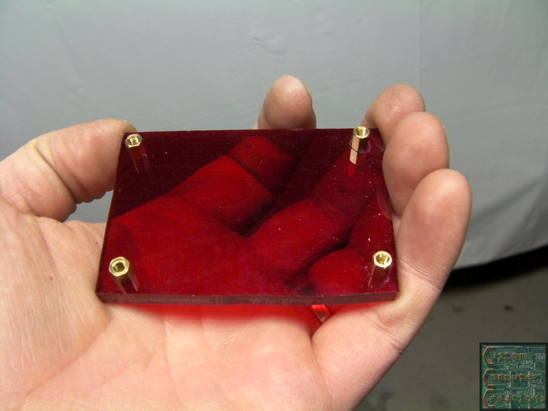
So instead I cut some scraps of red Acrylic I had laying around, then drilled holes and threaded in brass standoffs to mount the PCBs to. The red parts I glued to the inside of the case.
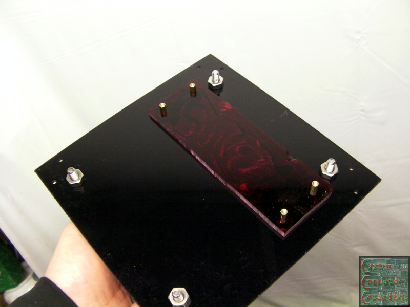
The one for the LCD I decided to mount to the top panel because that was really the only place I had room to put it!
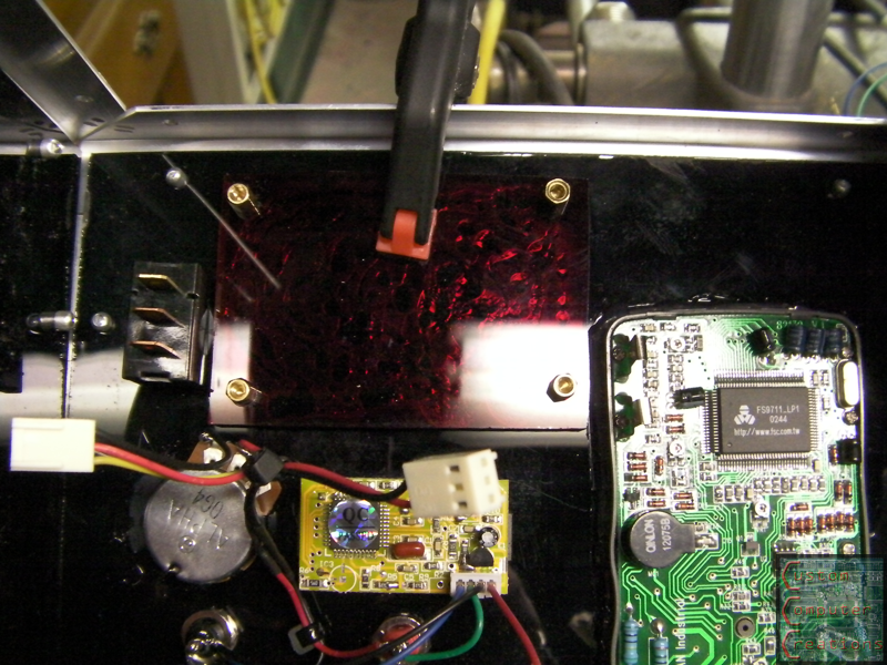
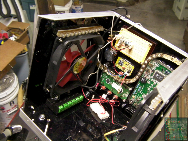
Here is the VR board mounted and the pot and output and ground connectors hooked up.
And a shot of the wiring done for the LCD readout that's hooked to the adjustable board.
I also started cutting wires on the PSU and adding connectors for all the various connections. I'll get pics of that next time I do some work on it :D
Looks good. IIRC, if you use a lower resistance pot you can get closer to the input voltage..not 100% sure about that though..
nah I tried with a smaller thumbwheel 5k one, and it only got to 10.5, and when I hooked up this 10k one it got to 11, but that's fine :D
Hopefully down the road I can find a way (in a small size) to get ~24v to put on that adjustable output. There's that RS 120AC-25DC @ 480mA one I linked to for $7, but I don't think 480mA will be enough. The next one up is a 3 amp one, but it's physically too big for me to fit it in there lol
check out "charge pumps". here's a description from wikipedia so i don't have to type a whole bunch. http://en.wikipedia.org/wiki/Charge_pump
i really don't know too much about how much current they can handle, but this may be a way for you to get your 24v.
i just recently learned about them at work. we have a small product that uses a charge pump and it baffled me how there could be a 6v amplifier power circuit with only a 3v input.
anyway, just a thought for you.
thanks! +rep
so, i talke dto one of the engineers here and this is the chip we use. it's a lineartech LTC3862.
there are a lot more components that go into the circuit, but the engineer says it will take a 12v input and produce a 24v output with plenty of current for you.
you'll just have to look at the datasheet for example circuits probably.
cheers.
Found it, thanks! AND they've got a request samples button...I'm going to get one or two. HUGE thanks!!
http://www.linear.com/product/LTC3862
actually...one little problem...of course...their chips are all 0.15" SMD's!!! :facepalm: that's useless for me lol
hell I should just get this! up to 55V/3A output!
http://cgi.ebay.com/12V-24V-Step-up-...item2a0dcb7b16
there you go. all done and ready for you. for ten bones i'd forget about all teh research and fabing you'd have to do and just buy that.
yea I'm going to scoop up one of those, that makes things VERY simple :D
Thanks again for that info though, it was much appreciated :up:
Update time!
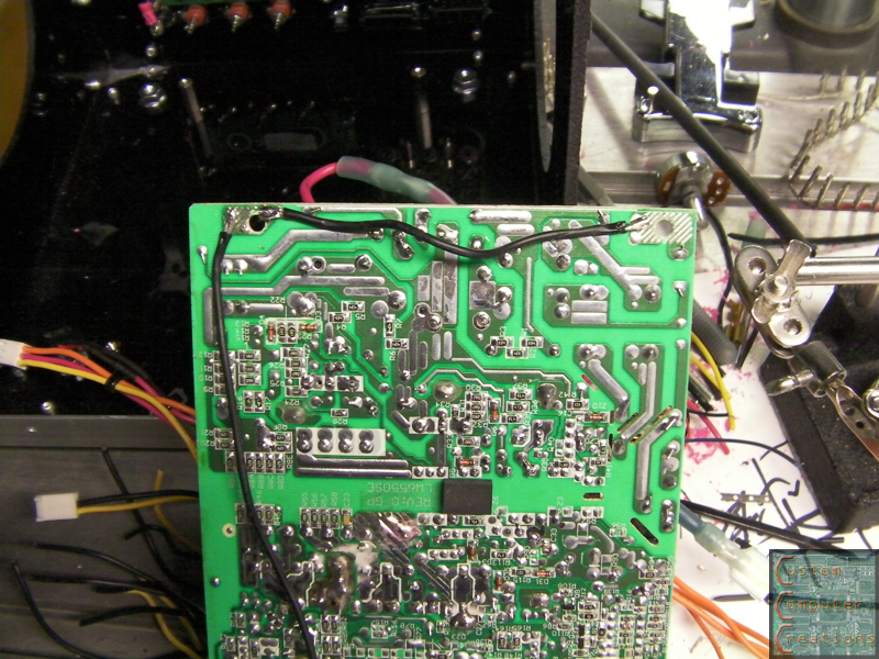
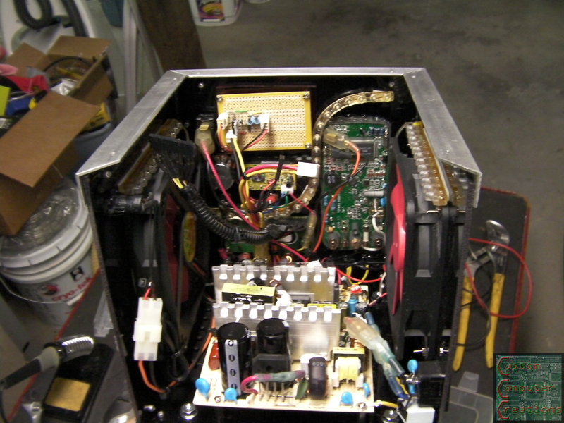
I started off the night by soldering wire to the PCB of the PSU to connect the corner grounds. These would normally be connected by the steel case that it's mounted to, but in this case it's mounted to plastic, so this had to be done.
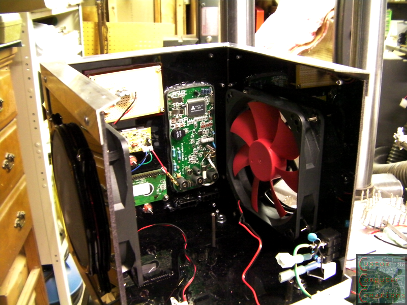
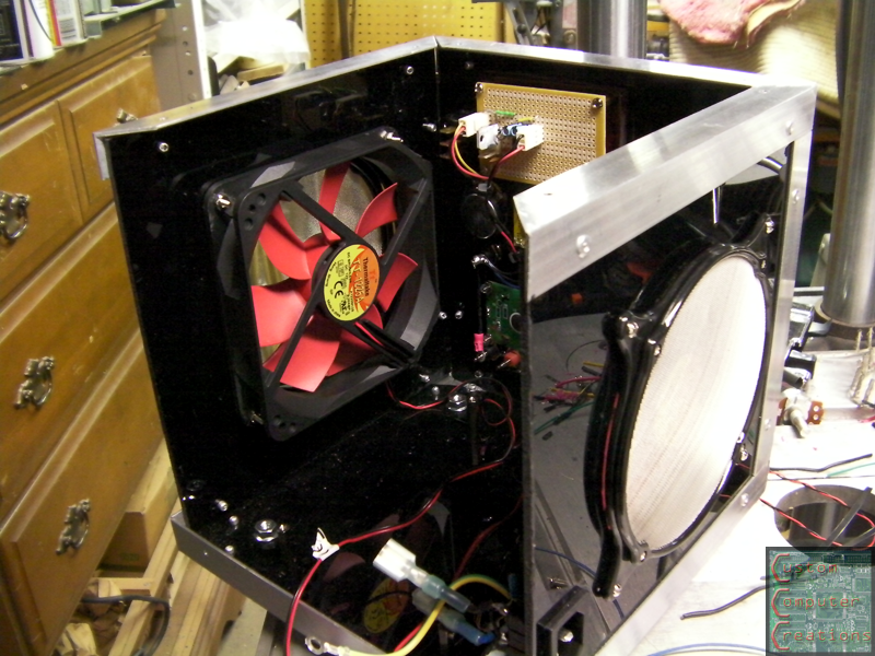
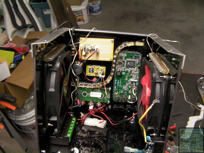
Next up I installed the fans, one intake and one exhaust, and the mesh covers over the outside.
Next up I worked on the interior lighting. I had to do something to snazz it up a bit :D I used one long white LED strip and 2 shorter amber ones. I stuck these inside with double-sided tape. The control box is under the LH fan, with the green terminal blocks.
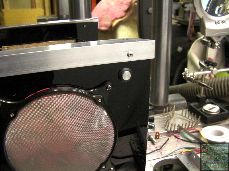
I then drilled a hole and installed the power button for the lights (in case they get annoying for whatever reason)
And a short vid of the lighting. The amber LEDs stay on while the white ones blink slowly.
And then I installed the PSU and hooked up all the wiring.
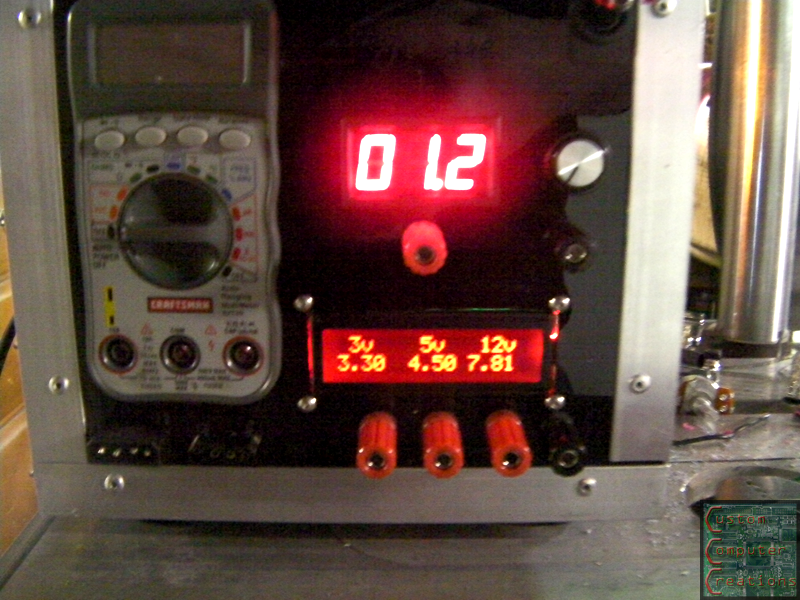
And it works!
And a (crappy - need to redo it with better lighting) vid!
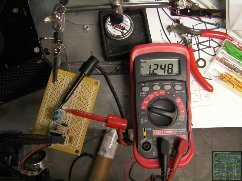
As you can see I need to tweak the coding, as the 5v and 12v reading are a tad off. I checked them with the meter to be sure, and the output is correct, but the LCD reading is incorrect.
I'm also having a few issues with the multimeter, as it's being powered by 3v from the PSU, and grounded to the PSU. First off, because it's grounded through the PSU, it shares internal grounds with all the ground binding posts, so only the positive test lead is needed. Second, this meter's readings are low for some reason, by about 1.5v or so. I wonder if it's backfeeding through the PCB :? Maybe I need to put diodes in the supply line to the meter?
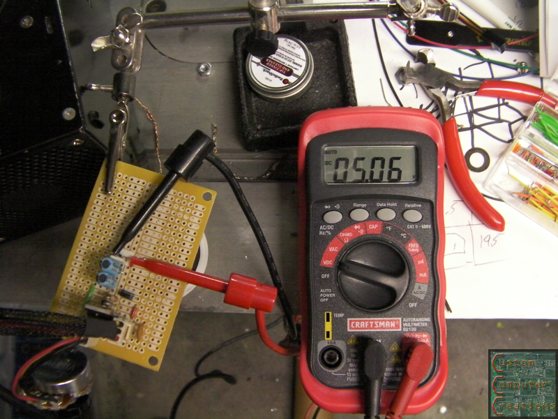
I tested it with a separate meter, and all the readings are correct. I may just take the 3v and gnd off the meter and use batteries with it again to keep it isolated. I'll try it and see how it works out.
That's it for now!
ok so I just ordered this 12v to 24v booster, so in 3-4 weeks it'll be here, which means I've got plenty of time to sort out the coding for the LCD :D
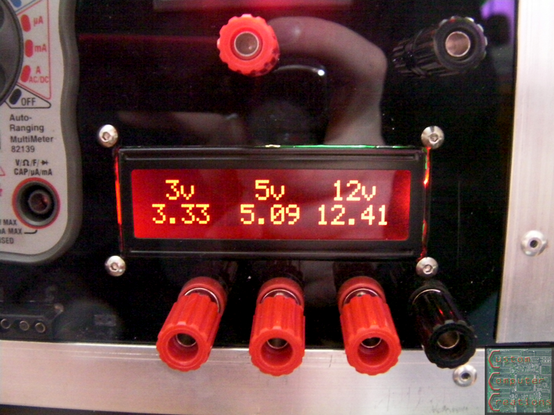
Well I got the code sorted, just needed to make some final adjustments.
the code:
And the final result. It is accurate to within 0.05v, which for what I'm going to use this for is more than accurate enough :DCode:/*Arduino Controlled Voltage Monitor
Code by Will Lyon 2/28/2011
Code for project Power House on TBCS
http://www.thebestcasescenario.com*/
#include <LiquidCrystal.h>
//Initialize the library with the numbers of the interface pins
LiquidCrystal lcd(7, 8, 9, 10, 11, 12);
void setup()
{
lcd.begin(16, 2); //Set up the LCD's number of columns and rows
lcd.print(" POWER HOUSE"); //First line opening message
lcd.setCursor(0, 1);
lcd.print("Desktop Pwr Unit"); //Second line opening message
delay(5000);
lcd.setCursor(0, 1); //Clear bottom line
lcd.print(" ");
lcd.setCursor(0,0);
lcd.print(" 3v 5v 12v"); //Update top line readout
}
void loop()
{
lcd.setCursor(0, 1);
float f = analogRead(0) * 4.92 / 1023; // 3.3 => 9.9
lcd.print(f, 2); // print float with two decimals
lcd.setCursor(6, 1);
float g = analogRead(5) * 8.05 / 1023; // 5.0 => 9.9
lcd.print(g, 2);
lcd.setCursor(11, 1);
float h = analogRead(4) * 20.88 / 1023; // 12.0 => 25.0
lcd.print(h, 2);
delay(1000);
}
Now all that's left to do is make the back door, and wait for my 12v to 24v converter to show up!
So, are you going to leave thr voltage connectors the way they are, or dye them?
Looking at the perspex hole for the LED you can see excess glow around the edges of the module - A few pieces of basic black electrical tape would quickly take care of that without causing any hassle if it needed to be taken apart again....