Re: Project : XTC Retro Laptop
Kudos to that man! It is the first XCom and yes it was squad-based. The second one was as well but the third had an option of real-time as well. For what it's worth though this is by far the best one :D
The game (for those who clearly aren't familiar with it :D) comprises a geoscape part where you build bases on the globe, shoot down UFOs etc. and then the turn-based tactical part where you clear said UFOs of any other aliens.
The battlescape (the strategy part I'm recreating here) is made up from a selection of 10x10 tile blocks and range from 50x50 to 60x60 (so 5 or 6 blocks wide) There are a great deal of different terrains in the game including desert, mountain, arctic, jungle and all sorts. I've gone with the most commonly occurring and therefore easily recognisable farm terrain though.
Below is a screenshot of the UFO I'll be building, the large structure I've made (on the right) and some of the scenery I'll be fleshing it out with. The stone wall in the sketchup will be the stonewall in this image for example but the ploughed field I'm using isn't shown in this image, nor is the small toolshed I've built...
Re: Project : XTC Retro Laptop
Just a quickie with a few pics before I go crazy with getting these walls together. Finally the time is almost here for the fun part of this build, the UFO! First I've just copy and pasted my solution to the power button relocation from another topic here for posterity sake. Then there are some pics of the finished planking, prefab walls and general setup as it is now.
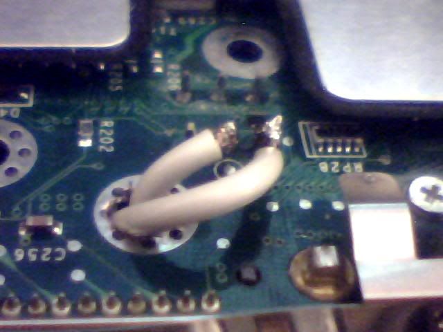
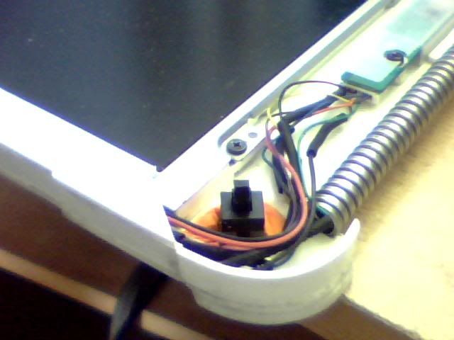
First the power switch. Here's the underside of the board, 6 pin arrangement visible in the top. There are my 2 wires and the enlarged mounting hole I've run them through.
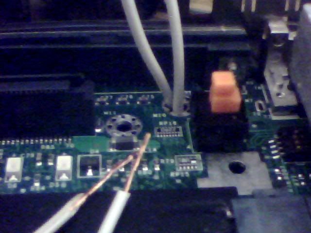
And here it is from the top where you can see the switch itself and where the wires come out right next to it. The black plug just on the left is where the monitor cables leave the case so the switch wires will go that way as well.
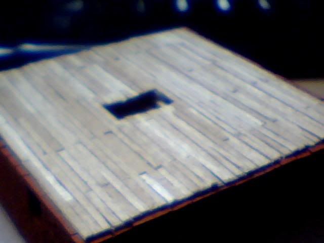
Here's a pants image of the finished planking of the 1st floor. Where's all my hard work gone to :p
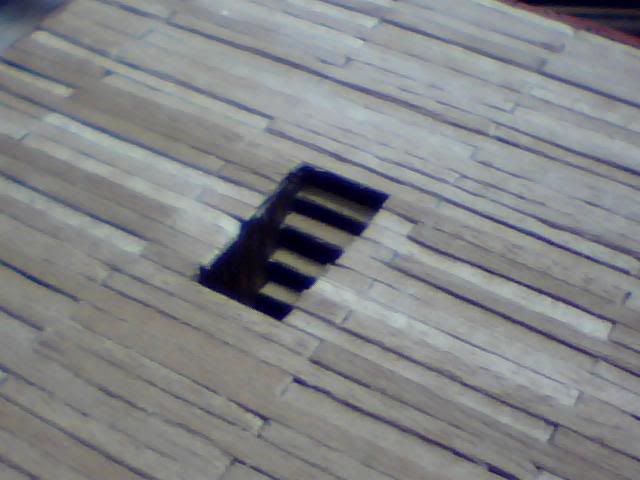
Here's a closer shot showing the stairs but I didn't have a light source to show it off much. More detail visible here though...
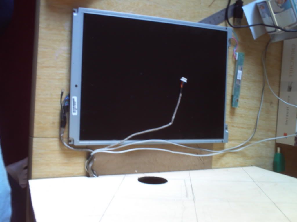
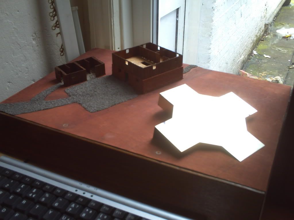
Below is how I've decided to position the screen. It may look very high off the base but remember the roof of the large building is about 40mm. I've already cut the hole for the wiring to come through and I'll be using that and another similar location on the right side of the case for 2 symmetrical mounts. I'm working on their final design at the moment but think I have it cracked!
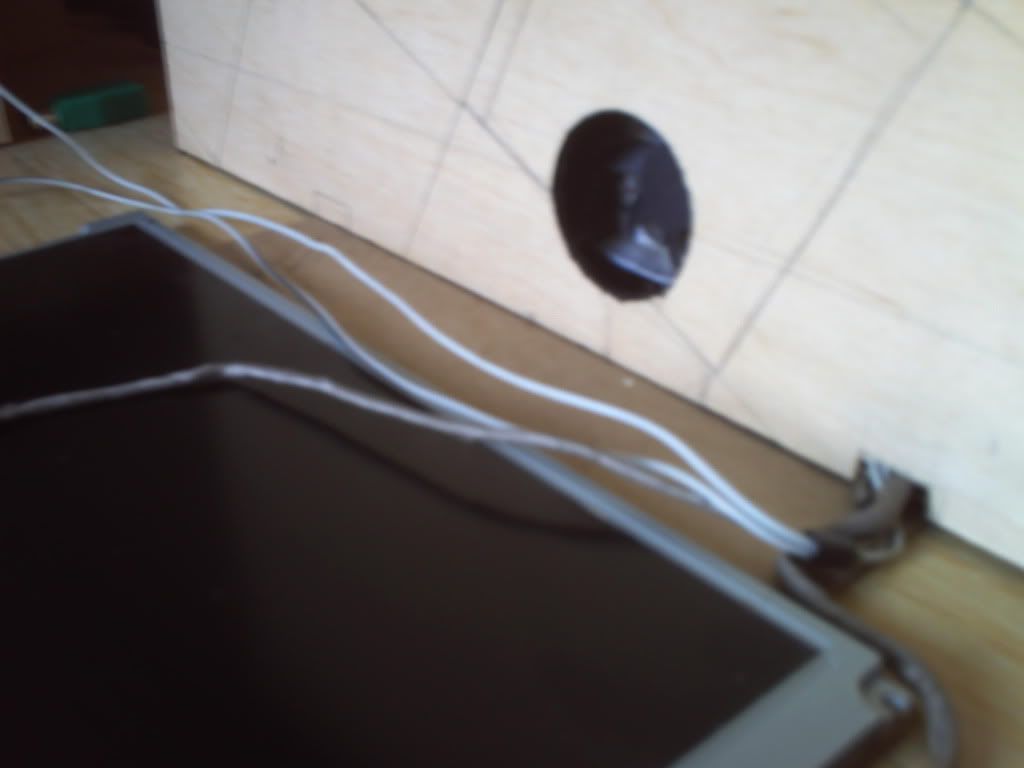
Here you can see the wires exiting the case and the marking for the second support to the top left of the image. The running of the wires in this image closely reflects their final positioning but they'll need extending if I want to keep my screen nice and thin...
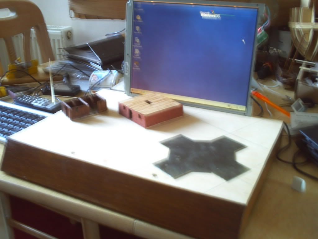
Finally here's an image of all the currently assembled components. I've put on another coat of wood stain here including the edges of the top panel and the underside of said panel is now painted black. I just need to do a little modelling on the top panel now before I can get onto landscaping!
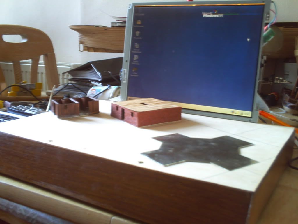
Here's a virtually identical but slightly clearer image...
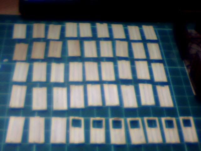
And lastly (I know I said finally already, I lied) here are the walls and windows for the first floor walls of the large barn. They need constructing and staining before I fit them into place and I'm hoping that both these walls AND the planked flooring will all remain removable after this stage of building but only time will tell of course...
Re: Project : XTC Retro Laptop
Ok so not the very next day but it's still the same month so it's close enough for me! Finally got around to building up the walls and they've come out pretty nice. Not too dark so I'm happy with the contrast between brick and wood.
I've also fitted the internal walls so the large barn is nearly done now, just needs some roof supports and of course the roof itself! Would be nice to get the bricks looking a little more aged but not sure how that can be achieved and I don't want to risk messing it up after all the work that's already gone into it!
So anyway here are some pics but this is only a short one as I've been somewhat neglecting it of late! Next job it the UFO so that's the fun bit really! Will update when I make some progress on it but for now there are 4 pics from the game and the model to be compared as you like.
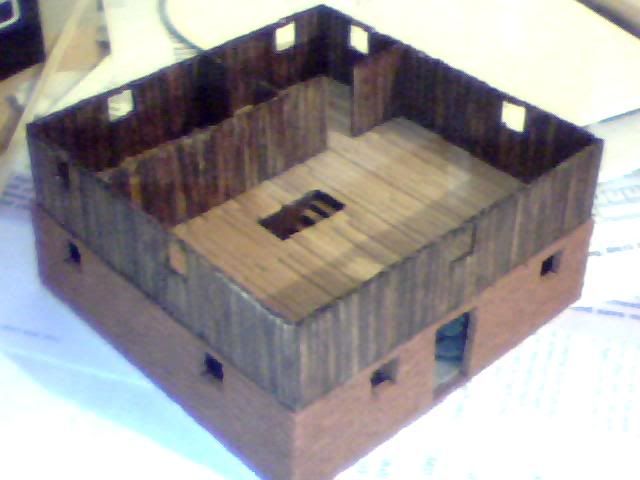
Bear in mind I already know that the top floor is brick in the game but the price of these little bricks is astronomical so it's a necessary adaptation!
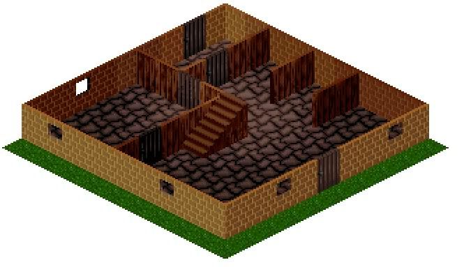
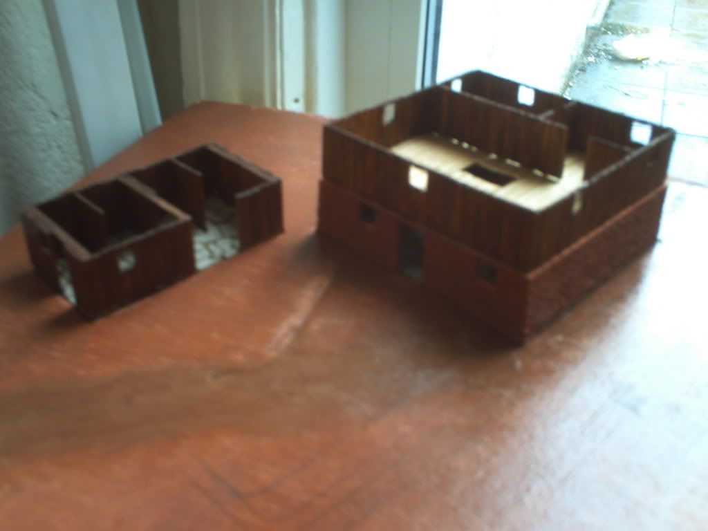
First here is the ground floor from an ingame shot I made
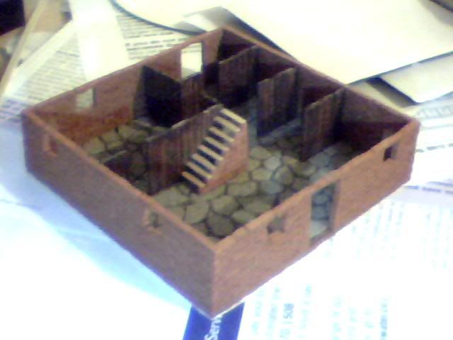
And then the model as it stands...
Now the newly finished 1st floor as seen in the game
And the newly finished model complete apart from the roof beams...
So onto the UFO next, fun but tricky tasks abound...
Re: Project : XTC Retro Laptop
Done a little work on the basic stucture of the UFO today but it'll take some time to get right. Also started working on the frame for the monitor by mounting it on a backplate and it seems like it may not be too big a job after all. Here are a few pics but the below text is copy-pasted from the game's forum so I apologise if any of it is out of context :p
First here's the screen mounted to it's backplate, very early stages but actually seems to be an easier prospect than anticipated.
The white is the plasticard, screen is obvious and on the right is a little power convertory thing for the backlight... Though it's almost invisible there's an additional strip of plasticard below the screen to act as a shelf but it's primary fixing are 4 screws, one at each corner. Another screw secures the bottom of the board on the right and it's kept nice and close to the board with another piece of plasticard to it's right which prevents the top moving right as the wires want it to!
Here's exactly the same image but with the template for the finished work in place at the front. I need to fill 7mm of gap before I start putting the detailed front panels on but it shoudln't be too big a job. It's already as sturdy as it needs to be so I'll just build the rest kind of like a box! If anyone has some buttons laying around that could work as the level up/down or 'OK' switches that'd be great as I don't have anything suitable yet! Note the up/down are slightly recessed so normal keyboard ones aren't ideal...
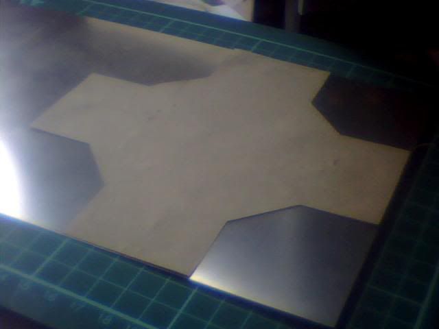
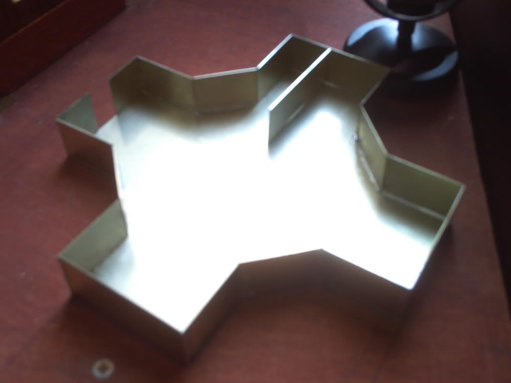
NExt I have a few pics of the UFO itself starting with the template and initial cutting of the floor-panel from months ago! I just cut out a paper template, glued it to the metal then marked round it and cut her out! Soemtimes the simple plans really are the best!!!
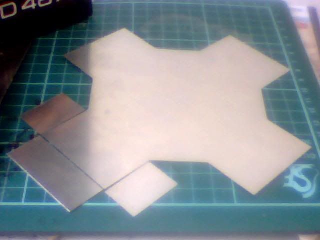
I cut a strip of 20mm high sheetmetal to start making the walls yesterday evening but only just tidied up the edges today. I had about 200mm of the stuff from the first length I cut but for now I just used 110mm of it to test the theory behind UFO construction on one corner of it!
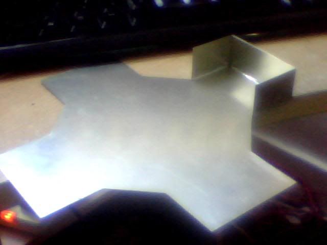
Remember this is the inner wall for the craft as the outer wall will be curved as it is in the game. Not looking forward to trying to get that right mind you! Anyway this means the inside needs to be as neat as possible but due to the underfloor elements I'll be detailing later it doesn't matter so much at the bottom. With these needs as guidelines I soldered the bottoms of all 3 pieces on the inside and did the corners on the outside. I used simple tape to hold the pieces in place while I worked and while it did the job nicely it has left some nasty residue thanks to the heat so will need a lot of work to get the shine back in places!
The images are as good as always so it's hard to tell what it really looks like but I'd say the finish is 'adequate'. It looks a bit messy but ultimately the only part of this construction that will be visible is the inside walls and they look perfect so it's good enough!
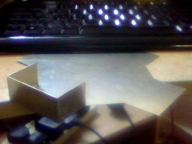
Finally here's one of it upside down to give an idea of the completed model but of course it's hard to tell while it's so incomplete. The roof will of course have the square tiled pattern on it and most of it will be missing completely to allow a nice view of the interior. The walls will be round and the whole thing will be detailed with the doors and 'windows' etc.
Anyone who spent more than a few seconds comparing the images in my last last post will have noticed I'm lacking one thing in comparison to the ingame sprites and that's the height:width ratio. The game tiles are only about 1.6 times as high as they are wide, whereas mine are 2x as high as they are wide. That gives me narrower and taller buildings and details but although it's noticeable I think it'll still give me a result I'm more than happy with.
The UFO will be the biggest contrast as in the game it appears very long and wide but quite short. Mine will of course be taller than the in-game sprites but hopefully it won't be too great a difference. At least at such an early stage as this it would be easy for me to shave off a few mm to bring the height down if I deem it necessary...
Tell you what though, this will be the only UFO I construct loyally and from metal :D It's going to be hard work, use a lot of tools and take a long time!!!
Re: Project : XTC Retro Laptop
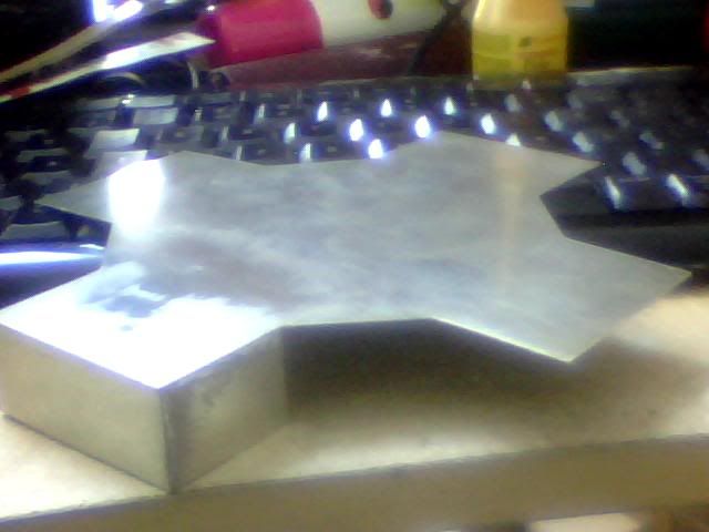
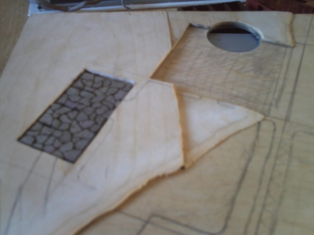
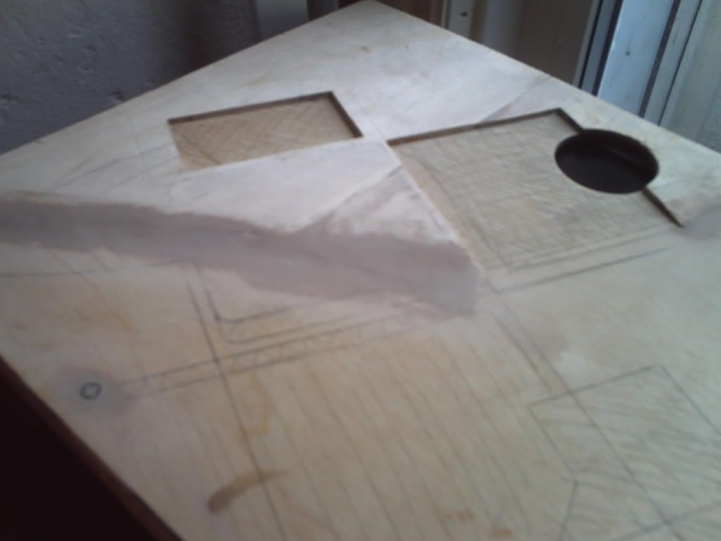
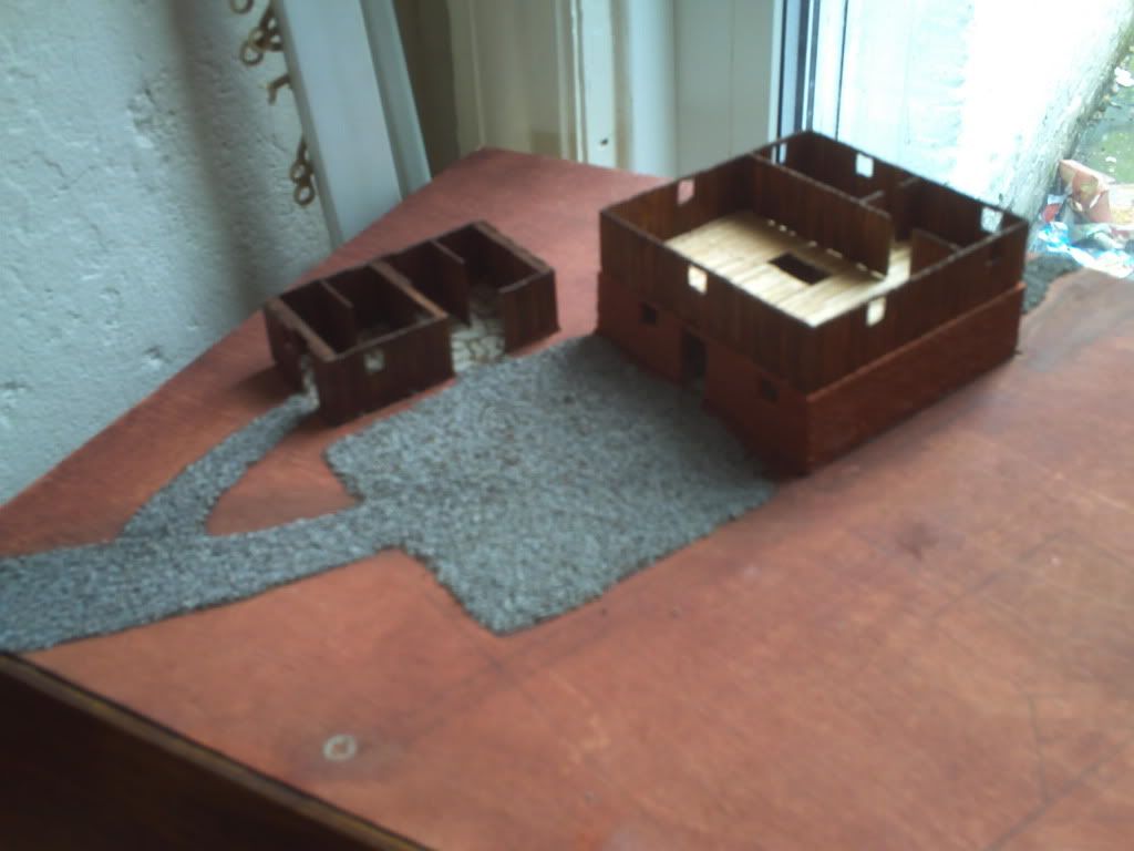
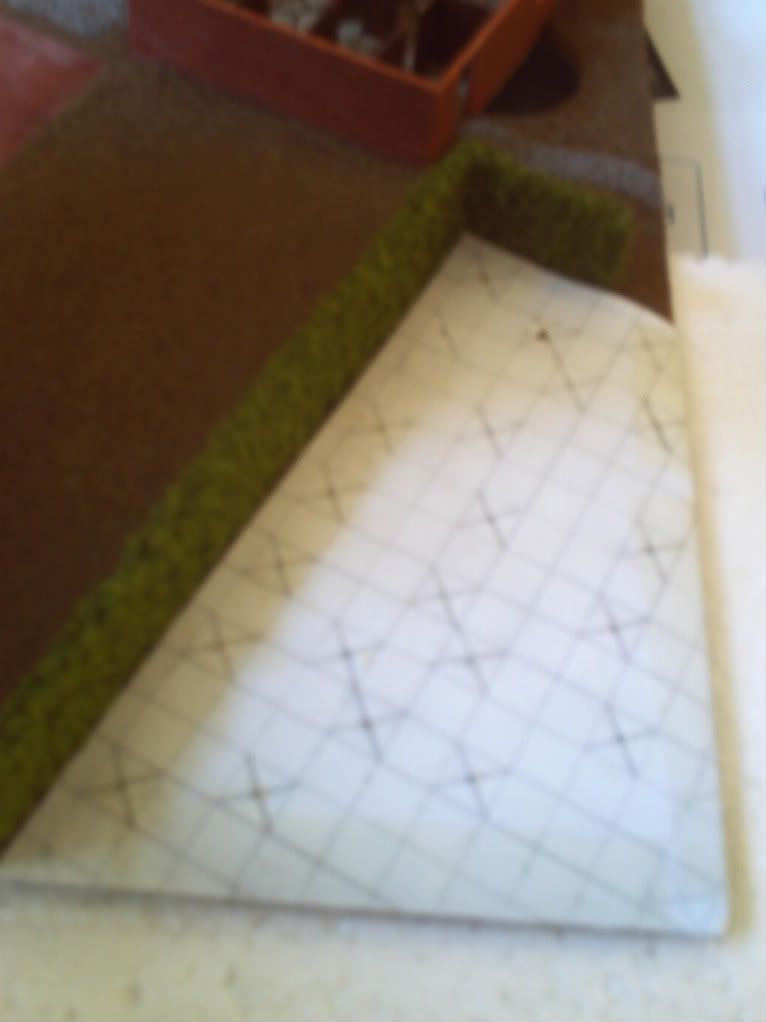
Ok here's the next update (copied from strategycore :p) and the first few steps of turning a wooden board into an X-Com diorama! First problem to overcome was the depth of flooring in the buildings I've constructed, it adds an extra 2-3mm of unwanted height to them as previously mentioned... Luckily I had some of the wood I used to build the case left over as spare so I used it to fashion a sort of 'hill' on the left side of the case which can be seen in the first few pics...
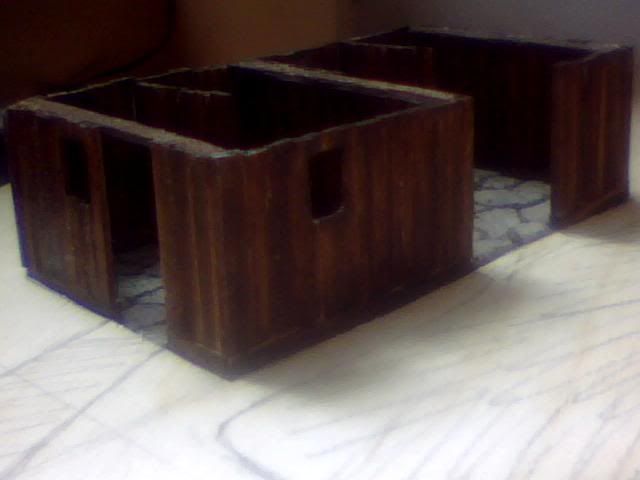
Here are the 2 pieces I used before being attached and with the buildings removed so you can see the recesses that will hide the extra height for me.
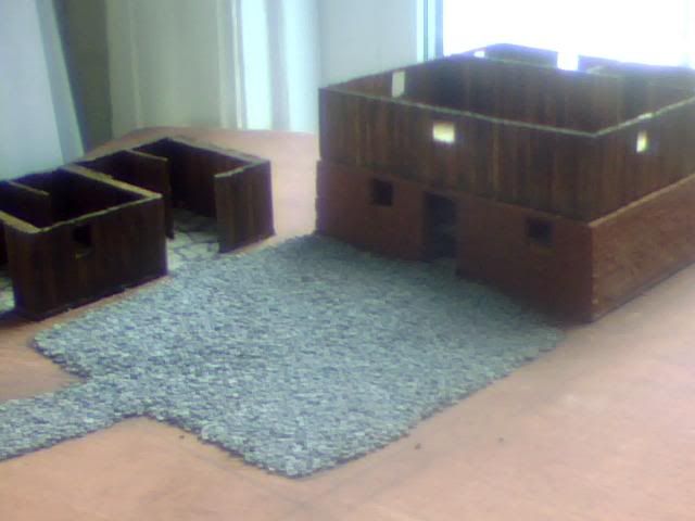
Here's a low view with the buildings in place, the edges have been sanded to quite an angle but will also be filled shortly to achieve the gentlest possible slope.
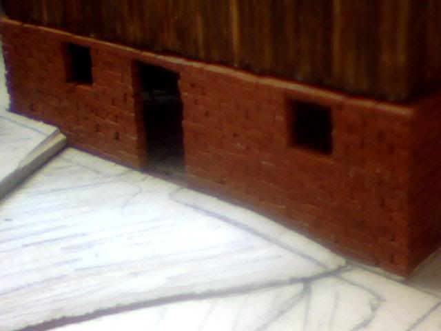
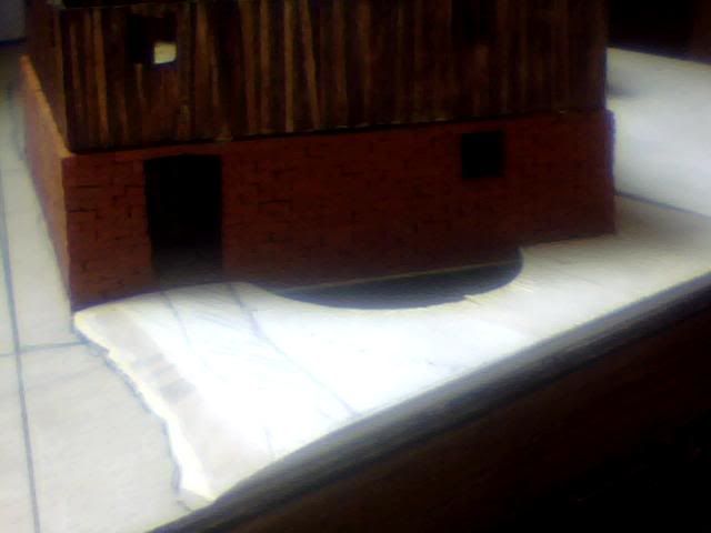
The front door to the larger building shows the level somewhat.
And a shot of the small shed does an even better job of it.
Behind the large building, I had to recut the hole for the CPU fan.
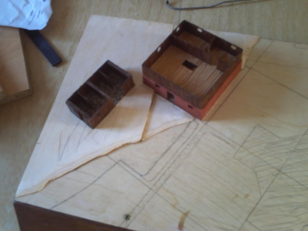
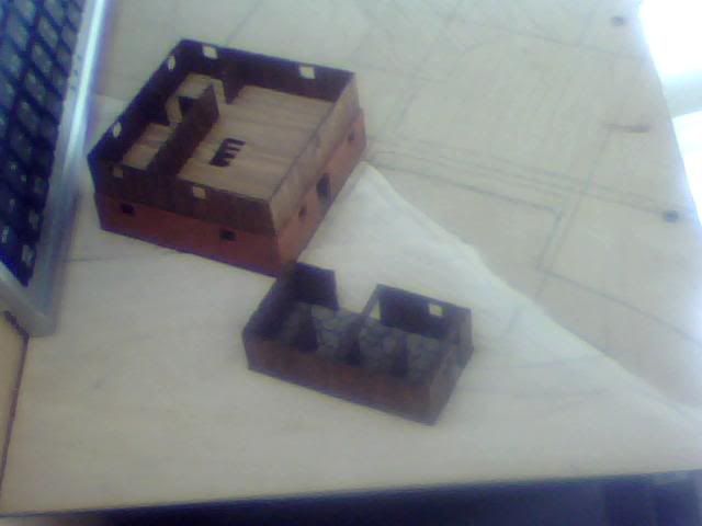
Here are some overview shots of the new landscape and one in which I've removed everything but the stone floor of the small shed for comparison...
After 8 pictures of the above I only seem to have 1 of the filling but it was a fairly straight-forward and boring process of fill, dry, sand. I only used a single coat as there will soon be paint, dirt, gravel and grass on top of this whole board :D
I seem to have slacked off with pictures of the board painted too but again it's only a minor change in colour so nothing interesting anyway!
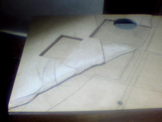
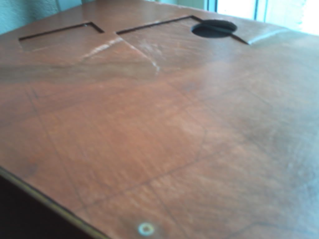
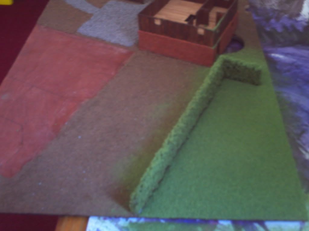
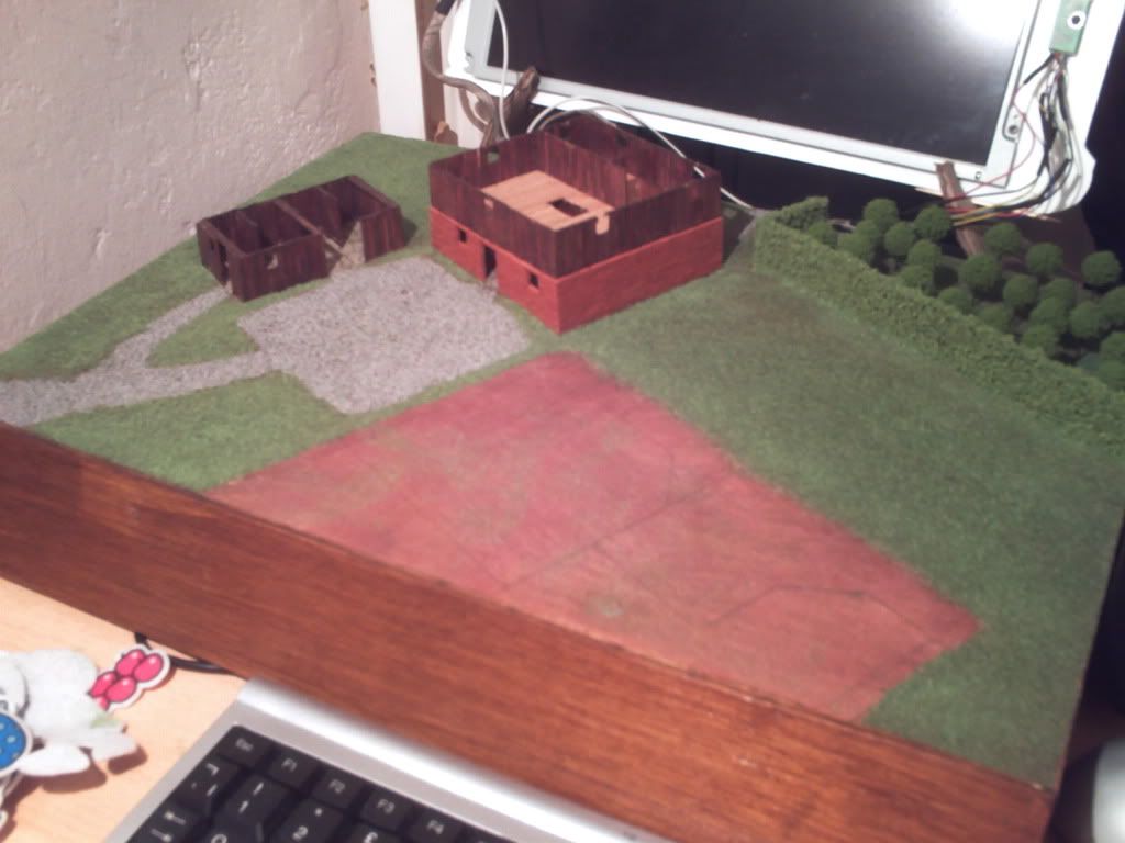
Here's an image with the hill completed and the whole board ready for further detail. Thankfully the lines I drew on earlier are still visible. For those wondering why I painted it brown when it's all going to be covered up, it's just in case I lose a lot of topping over the years. Brown spots will be practically unnoticeable while the yellow-white of the wood could detract from the remainder of the case considerably...
The last job I did before this update was to lay the gravel on all areas that needed it and I have a massive amount left so will have to think of another use for it at a later date! I mixed up a thin water/pva mix first and literally painted it onto the areas I wanted to detail, first laying down a coat of soil and leaving it to dry overnight.
Sadly I have no images of the soil and after I laid the gravel this morning it's practically invisible but I laid it for the same reason as I've done most thigns here the way I have. Just trying to bring as much realism to the scene as possible! Also I'm sure the soil will become more visible with time as the gravel begins to deteriorate. It will add to the natural look of the scene rather than being a hard-edged effect and I may also deliberately thin the gravel down in areas later to simulate frequently trodden paths. Anyway here are the last pics of the gravel being laid down, none of the process all of result!
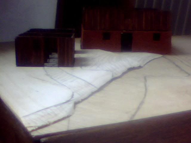
Here is the area I marked down for gravel with a main access to the front, pathway to the shed and entrances to both buildings. There is also a small path leaving the rear of the large barn.
Here's a slightly closer image of the courtyard area (yes I know, not true to the game but give me a break hey :P)
And finally a super close up which was intended to show a few areas where there is some soil showing through the gravel. It's hard to see but basically the darker areas are soil...
I may detail the gravel further once the whole case is complete as it's all very light in colour and a little too uniformed to represent realistic gravel. For now though it's worked out just as I'd hoped and the slope of the board has become a very gentle one as desired so success up to this point!
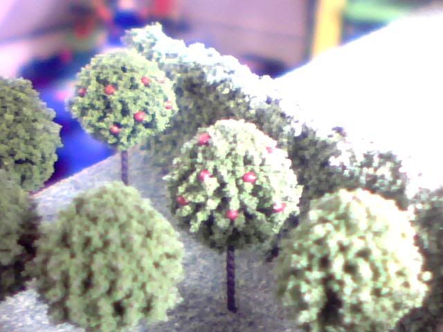
My next hob is to fill in the remaining gaps with soil before 'sowing' the grass! I'll post some images of that when it's done, probably over the next few days. For now I'll be leaving the 'field' area where the UFO will be crashed and the top right section of the board will now most likely house an apple orchard with a surrounding hedge like the one in the game. I'm struggling to source small enough trees though as they need to be between 20-30mm high at the very most and all the models I can find are about double that due to being based on full size trees rather than the small ones in UFO.
Anyway here is a final image just to round off the update. This is how we're looking so far but the UFO is upside-down so none of what's visible in this image will be when it's done! I've placed it here to illustrate how it ould look if placed at an angle though and I'm pretty pleased with it as an idea so I'll probably 'crash' it through the top of the case so it case be partially buried. Right now I'm concentrating on everything BUT the UFO while I wait on some better solder though as the job thus far has been a nightmare and I want to keep the joins as clean as possible...
Please comment as feedback is part of the reason I'm sharing this build :P
Re: Project : XTC Retro Laptop
here's the results of a google search for z-scale trees.
http://www.google.com/search?q=z-sca...72de1d&safe=on
that was just a quick search, but it looks like z-scale model railroad trees are just the right size for what you are looking for.
Re: Project : XTC Retro Laptop
Wow never heard of z scale but 1:220 should certainly provide some nice small models of big trees! If I can find some decent looking models to start with I could use small beads or ball bearings to make my own fruit to match it to the rest of my 1:100 stuff :)
I've laid down all the soil on the left side of the case now and it actually makes it look a lot better compared to the painted wood beneath it. Even without the grass the whole thing is slowly becoming a believable scene rather than just a few models on a piece of wood!
Need to build about 25cm of stone wall soon and I'm not sure if I have enough of the material left over from doing to flooring so will have to wait and see... Was only a few quid for a big bag so not the end of the world if I need to buy another one, not worth compromising on a crappy resin wall when everything else is getting so much detail given to it I think...
Re: Project : XTC Retro Laptop
yeah, when i started looking at trees for you, i looked at n-scale, but they were all 30 to 70mm tall. the z-scale stuff looks like it's all 25 to 40mm tall, so it should give you a good variety of sizes to match your "model".
Re: Project : XTC Retro Laptop
Found a few 30mm ones on ebay but they don't look as great as I was hoping they would... Also still on the lookout for a suitable hedge as without that there's no point attempting the orchard at all.
Currently shopping for suitable scatter for the grass as well and still haven't decided on the minis I want to use. I only need 3 different types but nothing I've found is quite right. I need armoured soldiers with no helments but I think I'll have to buy helmet'd ones and then seperately buy unarmoured civilians for a head transplant. Same sort of scenario seems likely with the aliens so looking at about £30 for over 50 miniatures when I only really need about 10 :(
Re: Project : XTC Retro Laptop
For the hedge you could take a sponge cut to shape and paint it.
Re: Project : XTC Retro Laptop
Yeah I'm stuck between the thought of making something myself and it never being good enough for me to be happy with it or buying something (if I can find it!) and still not being happy because I ddin't make it myself haha
Re: Project : XTC Retro Laptop
I'm really ready to go to bed now but I've been neglecting this log for a while so based on today's progress I think it's about time to bring it up to date!
First thing I finally got round to finishing up was the UFO walls whcih gave me some real trouble. Even with some high-flux solder it was a nightmare trying to get it to hold a shape I was happy with and I substituted the tape I was using for temporary support for superglue here. The tape tends to melt and leave a nasty substance to remove, the glue however is highly noxious and evaporates under the heat of the iron...
Either way I finally got all the walls in, the final shape of the craft has it with a curved exterior wall but the inside is pretty much finished now (I think!) Anyway, here it is with the walls up, the internal one is not attached but is in the right place...
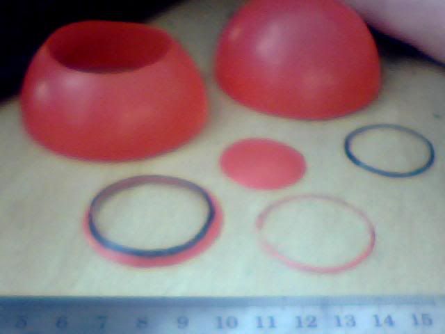
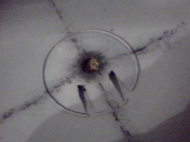
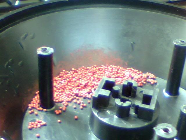
Next I got to work trying to figure out how I could detail the interior. I came to the decision that the craft would be powered by 5 grav-wells (one on each end of the 'X' and a 5th in the middle) with the power source located directly above the central one. In the game however all we know is that that's where the power source is, noone has ever seen under the floor of these things until now ;) I set about making the central grav-well which would be visible but lacking anything metal to use I cannibalised one of my son's plastic balls.
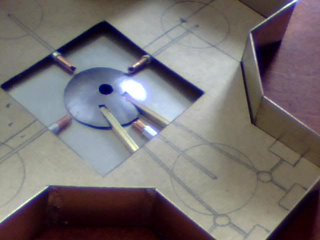
I cut another small hole in the top of the disc that would form the grav-well to replicate the former position of the power source and then attempted to paint it silver to match it with the real metal. It looked crap and was never going to work but I had a play with some other details to see how the layout looked best and came up with the following arrangement. The 4 pipes are conduits for taking whatever energy this ship uses from the source to the outer grav-wells while the bars lead to the navigators' control panels and carry optical inputs (apparently)
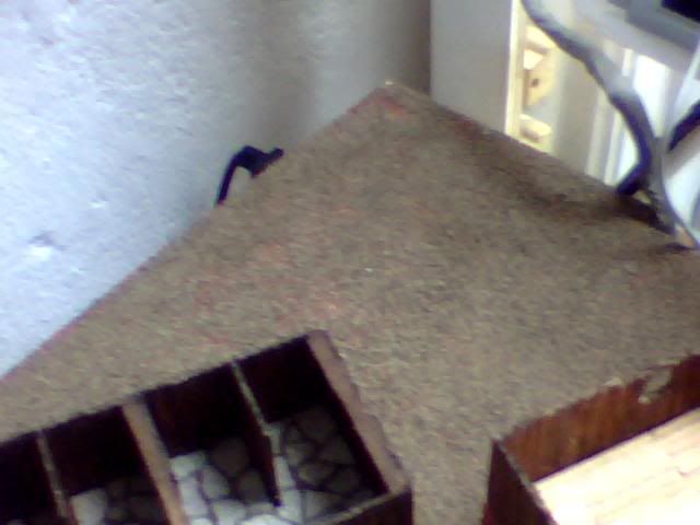
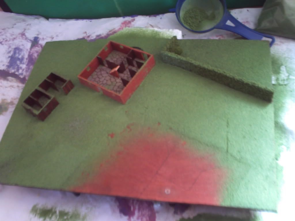
I laid down some soil next but only did the left side of the board and it turns out the method used was fairly sub-par as it didn't hold as well as I'd hoped. When I returned to lay the stuff on the right half of the board I used a different method which was far more successful so I scraped off the loose parts on the left side and redid them too.
(Patchy bits)
Now I have a long wait for my scenery to arrive (this is about a week ago I guess) so I went back to the UFO detailing as I knew it'd be put off forever otherwise.
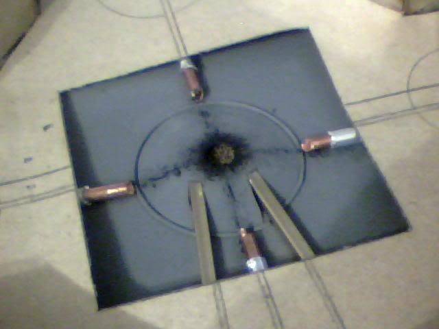
With the silver paint looking crap and cheap (brush-marks not helping) I looked for an alternative way to match the grav-well with the base and also hide the join between the two. I decided to spray the under-floor part of the ship to tie it all together and avoid brush marks but had to go with a dark grey as I have a limited selection of colours in cans! The below is the first attempt which came out badly but the colour works fine being very close in fact to the in-game palette.
As seen in the above image, I used some thin wire to conceal the join (solder actually!) and then I sprayed it again for a better coat.
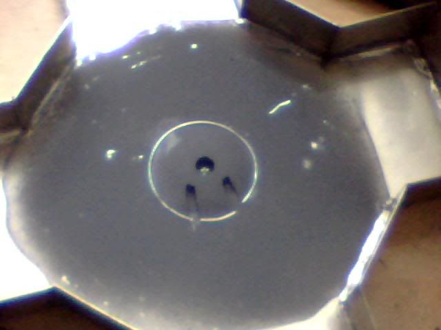
Feeling much happier with the finish I blobbed some black paint inside the grav-well and followed it with some soil while wet to simulate looking right through the bottom of the craft (remember that's a hole there now the power source has gone poof) I got some black on the top of the well so went with it and added a little basic detail.
The lines are again to simulate the power conduits and help give an idea of the vessels original layout before the explosion. Here is a shot with the fiddly bits back in place for a quick check up on progress. Looks good but doesn't look like a massive explosion has gone off so will work more on detail later!
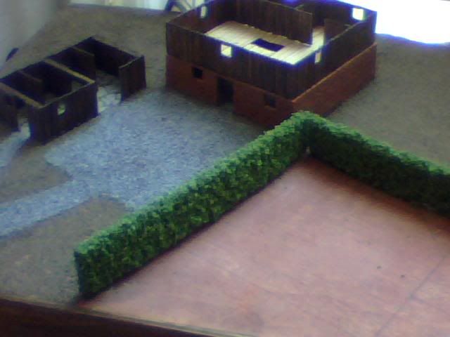
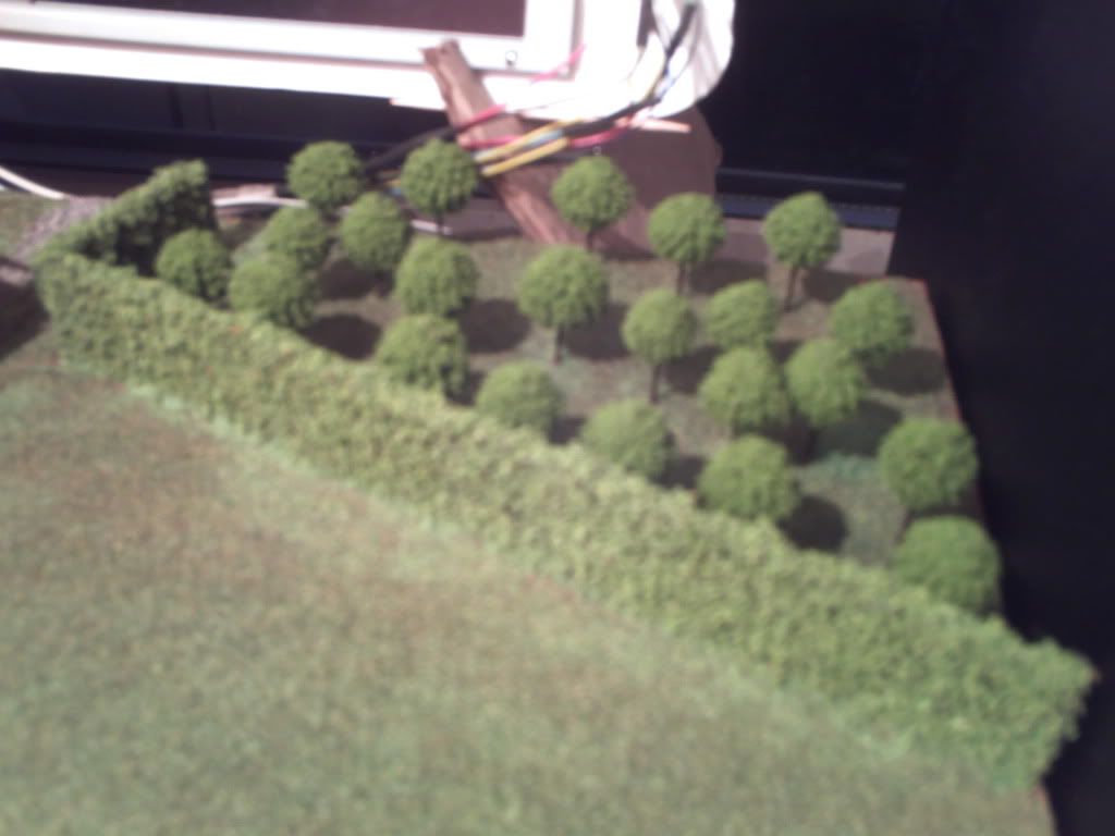
Finally, just a few days ago, my delivery of scenery arrived! But I was on the grinder so I missed the postman and had to wait another day to collect it :( But I got it yesterday and boy was I busy today! I got trees, grass and hedges from these guys and all of it was custom made so sadly not cheap (cost about the same as the laptop but then so did the bricks!!!)
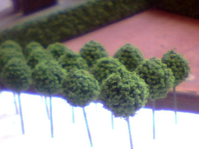
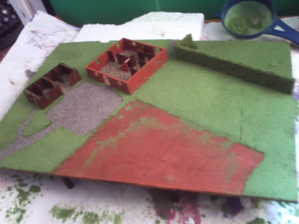
Here's the hedge set up in the wrong place just for a photo-op, dimensions are perfect and the trees are spot on too, just missing little apples but I'll need some VERY small beads to make them!
I measured up the hedges first and formed them into one continuous piece before attaching the whole lot to the base. Then with the assistance of a simple paper template (based on the positioning of these trees in the game of course!) I drilled 1mm pilot holes to shove the trees into!
With the holes drilled I treated the orchard as a spot for testing the flock and it came out pretty well. I think I took this after removing the excess but it's thinned out a lot more since then and will continue to do so for some time I'm sure!
Happy with the grass I moved onto the rest of the farm but not before test fitting one sole tree. It looks perfect but the trunks are a very lame and pale brown so I repainted them all with a darker colour for more contrast and (you guessed it) accuracy to the game sprites!
After tipping and tapping most of the excess grass off my farm I ended up with this so it was out with the brush to mow the lawn.
People recommend soft make-up brushes for this but I had to resort to a 1" paint brush! Either way I was careful and it turned out fine.
After the final brush off I fitted all 22 trees very carefully but still lost a lot of ground cover in the process. The holes I'd drilled were very snug as intended but that meant there was a lot of pushing and pulling involved to get them all through and the shock did remove a fair bit of foliage.
Regardless though I've managed to do all the grass, trees and hedges today so I'm dead chuffed with where I am! I haven't really got many decent pics as the sun is long gone but here's what I managed. First the orchard just after an apple harvest :p
And now an overview of how the case looks this evening! Just need tops on buildings, a stonewall at the bottom and the ploughed field and of course the UFO itself!
Thanks for looking and let me know what you think ;)
Re: Project : XTC Retro Laptop
Quick question folks... If I want to upgrade the crappy speakers that are in this thing can I just do it? Presumably a speaker is a speaker so just cutting the old ones off and soldering in a newer piece of kit should work shouldn't it? I only want to slightly improve on what's there now so I'm not talking a massive overhaul, just slightly larger, louder speakers (probably sourced from another lappy)
Re: Project : XTC Retro Laptop
probably if they come from another laptop then you could just swap em straight up like you want. otherwise you have to pay attention to the impedance of the speakers.
as an example, if you have a system designed for 4 ohm speakers, you can use pretty much any 4 ohm speaker safely (sound quality not withstanding). you can also go UP in impedance. so with the same 4 ohm system you can use 8 ohm speakers safely. however, you may have sound and volume issues. but it'll work. you can't however go DOWN to a 2 ohm speaker or you risk burning up your amplifier transistors.
you also have to know that impedance ADDS in series and DIVIDES in parallel. so if you have the same 4 ohm system you can take two 2 ohm speakers and wire them in series to make a 4 ohm speaker.
that's probably way too much info for you since you are just planning on using other laptop speakers, but it's good to keep in mind anyway.
i knew a guy i was in electronics school with that wired up his chevelle. he used 4 4ohm speakers wired in parallel for two channels. so that meant that all four speakers divided down to 1 ohm per channel. he therefore blew his nice new expensive amp because it wasn't designed for that low of an impedance.
now, just to qualify about dividing since i know there are others on here in the electronics field, there is actually a formula for determining parallel impedance that isn't just simple division. but as long as you are using the same impedance rated speakers it works out to the same as dividing them in two. it gets more complicated if you run a 2 ohm in parallel with a 4 ohm.
Re: Project : XTC Retro Laptop
Wow, thanks :o That is lots of info but sadly I'm a surprising technophobe when it comes to wires and electricity (look how long it took me to extend the monitor cables :p) I tend to prefer using store bought extensions to splicing when I can but right now I can't so I think I need to learn a little about all those big words you just used :D
Just did a quick google for impedance as I haven't the slightest clue what it is, but the Wiki came up with lots of scary equations so I immediately navigated away :p Do I need to understand what it means or is simply understanding the values enough to get me by here?
Also how do I find out what speakers I can and can't use? Basically how do I find out what it's currently using? Can I find out from the hardware itself or will there be software on the lappy itself that tells me?
Way I understand it, first I need to find out what's currently in there, then determine what my alternative options are for replacements and then it's ebay time!
Re: Project : XTC Retro Laptop
Easy solution would be hook up a set of speakers to the headphone port.
Text pictures:
Code:
Parallel

-  ___ ____

+  ___O____O


2 4 ohm speakers this way makes 2 ohms.

Series:

+   ---O---O----   -

2 4 ohm speakers makes 8 ohms.
Re: Project : XTC Retro Laptop
Thanks AmEv, just checked the hardware and the rear of each speaker is marked '8Ω 0.8W' There's more but the rest seems like manufacturers numbers or something... Now what does that mean I can fit? I only want 2 speakers as I'd like to have ports for them in the angled front panel but does it mean each speaker currently fitted is 8Ω or does it mean that they're 8Ω together?
Just looked some more and to clarify, each speaker is individually wired to their plug, ie. not parallel OR series! I have 4 wires coming from the plug, 2 for each speaker... So can I replace each one with another 8Ω equivalent without difficulty?
Re: Project : XTC Retro Laptop
don't look up impedance, it will scare you.
the 8ohm (i don't know how to make the ohm symbol) mark, means they are 8 ohm impedance speakers. so yes, you could simply replace each one with an 8 ohm speaker.
usually different industries stick with the same style speakers. for example, car speakers are 4 ohm, house speakers are 8 ohm, and there are 2 ohm speakers out there, but i'm not sure what they are used in.
so i would suspect that the majority of your laptops will have 8 ohm speakers.
the0.8W just tells you how power they can handle. you can always go UP with that number. but you don't want to go down or you can blow the speakers. of course i don't think you'll have much luck finding speakers less than .8W, lol.
you could always just get a pair of external powered speakers and mod them to go where ever you want. just keep them wired up the way the are and plug em into the headphone jack.
Re: Project : XTC Retro Laptop
oh yeah, with speakers you only have two wires to hook up. so it's easier than extending a monitor cable. the other cool thing is that if you hook them up backwards (positive to negative and negative to positive) they still work and won't hurt them. but with higher performance speakers (expensive car and house) the sound quality is diminished a bit if they are hooked backwards.
Re: Project : XTC Retro Laptop
Awesome, thanks man, going to do some ebayin' I think! The otehr thing I want to do on the front is get custom grills cut. Is there anyone here who can laser cut some bits out of some nice shiny metal for me without wanting loads of money for it? That'd be nice ;)
Re: Project : XTC Retro Laptop
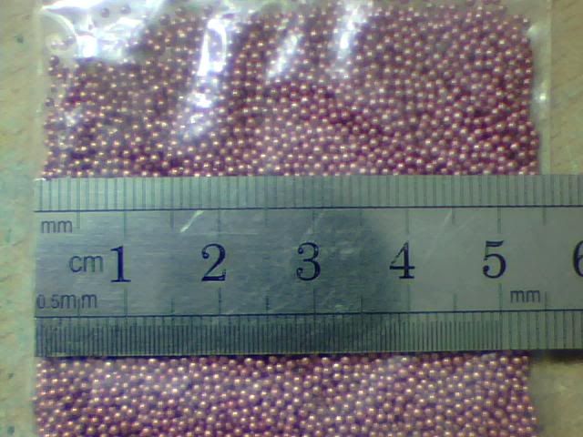
It seems I've neglected this thread longer than I thought but I've only just sat down to progress on it so not much has been missed. The only thing I did some time ago was to start putting the apples on the trees! It's a very slow process but it looks perfect so it's well worth doing. Here are some typically bad pictures of the first few I did but I now have half of them finished. I used little 0.5mm fimo beads which I painted in a dish before individually securing each one with some simple PVA (white) glue!
Here are the tiny beads I used before they got painted a nice dark red...
And after! Forgot I took this pic...
And finally here's the end result of the first few trees.
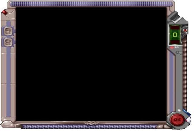
But anyway, that was done a long time ago. I've been working on the Mammoth Tank project lately so this has been sadly neglected! Some of the guys on the X-Com website have been bugging me for progress though so I thought I'd have a go at the screen. It's come on pretty well but it has practically no detail so far. Just the easy bits done...
Here it is anyway, I'll explain the steps as I go! First off here's a shot of what I'm trying to recreate. It's the in-game graphic which surrounds the map of the tactical levels, though I've resized it here so it fits my screen without looking totally out of scale...
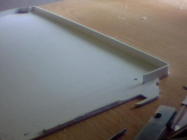
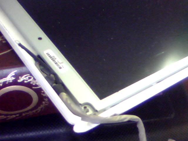
I started off where I left off a few months ago when I'd cut a couple of pieces but not done much with them. One long straight piece needed to be curved and fitted to the backpiece to create the left most part seen here.
This is a closer shot of that same piece and it also shows a few metal pins that I've used to replace the screws in the two left holes. They'll be sandwiched between the top and bottom parts of the case and the open ended locating holes on the screen will simply slide onto them like locating lugs!
Here's a shot of the top piece which had corners at both ends. It took a great deal of holding and clamping and such and no small amount of patience on my part!
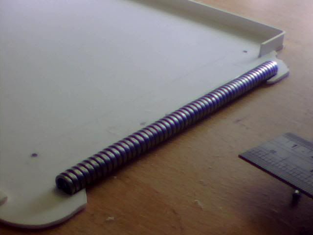
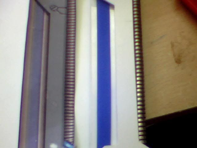
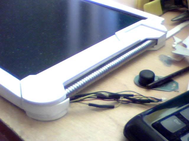
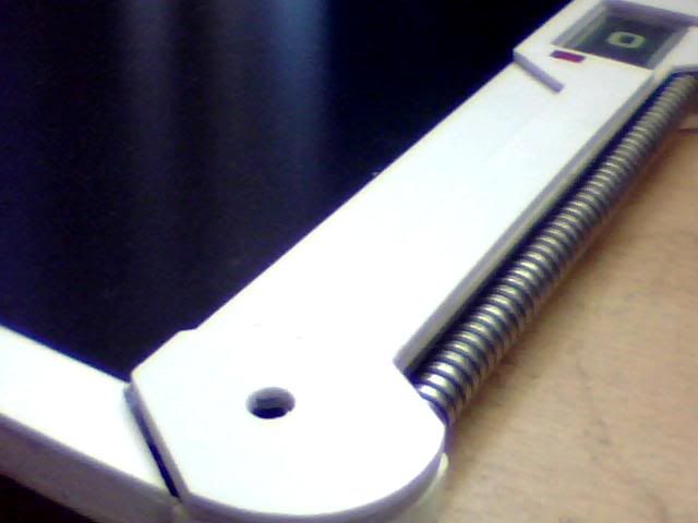
On the right side of the case is a wierd looking wirey type thing. I have no idea what you'd call it... For me though it looked kind of like convoluted plastic tubing so I tried that first. It probably would've been ok but isn't too easy to work with as it comes off rolls. Not ideal for making straight lines! Thankfully I was sent some pressies by a very generous Frenkie after I commented on the metal pipes he was using for Project Charge. So I cut a length from one of them and used that instead for a perfect result!
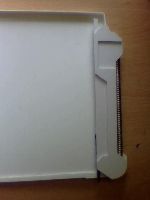
Next I decided to cut the most complex pieces of the casing, the darker grey part on the right hand side which enclose the pipe and displays and such. These parts form a primary handhold (in my opinion!) and are thicker than the rest of the assembly so it took a few layers to make it right. I ended up making one bottom piece to extend the grip out to the rear and a second piece to form the top of this side of the case with a third one to go atop this one and form the front of the grip.
Here's what I mean by the two top pieces, the larger one forms the whole side of the case while the smaller top piece is just part of the grip.
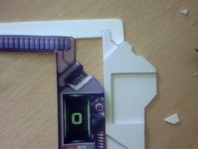
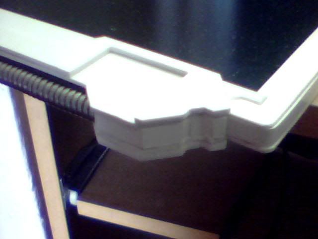
The top front piece of the casing was easy to make and can be seen here. The funny angles I cut into it can be seen on the adjacent image so they were necessary. The image also illustrates the purpose of the gap which will house a display (which will be artificial)
I started to think a little bit about the various detailing next and that includes the buttons on the left, the power (OK) button on the right, 3 pieces that look like lights, the '0' display and it's neighbouring mechanical part and finally the blue stripes... I figured the blue stripes are raised friction material or similar... I went to the cheap shop in town and picked up a few bits for the mammoth tank and got hold of something that was intended to put hot pots on I think... I chopped a few strips out of it to get the material I needed and this is one of them in place (mock only)
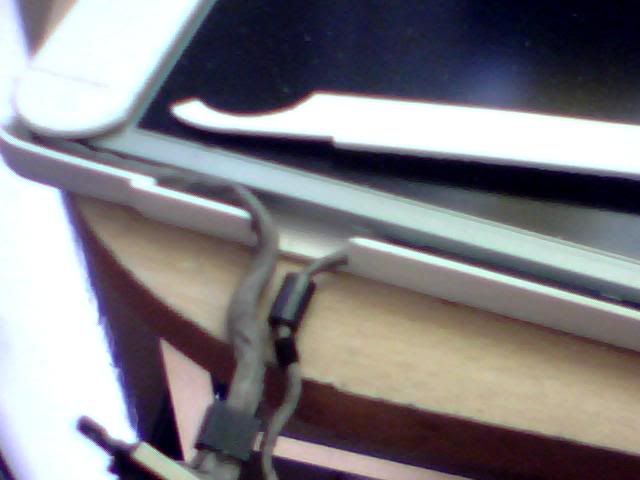
About this time I decided to continue building with the screen in place. Here it is with the cable plugged in but not much else.
This is the bottom after a lot more work has been done. The left side piece will clamp the lower pin in place and the piece visible in the middle of the picture is the bottom piece. It's removed here to show where the wires run. The 2 for the power switch aren't in place yet.
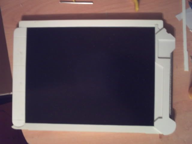
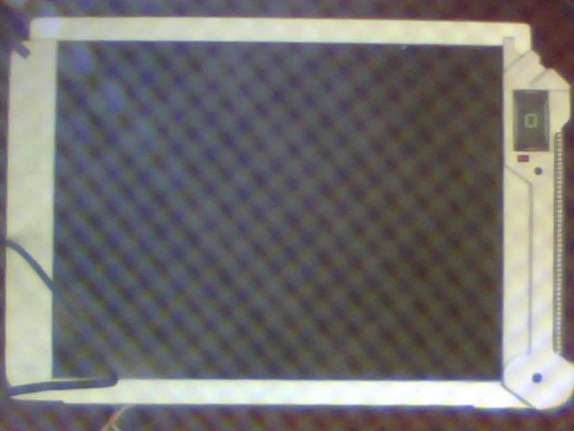
I seen to have skipped a few steps but here is the current state of affairs and I'm pretty pleased with it! All of the sides are in place (though I'll fit a final piece behind the metal pipe as there's a gap right now) and all the top pieces are cut too. It's all about detailing now so I'm going to get on with that now.
HEre's the right side where I faced the most serious curve of the project! I left it overnight and it's not bad this morning, will need a little fine tuning though... These wires are way too long so will need cutting again and soldering shorter. I'll add the wires for the switch at the same time but right now I don't HAVE a switch... The silver thing seen to the right is the innards of a 'dog clicker' used for training I think. I was hoping to use it as the top part of a switch but it's too big and would be in constant contact with the earthed screen. While I could make that work I'd rather keep it as a separate circuit and use a simple 2-wire switch so I changed plans...
Last image of the day, this top piece will need some filling and shaping as it appears to be a vent or speaker in the graphics. It can wait till later though!
Will update again when I manage to figure out the switch and buttons and such. I can't really finish assembly till those bits are done though and I need to be thinking about painting too but that needs the whole assembly to be complete so I can fill and sand it to a nice finish first.
Meh, I'm off to dismantle some hardware for switches anyway! That's something I'd like to get done as soon as possible. Will post progress when I have some but I'm working on the tank as well so won't be too soon!
Re: Project : XTC Retro Laptop
damn man, you are very skilled with modelling! :up:
Re: Project : XTC Retro Laptop
Thanks Billy! Certainly most of this build does come down to modelling as the components that can be considered the actual 'case' were relatively simple, especially with an old lappy to start with!
I've actually updated this worklog on the X-Com website since my last post here so I'll share it here as well seeing as I'm posting anyway :D Prepare for some Ctrl+C, Ctrl+V action!
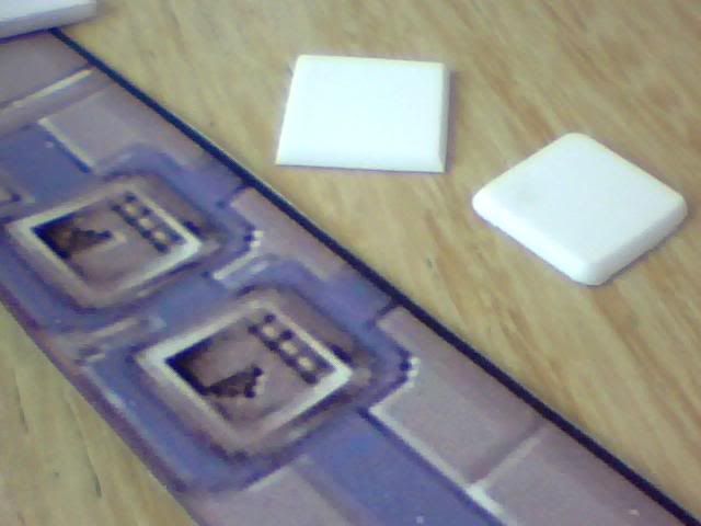
I finally ran out of patience in my search for small keyboard buttons or similar for the up/down level buttons and made them from 2mm plasticard. I cut and shaped them first...
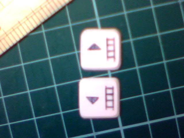
Then carved in the appropriate design and painted them accordingly...
They came out pretty well but I need to thicken the lines that make up the ladder at some point.
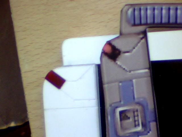
Here's my new switch held in place by something called sugru which is a kind of moldable silicone...
I continued with the detailing by creating the small red lights of the design. I cut away some material from the plastic pieces and then used parts of an old cd case to make the 'glass' bits. The back of the pieces then got painted red, a lighter colour first for the 'highlights' seen in the graphic and then darker red to finish the job. It's possible that the backlight from the screen will light these pieces but it's unlikely. It wasn't part of the plan anyway so it doesn't matter either way...
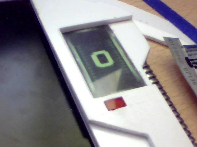
In addition to the top-left light there is also one under the level indicator on the right which is presumably a power indicator (as it has 'on' written beside it) I made that one in the same way and then added the indicator above it. I cut a hole from the top piece of the case (not the top of the grip) and fitted anotehr piece of plastic cut from a cd case for the display screen. I used the LED panel from my template and then backed it with some card to keep the whole thing together.
Moving on I figured I could recycle part of the lappy to make the 'screw' fitting nearby. The reusable part in question was a round sticker which had initially covered a screwhole in the laptop case. I cut it in half to create an imitation screw head and then drilled a shallow hole to accomodate it flush to the rest of the grip. I cut the marks into the grip for the selection indicators (for whatever this screwy thing is!) and that was it.
Also in the above shot is a shot of the vent/speaker thing which is almost finished. I cut a notch out of the topmost piece of the grip and then filed a chamfer into the edges. To finish it I need to drill 4 rows of tiny holes on the next piece down. Another job I did which I didn't take any pictures of was to secure the metal pipe in place. I happened to have a long narrow piece of styrene that fitted snugly through the entire length of it and then glued either end of this to the back of the case. It's now totally secure.
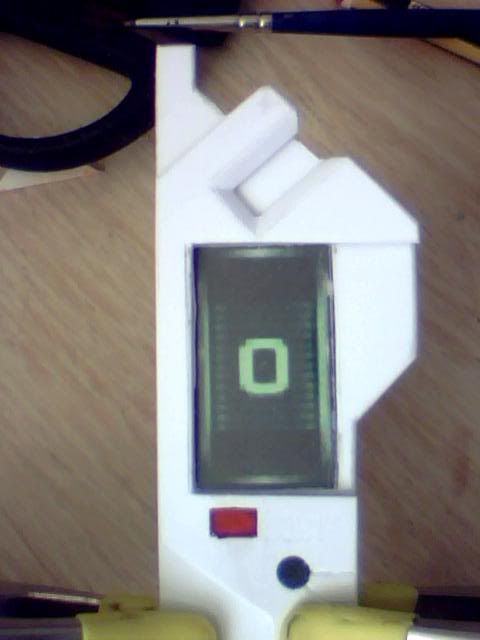
I tried desperately to get a new picture of the overall appearance because I've gotta say I'm pretty chuffed with it! My crappy camera was just giving me bright white shots though so I failed miserably. In the end I used a 'splatter screen' bought for use in the mammoth tank to diffuse it slightly and got this half-arsed image to show...