like the idea. you should fit a watercooling block over the drive, or around the gel packs to keep it all cool.

Printable View
like the idea. you should fit a watercooling block over the drive, or around the gel packs to keep it all cool.
Update:
Been spending the day learning how to build pcbs. Have been using ExpressPCB. At first the whole pcb design thing seemed difficult, but now I seem to have got the knack of it.
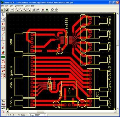
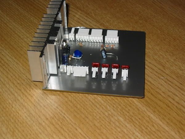
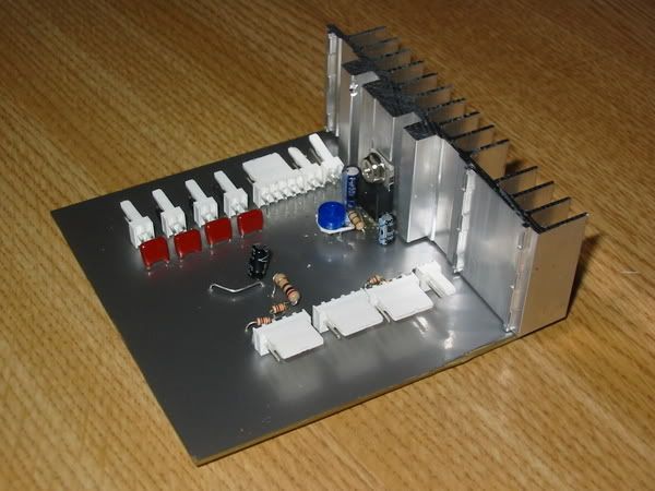
Here is the pcb I have come up with so far. It has three functions...
Thermometer
Monitor ID
signal pass through
Power regulator.
One it holds the maxim 1668 controller. Thats on the top right, of the board in the piccie... It will be top left when I have printed it on acetate and turned it over... To the right of it the thermometers will plug in. They will be made from transistors.
Next underneath is just a pass through for the psone screens signalling. Thats the lines running left to right (or is it right to left?) accross the board.
Under that and to the left is a 24LC21 eprom chip. This is going to be programmed with the correct settings to force the matrox GPU to speak to the psone screen. Will mean I wont have powerstrip running anymore.
To the right and below of the 24LC21 is a power regulating circuit that will give the 7.5v that the psone screen requires. It's using a the LM350T regulator and is designed to hand out up to 3a so it should be OK
My mental fragility was exposed as I desperately tried to work out what pins to connect, the pcb will be reversed on one plane when it finally prints. Ended up printing someone elses maxim based circuit onto acetate. This gave me a chance to try out the toner transfer method. I used a laser copying onto injet acetate. I tried a sheet full of circuits one at a time to try out various techniques. I got the best results heating it up real hot, then running it under cold water. The accuracy was good, but I want to try photoresist as well.
Got a 650 watt halogen OHP sitting. Might try that to see if its any good for exposing the PCB. I will hopefully try that tomorrow.
Oh and goof of the Day, went out to buy an injet cartridge. Needed a HP56, cam home with a 26 (24 squid). I knew which one I was after (I used to manage a pc shop, so I know many printers cartridges off by heart). I just plain read it wrong on the box. I only noticed it when I ripped the box open! :( No refund...
If anyone out there wants to critique my PCB design I will not be in the slightest bit offended. Its my first go at one. In particular, should I be filling in the ground plane? I gave it a try, but it didn't look as pretty... Not sure that a very scientific reason not to!.
Got a couple of more traces to tidy up, then I'm off to bed.
***Edit****
Forgot, I also modded my Matrox graphics card. Removed the VGA socket from the back of it. By using a saw to cut it in half while still on the card, I now have 15 header pins on the inside of the case. Will solder wires to them, which will plug in to the VGA signal inputs on this pcb. (Fingers crossed)
Update...
Had a very good day today.
Tried out the photoresist technique for making PCBs. I can recomend this technique for noobs to PCB manufacture.. Its so much easier to get a good print on the board than the toner method.
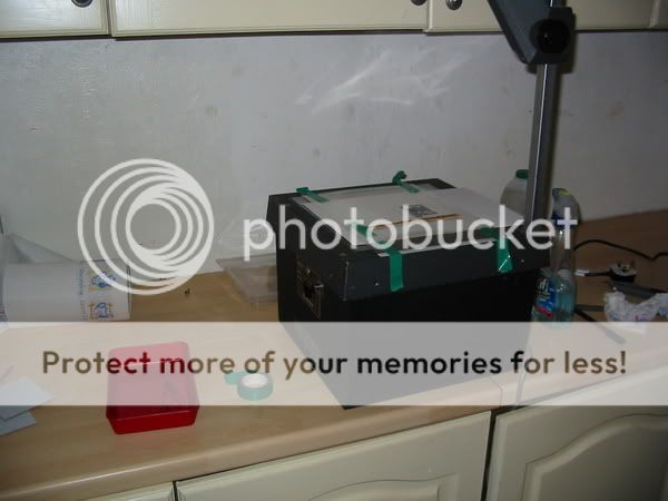
Here is the setup I used. I have an OHP which uses a 650w halogen lamp. This was going to be my method of exposure. First of all I inkjeted two copies of the circuit. I also added a test bar to the top of it. This had two functions. One to let me try a test strip, to determine my exposure time. Secondly it was to ensure that the two sheets of acetate were lined up correctly.
***Edit*** I should have mentioned that I removed the Fresnell lens before begining. The Fresnell would leave dark rings on the image. I have looked round the intermwebby, but noone else seems to use OHP's for this... I may have hit onto something here, it seemed obvious to me.
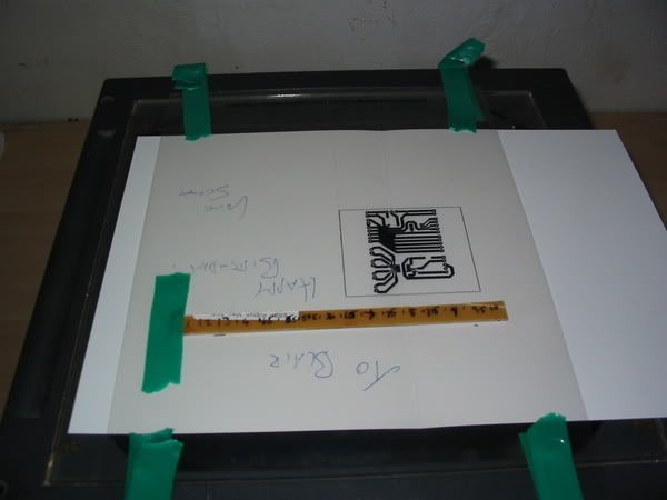
This photo is me getting ready to make a test exposure. The card under was supposed to be for cutting out the light. I intended to move it every 30 seconds to expose more of the board. When I turned the OHP on however light shone throught the card. I used some very thin alu sheet instead.
The rest is pretty boring, I just followed the instructions on the beginners kit I got from Maplins.
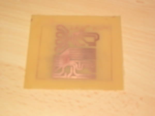
At the end I had a nice PCB
The camers still is rubbish for the closeups. There is a little pitting on 4 of the 0.5' tracks. This was cause i smudged the negative.
in this photo you can see the less shiny area where the pitting is worst. There is a hole in fact, but by good fortune it occured on the ground plane where I had widened the track.
Tested everything first by holding it against the lamp, then by multimeter. All is well.
Now for an admission... This was my second attempt. My first had scratches on it which cut several of the tracks. The mistake I made was when I was agitiating the developer with the plastic tweezers from the kit. I thought I would hurry it along. What I learned was that the photoresist layer is very fragile. Just brushing it with the tweezers is enough to damage it...
I didn't expect to get it right the first time so hey ho.
I'm in a quandry. Do I reprint my negs, and make a third attempt, or be happy I have a working PCB and move on. I'm thinking the latter, the imperfections are really not that noticable. I think I will drill it and use it. At least then if I mess up the drilling, I still have a spare photo board to make another.
Comments as always are welcome...
this is so cool
i never known you could make boards like that, the only method i know is painting the tracks(with paint) on a copper plated board, after the paint has dried you dip the board in some kind of acid, and you are left with only the copper under the paint, you then remove the paint and dril the holes........ but this so... so.......
This process is very similar to what you know already. The last stage I did was to bath the board in the acid. The only difference in the photo resist method is that you use boards that have a photo sensitive film.Quote:
Originally Posted by GT40_GearHead
The bath you see in the right of the pictures is the developer. The photo resist board has a film on it, when light activates it it changes the chemical composition. The developer strips off the changed part of the film to reveal the tracks. Then you bath it s before.
It really is a lot easier than I thought it was going to be. The closest thing I have done to it in the past is black and white film developing (when I did a photography course at school.)
Normally you would use UV light to activate the film, but a halogen bulb gives off some UV. The sheer brightness of the halogen makes up for the fact that only a small part of its spectrum is UV.
Something I forgot to mention in my previous post. Prior to exposing the board I removed the Fresnell lens from the OHP. If you dont do this, I imagine you will get rings on your board.
can you post a link or tell where i can find the kit ???
it would be great for my project
I got mine in my local elcetronics store. Maplins. Kemo is the brand name on the kit.
However you dont need to buy it as a kit. You can but the stuff seperately (I dare say it would be cheaper.)
The kit I used had...
A plastic tray
A pair of plastic tweezers (it has to be plastic, the etching solution is highly corrosive to metal)
A sachet of developer
A sachet of Etching Solution.
A selection of 3 PCB boards (one photoresist, one double sided, one single sided)
I bought an extra photoresist board, which I split in three. Two for PCB,s one as a test strip.
There are loads of tutorials on the web.. Google diy photoresist pcb. you will get instructions on how to do it. Some mention making your own photoresist layer. i dont see much point in that if your doing a one off. Pre-prepared photoresist boards dont cost much more than standard boards. Then you get a probably better board with less hassle.
Just one of many tutorials
great just great
made a quick bookmark, i will read it first thing in the morning
thx for the info, i might need to make my own photoresist layer, i live in romania, it in eastern europe, ex comunist country it was until 1989, so you can imagine that it has a lots a catching up to do
I dare say that you can get the stuff posted from one of the European mail order companies. I have been to a few ex soviet states (including Romania albiet only passed through on a train) and most things are available if you look in the right places.
no blood way, you actualy pased trough here!!!
what did you visited ?
I think the train stopped once . Cant remember where we stopped. Was round about 1991. I ended up in Bulgaria before running out of money. It was a railcard trip. I was young and mostly drunk throughout the trip!
ha haaa in '91 I had about 3 years :)))
Bulgaria is nice, i think they are starting to revive theyr economy
hope that after 2007 the EU would force some changes, the thing that gets me going about this is an easyer way for me to get to UK or france or maybe even get a job there.... but its a long way till then
Update...
I finished the pcb. Mostly without trouble, but I had an issue with the power regulator. First of all the good stuff.
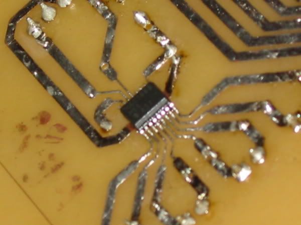
The temperature sensor worked straight away. Even though soldering the 5mm 16 pin soic looked terrifying, it was as easy, if not easier than the through board solders.
Here is the Maxim 1668 in all its glory! This is my favourite part, it looks so difficult to do, but it really isn't. From now on I'm doing surface mount stuff in all of my projects.
Tested it first, and the local sensor worked first time. I checked it with a medical thermometer, and the accuracy is better than the +/- 1c that maxim quote.
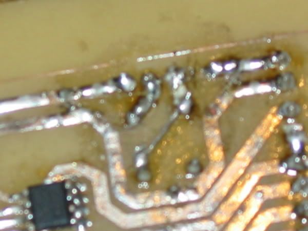
Here is the reverse side of the PCB. The 24LC21 chip is there as well. It worked first time as well. Though I haven't got it programmed yet to the right settings, it is accepting programming and is reading correctly by the matrox card.
You can see also that I tinned the copper traces with solder. Cleaned them fluxed them and then drew on a thin layer of solder. In real life you can't see the imperfections.
Now the gory bit. I tried the power regulator, but all was not well. It could be adjusted to the right voltage using an adj resistor. Then when I plugged the psone screen in, it just didn't light up... Bugger.
After posting for help on SPCR someone pointed out what was wrong. I had followed the manufacturers diagrams for the regulator. However the diagrams had the wrong pin assignation on them! How stupid is that? Then I had an issue. Do I start again? Do I keep the mostly working pcb and build a power regulator seperately?
Nope. I had another plan. I tore up a couple of tracks, inserted a couple of jump wires and lo and behold I had a working regulator. On the printed side (above) of the pcb it is a little messy, but on the side that will be visible, you can hardly tell the difference.
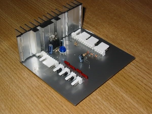
Then I attached a heatsink to the regulator. It was a heatsink from the first ps2 that I killed (technically sony slaughter... I didn't mean it your honour)
I also had in my cupboard some adhesive vinyl that I purchased in Hungary on an impulse (that will be usefull for something) purchase in March. This I used to coat the non tracked side of the pcb. It silvery, but non conductive. I think it adds a touch of class to the component side of the board, which will most likely be visible when I find a place for it. The result I am most pleased with... Check it out...
The other thing I am happy with is that I finally worked out how to use the camera... No more blurry closeups!
Now I have to come up with a creative way to mount it. That heatsink is live... Its only 7.5v so its not dangerous, but it will have to remain isolated from the chasis of the puter, I get sparks otherwise!
***Edit***
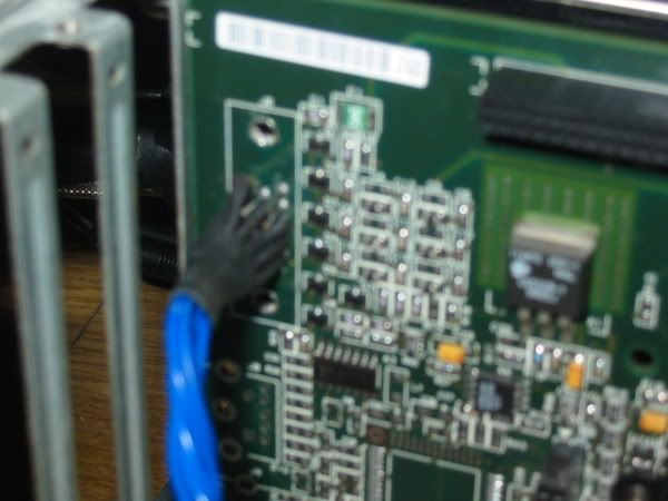
I completely forgot to say... I finished my mod on the matrox graphics card as well. As mentioned before I attacked the vga header with a hacksaw. What I was left with were 15 pins. I soldered some single core copper wire to these pins and at the other end added molex connectors to attach to my PCB. Here is the result...
This means all of the psone screens wiring is now held inside the case. I attached enough wire that I can hide it when it comes to final build time.
ZOMFG thats a big heatsink. i love the covering on the pcb. great job man.
Its not really that big a heatsink, the cards pcb is 8x9cm the heatsink is 9x2x3cm.. Its bigger perhaps than I need. (it gets hot though) but I err'd on the side of caution cause its going to be in a passive system.
The vinyl I am pleased with. Haveing looked in the photos it looked like it had a couple of tears in it. Have checked and to much relief, that turned out to be a couple of pcb shavings.
l
woooow great job dude, it looks so damn pro!
the vinyl ads a lot to the whole thing
Well this update has been a while coming....
So what have I been up to?
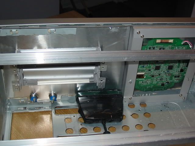
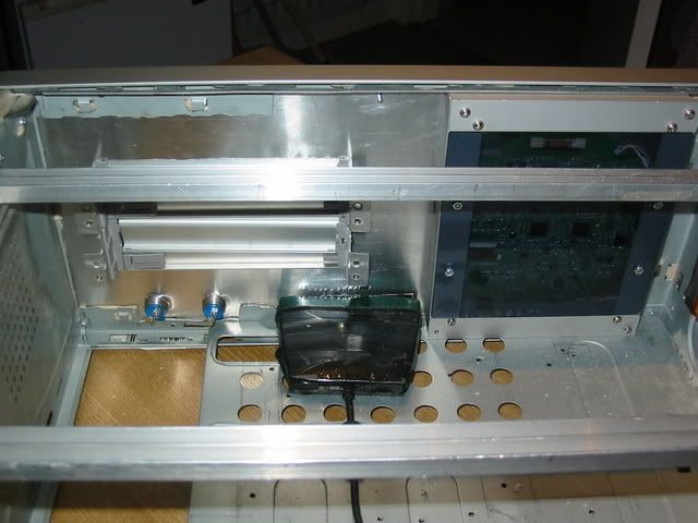
Well. I built a mount for the psone screen. This I made out of alu L brackets. Finally got to use my drill press in anger... What a usefull tool it is.
Basicly I made a rectangular box. Then using four bolts through the screens mounting points I had an adjustable (for depth) mount.
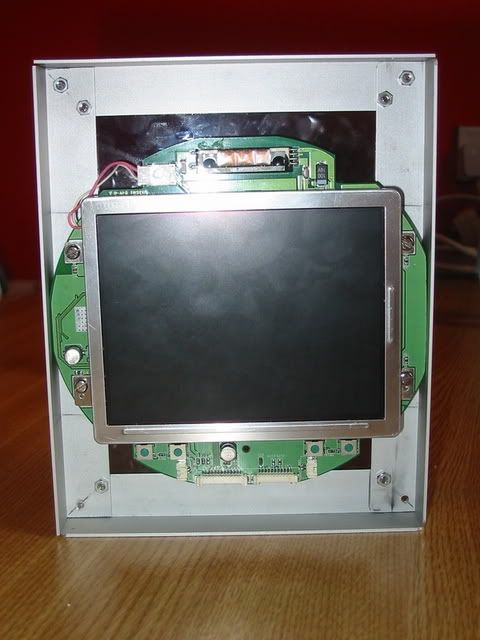
Here you can see the psone mounted (ooh err).
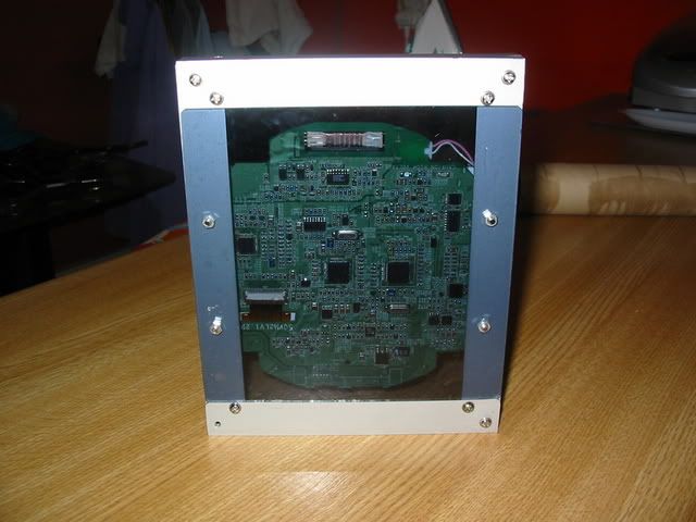
And one from behind (double ooh err!)
When I fired it up, nothing happened... I had damaged the cables at the molex end going into my homemade pcb. The problem (I found after spending an hour with a multimeter) is that the psone screens cables are very fine. This was a relief, as to get the right clearances I filed off about a centemetre of the screens pcb. On the right of the pcb is a lot of ground plane, this is what I removed. I have a plan to make a more durable connection which is yet to be executed. I did though get it working.
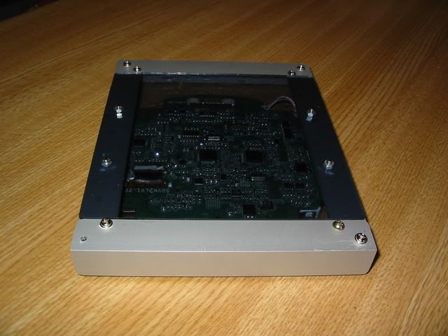
When it was lit up I noticed something that had eluded me before. The backlight of the screen shines through the pcb highlighting the gaps between the tracks. This i thought had to be exploited. So I made a cover for the back. i used 2mm thick perpex then covered it in a smoke tint film (the kind you get for car windows).
When I get the power to this, I think it will look pretty damn good.
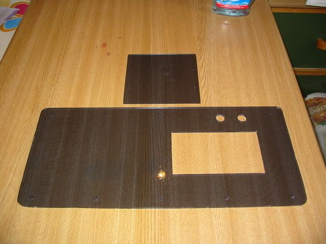
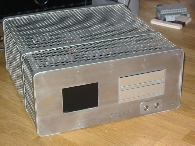
Next on the things to do list was a front panel. This is made of a very thin sheet of alu, then a sheet of perspex in front of it.
There was a lot of cutting and shaping to do to both layers. On the perspex there is a hole cut for the drive bay covers (lian li) plus two stainless steel buttons which will be the power buttons for the pc and the playstation.
I also drilled and counter sunk some screw holes top and bottom to hold the facia onto the case. I had considered glueing, but the countersunk screws I think look cool. It would perhaps have been a bit bland otherwise.
On the alu I did the same plus cut a hole for the psone screen and the remote sensor. Here is the result....
The scratches are on the alu sheet behind. There are still some bubbles on the tint, but I am hoping that they will disapear as it dries out.
I am pretty pleased with the result. There is a whole lot more to do, but I think that the front panel is getting to the point where you can imagine how the finished case is going to look.
The alu will be spray painted black. This should make the psone screen and the IR sensor disapear behind the smoked perspex.
On the to do list now.
1. A side panel needs to be manufactured with the PS2 inputs, Usb ports and two rotary switches (with alu dials of course) which will switch the usb (between the PC and PS2) and switch the lights and psone screen on and off.
2. A base needs to be made. i have a set of sorbothane feet already. Some of the base will be meshed.
3. I have a sheet of perspex mostly cut to sit on the mobo tray where it is exposed. i will cover this in some more of the silver sticky backed plastic. The pcb will mount to this.
4. I will have to redo the ps2 controller extensions to take into account the new location of the psone.
5. I have to build a new mount for the ps2
6. I still have some tidying to do for the case lid, including screwing it all together. I plan to use countersunk screws in the alu bands. I also have to put a final strip in on the front at the bottom.
Ideas are still welcome even at this late stage?
Amazing. I'm just blown away. I've been following since day one, keep up the good work.
lol Mean Lean Grilling Machine. Nice.
This mod kicks some serious ass. Great work with the circuitry, i'm rubbish at Soldering. I'm hoping to improve over time with practice.
Well done with those tiny little pins though, how you managed that, i'll never know.
-Dave
Soldering those little suface mount chips is not that hard to do... This was my very first attempt at them. Its one of those jobs that looks way harder than it is.
Best advice I can give to anyone considering it is to check online for video tutorials for surface mount components... There are loads of them out there.
The key points to this kind of soldering.
1...clean the contacts first with a pcb solvent. I think you might get away without doing this, but a pen is a few quid, and it is very usefull for cleaning up after.
2...Use a flux pen to apply liquid flux to the solder contacts. This bit is essential
3...Then place your chip. (the guides suggest a magnifying glass on the tools list. I didn't need this) I found the flux was slightly tacky making this easier
4...Then holding the chip in place with tweezers or fine pliars, dry solder the chip in place. Basicly press down on one of the outside pins and it sticks to the board. Then dry solder the diagonally opposite pin. This bit makes it a whole lot easier.. Again essential IMO
5...Then place the wire of solder accross the base of all the pins on one side.
6...Starting at the top of the leg of the chip mover your iron downwards into the solder. As if by magic (and this is where the flux makes a difference) the solder melts and sticks only to the board and the chip contacts. Accuracy is not that important, you can do several pins at the same time.
7...If you get any bridged contacts, drawing the iron down again, then along the pcb trace wicks the excess solder away and the gap is formed. A little more flux may be required if your origional application is no longer liquid.
8... Finally use your solvent pen to clean the now brown and goey flux from the pcb.
9... Stand back and marvel at your work. Better still stick the pcb directly under the nose of a family member and demand that they hail you as a deity.
Thanks to all that have given such kind and supportive posts!:)
and...never run your soldering iron under the tap to cool it down, because the rapid temperature change will form limescale (or something hard and unsavoury) thats a pain to get off, and will ruin your iron (cos the solder will flow along it, and touch the board).
Good advice Chedabob.
Also pick it up by the handle when its hot! I learned that one through experiance I am afraid!:eek:
holy **** that is well nice man!
How long overdue is this update then???
I have not been lazy though I have made some progress..
First of all the bad news.
The window tint did not take on the perspex. I dont know why, but I got too many bubbles in between the tint and the glex. This was frustrating to say the least.
So I was left with 3 options...
- Try again with the tint
- buy some proper smoked perspex
- come up with another idea
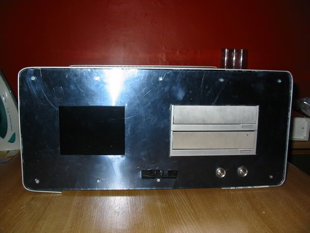
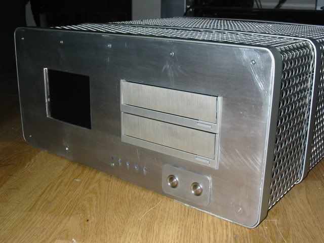
I tried to source some smoked sheet perspex, but was not having much luck, so I thought I would give the third option a go. I managed to source 3mm thick sheet alu locally so I thought that I would give it a go...
What do you think.
Of note in the design is that I made a small panel for the power switches. It is made from a sheet of thin perspex sandwiched between the main 3mm sheet and a much thinner sheet (1mm at most) of alu. The power buttons hold the panel together. I have been experimenting with shining blue leds through perspex rods to backlight the panel. I get a nice sort of glow from behind it. I should really be honest, this was not my origional plan, but I messed up with the drilling of the holes in the 3mm sheet. My 16mm drill bit chewed up the sheet leaving a rough edge that I just couldn't fix. The panel masks this. I have plans to try making a couple of panel designs to see which I prefer.. I'll be taking votes.
You can also see in the photo how I tackled the IR sensor. I used my drill press to cut a set of 5 4mm holes in the pannel. I then forced through some perspex rod, trimmed it and then sanded it down to flush. The final stage will see the whole front facia polished to either an even brushed alu or more likely a mirror finish. The pespex in the sensors by the way is not that light looking in real fife. Its very dark in fact but the flash lit it up.
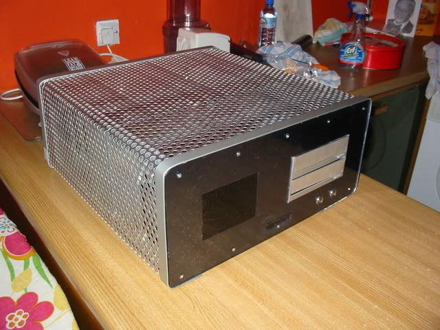
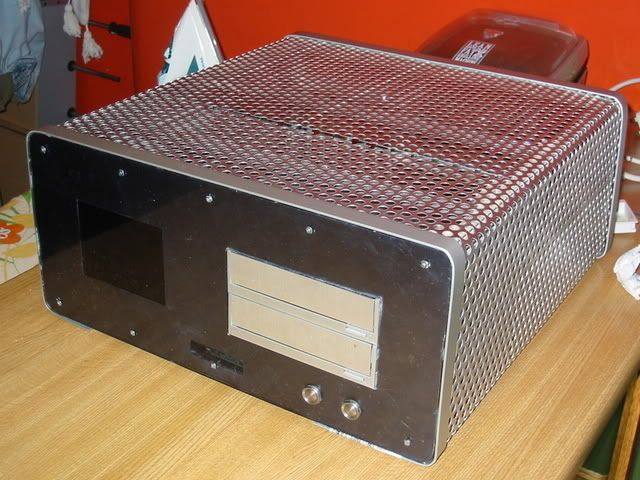
What you cant see in the pictures (cause I forgot to take a snap) is that I have removed even more of the steel in the chassis. I added a couple of alu w shaped rod in first then jigsawed out the remaining side panels. This is of course to add more ventilation.
I had origionally intended to keep these in to mute the sound of the HD. But the enclosure has been so successful, I have no need for this.
I have a plan sorted out for the back of the unit now as well... More Alu. I have enough 3mm sheet left to make a cosmetic plate to tidy the back up and also to put a polished alu sheet in to the exposed floor of the case.
I also made a first attempt at the side panel for the case, but you will have to wait on that one, I think I will be revisiing it again
In the meanwhile, does the alu sheet get a vote of confidence or should I try and find some of that elusive black perspex?
personally, i'm a huge fan of the industrial look, so i love the way that case looks right now.
if you stick with the aluminum, i'd vote to go for the brushed look over the mirror. but then, it ain't my mod either :P
one more vote for the brushed aluminium,
i just cant resist it!
and i must ad that you did a wonderful job so far
www.tapplastics.com
they have some samll sections you can order...thought they may be too small for what you need.....but their pricees are low
i plan on ordering from them when i need some more
I think that they are US based, thanks for the link, but I am a few thousand miles off the beaten track. I see they do international orders, but they mention mail for price on these and the buyer pays on transit for damaged goods both ways.
It would be more a UK or European supplier that I would be looking for.. Thanks though for looking that out for me.. Do I take that as a vote for the perspex then?
As for the other comments, thankyou. The brushed is probably the more subtle effect. I am swayed a bit by the shiny, though I am not sure for definate. Would welcome any opinions
my votes for brushed aluminum...looks better with that specific case design :up:
oops...yeah sorry....forgot youre across the pond:dead:
Very PowerMac-like. I dig it.
I see what you mean, The mac was not my inspiration though, this ones more along the lines of "Neccessity is the mother of invention" in the design process.Quote:
Originally Posted by a.Bird
Legal Disclaimer...Any resemblance to other PC's real or imaginary is purely coincidental.
Lmao, "real or imaginary". There are no legalities when it comes to imagination, damnit!
I've been watching this project for some time now and it looks like you know a lot about PS2's so mabye you could help me. I got a PS2 from my auntie (she had been having trouble with it), she had it repared once and it broke again, it was the fuse. I replaced the fuse, turned it on and it blew again. My uncle said he had tried this but every fuse he put in blew. The fuse is a standard 250V fuse and I was wondering if this wasnt enough? I also thought it might be the AC power adapter. any ideas. If I can't fix it EB games take broken consoles anyway.
is it a fuse inside your ps2? either way you may just need a new psu for it.
just do some research on your model of ps2 you have and which psus go with it. otherwise you could pull it out and look for a model number on the power supply itself.
Well it was one of the first ones when it was bout $700 AUS. My auntie just bough a new one lol.
Looking great!
I preferred the smoked plexy idea myself. - it's a little too plain when its all aluminium..
If you could use smoked plexy and stealth the drives it would make it look 400 times better in my opinion but it looks great as it is and what realy matters is what YOU like :)
H
@The boy 4rm oz
Hi. Sorry I took a couple of days to spot your posts
Regarding the playstation 1. I certainly wouldn’t consider myself an authority on them yet, but I have learned a bit.
The fact that it is blowing a fuse when you plug it in would lead me to suspect that it is indeed your power supply that is buggered. I would imagine that if you open the thing you will find a blown capacitor on the power supply board. If you are opening it, a small word of caution. The capacitors on the power supply are capable of holding a charge, so be carefull what you touch. The caps on these supplies are not too large, so I doubt it would injure you too badly if you got a jolt, but it wouldn’t be pleasant! You can test to see if the power supply is causing the fuse to blow by removing it from the playstation and then powering it. If the fuse blows then its buggered.
In your playstation there will be three PCBs. One will be the power supply itself, easy to spot as it will have a few large components on it and the chord from the rear switch will enter it. It’s the easiest to get to. When you remove the bottom part of the case, it will be the first thing you see. Its held on with four screws. And you will be looking at the underside of it. Remove it carefully if you have had power to the unit recently. Inspect the components on the top side. My guess is you will spot a burst cap. If you do, then you know that it is the power supply that is burst, if not power it up and see if its broken or not. Do this with extreme caution. Mains electricity is dangerous and can kill. Then you have some choices….
1. Buy a power supply from an online parts store. But if yours is one of the origionals this might be both difficult to track down and more expensive than the machine merits. The playstations have been through a few revisions (10 on the old style case), and the size and placement of components vary between revisions.
2. If its a blown cap you could desolder it and replace it with a cap of the same value.
2. Modify an external power supply to attach it to the old board. This is the route I would take, its probably cheaper. I seem to remember the ps2 is rated at about 3A, so you would have to make sure the supply you used was rated high enough. On your playstation there are 4 pins that carry power to the electronics. They are in the same dimensions as a molex plug uses, but don’t be fooled into thinking they are wireed the same. 2 carry 12v and 2 carry the common ground. You have to identify which is which. This I did by measuring a working power supply with a multimeter, but you can also search t’internet to get the right ones. Then you can either snip the external power supplies 12v plug and hard wire it to the pins or you could buy a socket and wire that up to give yourself a plug in external power supply. This is similar to what I have done for this project though I have used the 12v line from my PC power supply.
If that doesn’t work then you have to look to the surface mount fuses that are on the playstation itself. A t’internet search will help you find diagrams to identify them. A multimeter is essential for this job as you will have to check them to see if any are blown. If they are you can either replace them (if your good with a soldering iron or bridge them. I use conductive ink to do this, simply painting over the top of them. It’s a quick and durty way of working, but on an old playstation who cares?
@onlegout. I know what you mean about the alu being plain in comparison. However I have a plan to combat it. The screen for a start will hopefully add interest to the front when I get it wired in, I have also created a lighting effect for the pannel around the power switches. Hopefully this will add sufficient interest to the front pannel to get over the sameness with the sides and top. Time will tell :0)
I pulled the whole PS2 appart and studied everything closely, I have seen blown capacitors on PC motherboards so I know what I am looking for, it was the first this I looked for after finding the fuse. I disn't notice anything out of the ordinary so I just put it back together and fired it up, it worked for a few seconds before i heard a loud pop and it shut down. I can't really be bothered fixing it if I gotta get a new PSU or stuff around with an ATX PSU. I would just get a better trade in if it was working lol.
Thanks for all your help, I migh try some of your ideas and get back to you.