Haha your right, does look like it has been submerged. Looks awesome.

Printable View
Haha your right, does look like it has been submerged. Looks awesome.
Update: LCD Screen
Still waiting on some more acrylic before I can begin the side panel, which is a little frustrating, however .....
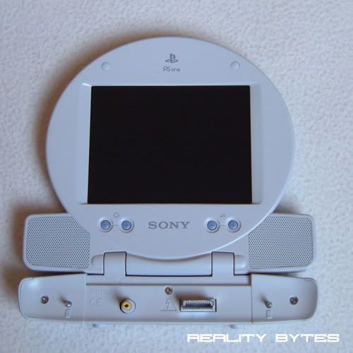
Today my PS1 LCD screen arrived, I picked it up on Ebay second hand so it cost next to nothing, which is good as I have never modded on of them before. I have read a few tutorials on various sites and along with some help from you guys I am confident I can get it to work.
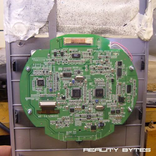
So first off here is a picture of it straight out the box:
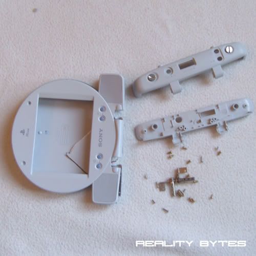
Obviously I am not going to mount it in its casing. I need to get the LCD and its circuit board out, time to take it apart.
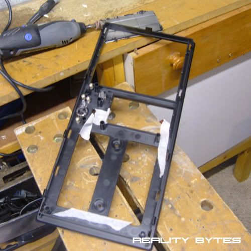
A few screws, a little frustration and some snapped plastic later:
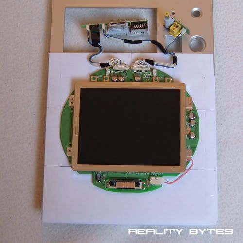
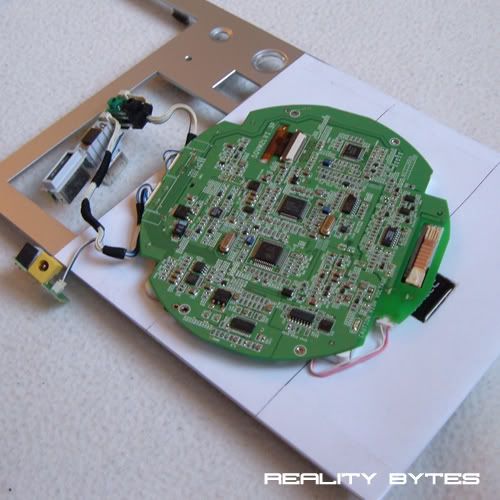
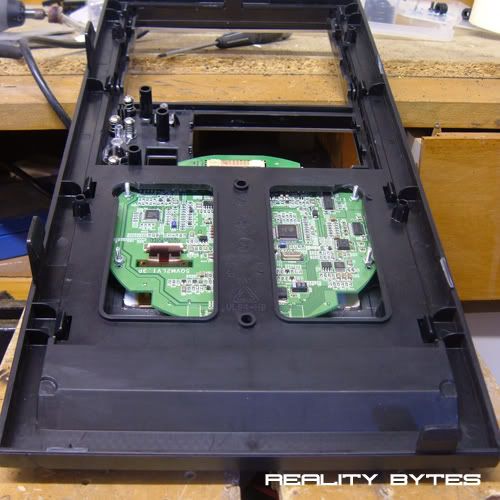
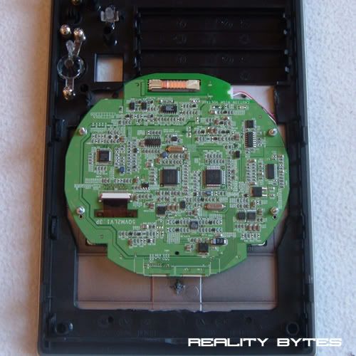
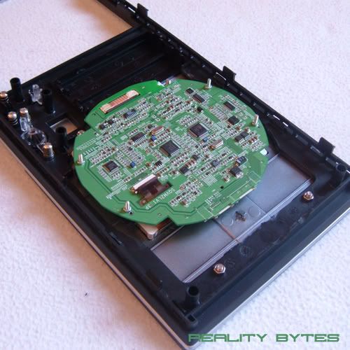
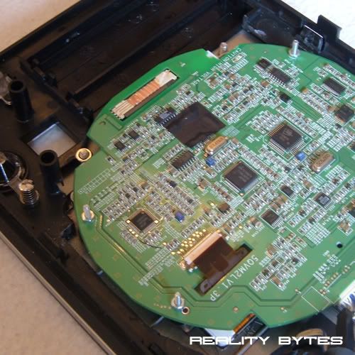
Here is the screen and circuit board removed from the case:
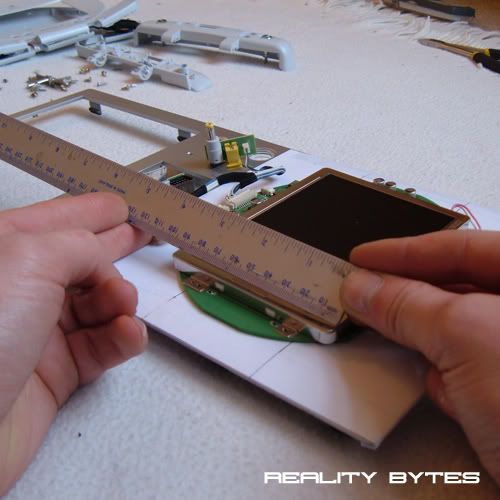
Now to take some measurements of the screen and surround in order to mod the area it will be mounted:
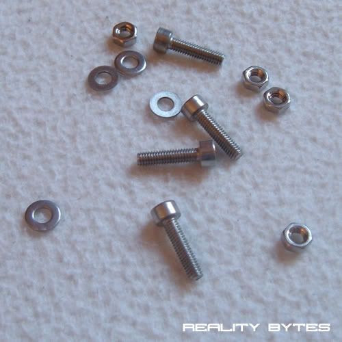
I was running a little low on fixings so also brought some more nuts, bolts, washers and threaded rod. All M4 in size and all bolts are the socket cap type that I have tried use throughout the case:
I am going to mount the screen in the front panel of the case, below the 3.5" bay covers.
A few pages back I said I was unhappy with the front panel as it was too 'stock' and TBH just looked like a run of the mill PC face. I think having the screen mounted in it, to use as a system monitor or just to have visualizations playing, will add that much needed eye candy. Also the whole front panel will be covered with 3mm smoked black acrylic, but that's for another day.
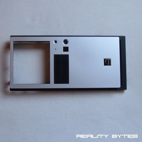
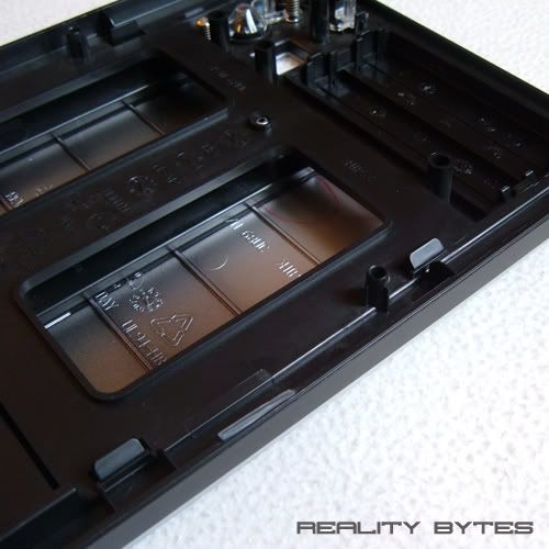
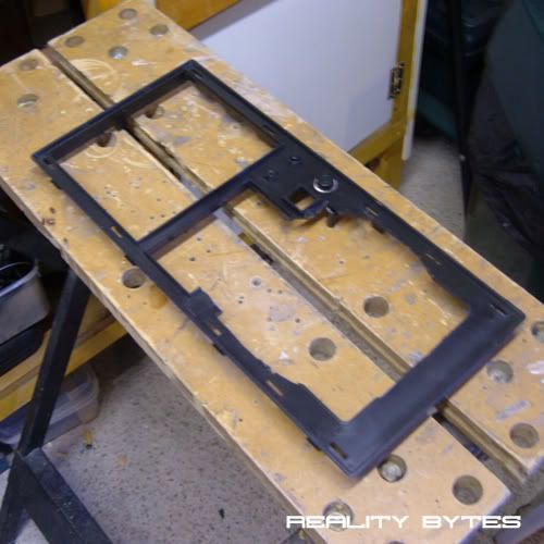
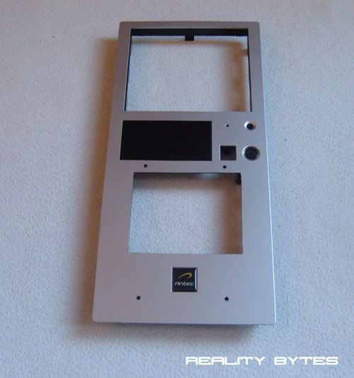
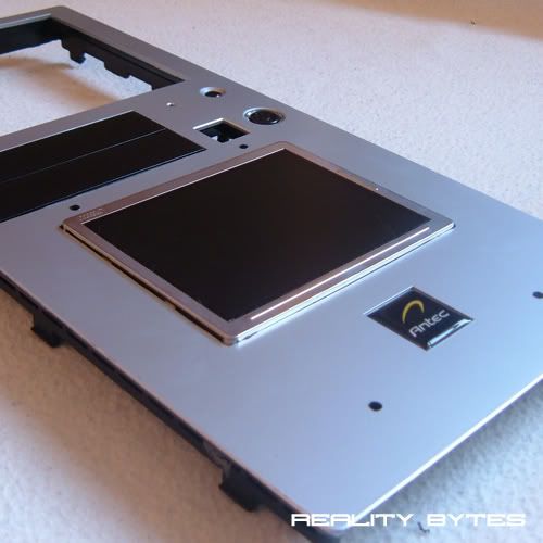
Here is the front panel removed from the case:
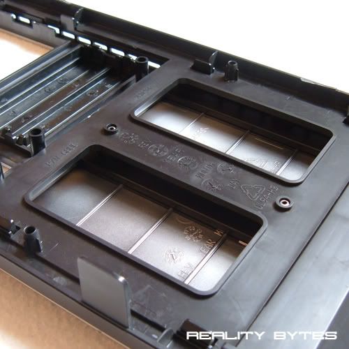
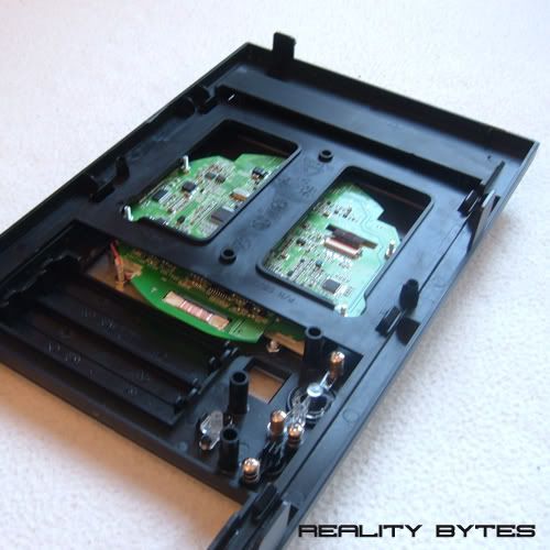
The panel is in three parts (all ABS Plastic), this is ideal as it gives plenty of space between them to house the LCD circuit board.
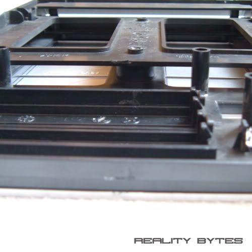
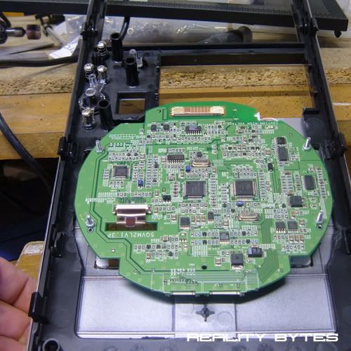
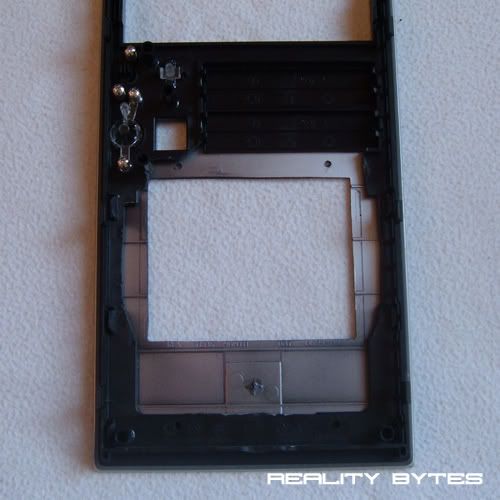
Here are a couple of pictures of that space I have to work in:
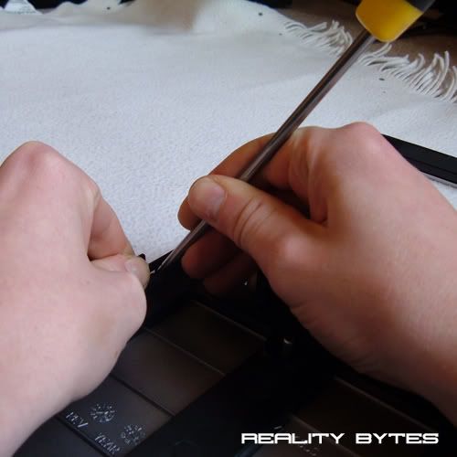
So lets get those three panels separated. They are all (rather cheaply) held together with small plastic tabs, as you can see below:
The tabs are quite fragile so I gently prized them apart with a flat head screw driver:
Now its the same deal to get the inner panel detached from the front faceplate:
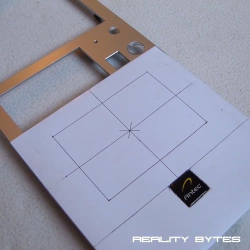
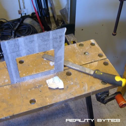
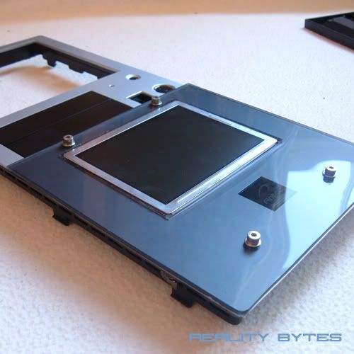
Now that the silver front faceplate is removed I can mark out measurements for the area I need to remove in order for the screen to show through:
Initially I marked out the area between the bottom of the 3.5" drive bays and the top of the case badge, then measured the area to find the centre point:
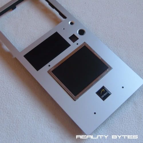
The area of the screen I need to be visible through the front panel is 115mm x 80mm (5" screen) so using the centre point as a starting point I marked this out on the front panel:
That's it for now, this weekend I will be able to get down the garage and start cutting the front panel to mount the screen and also cut the acrylic to go on the front and then it will be time to try and wire it all up ..... :twisted:
Thanks For Reading
Looks good. What are you going to display at it?
I will most likely use it for system monitoring whilst gaming etc using a Samurize config. Then the rest of the time have visualizations playing along to my music.
This is one killer looking mod man. Very clean and very cool. +rep dude.
OHHH pretty lol. Can't wait to see this mounted mate.
Update: LCD Screen - Part 2
Hello everyone,
Pleased to say I had a good day of modding today, I managed to spend some time down the garage and got quite alot of work done on the LCD / Front panel.
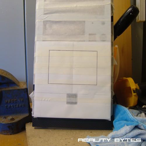
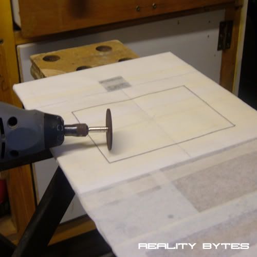
Lets get started! Masked up the front panel for cutting:
Out comes the dremel:
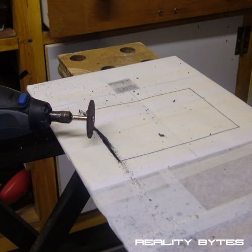
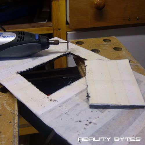
Cutout for the screen:
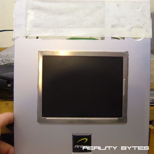
Then a quick test fit. I was going to hide the silver surround but decided to have it exposed as I quite liked having a bit of shine:
And from the back:
Now to mark up the second panel for cutting to allow the screen to fit in:
Cuts made:
Another test fit:
Then the third panel:
Test fit:
Next I masked up some black smoked acrylic to make a surround:
Lots of smoothing and sanding. I used 200, 600, 1500 grit sand paper to polish up the edges:
With all the cutting and sanding done it was time to get some lunch and get back indoors out of the freezing cold garage and fix everything together.
First and second panel joined:
To raise the screen away from the circuit board for a smoother fit I made some spacers from the parts below:
Then fitted to the screen:
Allowing the screen to mount through the front panel:
Now for the acrylic surround:
I fixed this through the front panel with M4 nuts and bolts:
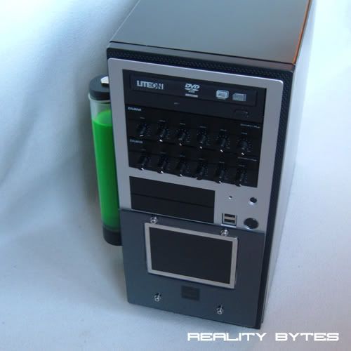
And the finished product fitted to the case:
I am very happy with how todays work went. I still have got to fit some more acrylic to the front panel to finish it off but I hope you will agree, it now looks alot better than it did before.
Next is the wiring, not looking forward to that in all honesty but its got to be done.
As always thanks for reading, let me know what you think.
It really fits well with the overal look of the case. Good job! Are you going to make it work on your VGA port or will you just put in an S-video?
Very clean looking facade, looks like a high quality stereo component. Great work!
Thanks Maleficus, and thanks for the +repQuote:
Originally Posted by .Maleficus.
Thanks TEAMIKKE, I am going to wire in a VGA connection, should get a better picture that way than with S-video. I have got the pin-out diagrams, just need to get a new tip for my soldering iron now as its a very small area to work on.Quote:
Originally Posted by TEAMIKKE
Thanks jbdnsn, much appreciated.Quote:
Originally Posted by jdbnsn
Looks great mate, can't wait to see how you finish the rest of the front. +rep
Thanks The boy 4rm ozQuote:
Originally Posted by The boy 4rm oz
No problem mate. I thought this mod looked great in your first post but it just keeps getting beyyer and better, keep it up.
You landed front page!
Wow!!!! Thanks.
With all the amazing worklogs going on at the moment I am chuffed to bits mine has made it to front page.
Better get an update done .....
Congratz on the front page man, a huge achievement.
Expected nothing else ;)
Update: Loose Ends
I should have all the components I need to wire the LCD screen up to the PSU and graphics card by tomorrow, so I wanted to tie up some loose ends today leaving me free to concentrate on getting the screen up and running.
One problem I was having with the screen was that it was not as secure in its mounting as I wanted it to be. The front panel did hold it in place enough to stop it from moving around, but if the screen where to get touched or knocked it would move slightly backwards into the front panel.
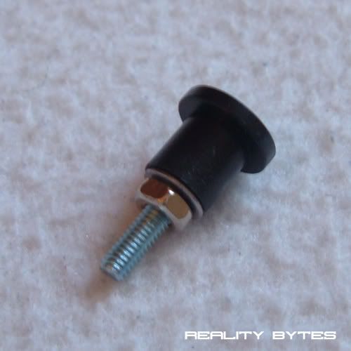
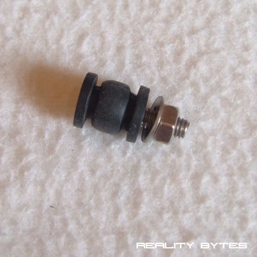
I didn't want to use a glue gun nor to have anymore visible bolts on the front panel. So I came up with the idea of making a rubber 'foot' that would press against the circuit board of the screen and hold it in place.
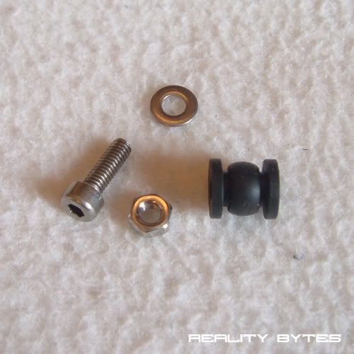
The parts used:
How they fit together:
Even though the metal bolt is covered by the rubber grommet I applied some insulation tape to the area it would press against:
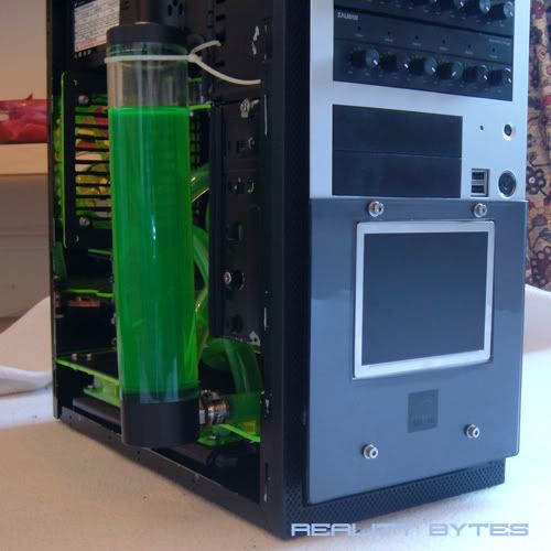
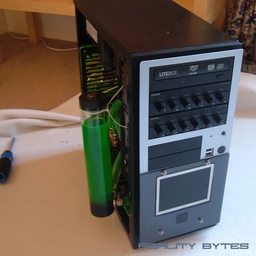
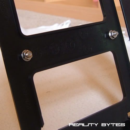
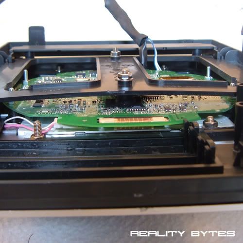
Now the bolts applied to the front panel:
Now from the picture below with everything back together you can see that the new bolts press firmly against the back of the screen holding it in place:
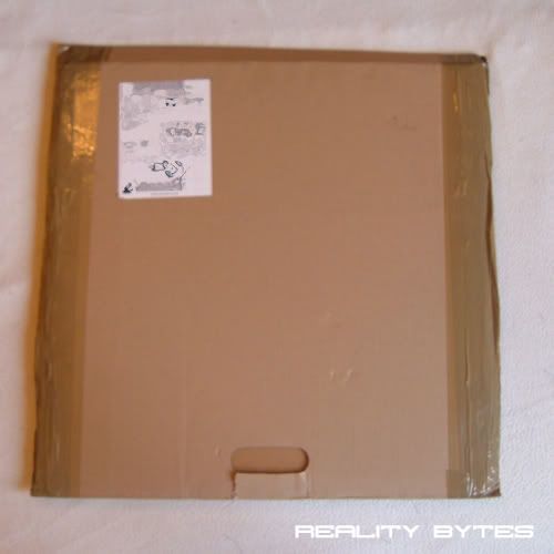
The next task I was part way through was the inner side panel I made a template for a few pages back. The only thing holding me back was waiting for some black perspex to be delivered. However just as I sat down to lunch it turned up:
2 sheets of black acrylic - 500mm x 500mm x 3mm
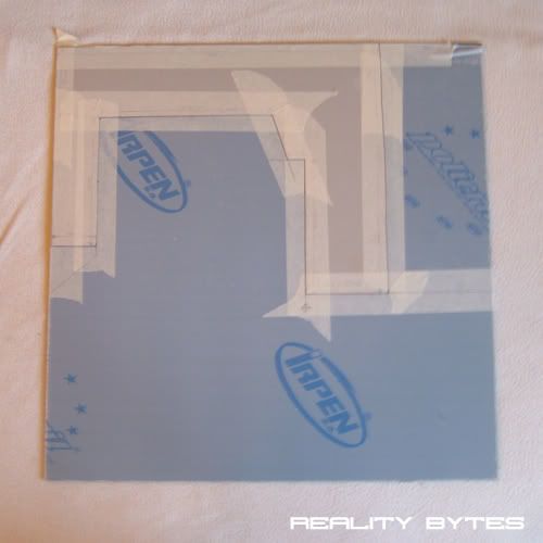
So with lunch now becoming 'take-away' I marked out the template on the sheet:
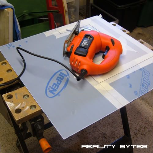
Then off to the cold garage to start the cutting:
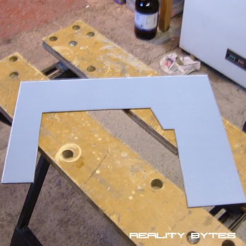
The cut went really well and only took about 15 minutes, however sanding down of the edges took much longer, well worth it for the nice smooth polished up edges though. Again I used 200, 600, 1500 grit sand paper to get the desired result:
Back in from the garage I removed the protective covers from the acrylic ready to test fit it in the case. The acrylic is a very dark black and has a very glossy, near mirror finish which looks nice against the matt black of the case:
Finally here it is mounted in the case. I decided to stick with the original shape of the cutout because I didn't want to over-complicate the lines nor the overall shape.
Once I start on the outer-panel I will be able to secure the reservoir to the inner panel which will also hold the panel to the case, but for now its just the tight fit holding it in place:
And one last picture to show the glossy mirror shine:
That's it for today, should have another update tomorrow with the wiring for the LCD screen.
Thanks, as always, for reading. Looking forward to some feedback.
Very clean.
I hate it, you've made me realise how messy my loop really is :( :p
+rep for the sweet work and tidyness.
Even better than it already was:up:
I agree, can't wait for that side panel to be completed.Quote:
Originally Posted by TEAMIKKE
First off I wanted to add my +rep to everyone else's...this is a beautiful mod...like the others said, clean, simple and smooth. It really is an inspiring mod man, great work! Secondly, where did you find the pin-out diagrams for that screen? Thanks!!Quote:
Originally Posted by Xperiment
Thanks TEAMIKKEQuote:
Originally Posted by TEAMIKKE
Thanks Scotty, and thanks for the +repQuote:
Originally Posted by Scotty
Thanks dfigravity, I got the pinout diagram HereQuote:
Originally Posted by dfigravity
Thanks The boy 4rm oz.Quote:
Originally Posted by The boy 4rm oz
Update: LCD Screen
Hey Guys,
Only a small update I'm afraid, Maplins seem to think 24hour delivery means "will take over a week" :eek:. So I am still waiting on parts to get this screen up and running.
I have made a start on the wiring however.
Here is the adapter that came with the screen for the video/sound output:
As you can see from the picture its a very small area to work in, and knowing the limits of my soldering skills I decided to mod the wires that connect to the adapter instead of soldering wires onto it.
Here is the connector to mod:
There are 10 wires in total, I only need 6 of them to connect via VGA. So I cut into these and lengthened them with some thin wire so they will run from the screen to the output on my graphics card. Each wire is numbered to correspond to the pin on the VGA connector:
Then this end will connect to the screen:
Now here are the wires connected to the screen:
And finally here they are braided:
I also made a quick connector for the screen power. Just a molex connector running to a toggle switch. This will then connect to a small circuit to drop the 12v to 7.5v.
Hopefully Maplins will pull their finger out over the next few days so I can connect the power to the screen and wire up the VGA connector. Then we should have a working LCD.
Thanks For Reading :)
OOOHH update lol. I hate waiting for parts. Great progress.
Update: LCD Screen
Some good news, my order from Maplins finally turned up today, However when I opened it and started checking off all the bits and pieces I noticed they had not included the last page of items :?
The parts they left off aren't urgent but its still very frustrating, and now I have been told they will be with me in 3-5days !?!?!?! pfff
But anyway the modding must go on. The only missing part that will cause a bit a problem is the stripboard, so for now please enjoy some Ghetto electronics ...... :banana::banana:
Powering the screen: Ghetto Testing
A big thanks to 'xmastree' for coming up with the circuit diagram to allow me to reduce the standard 12v supply from the PSU to the needed 7.5v for the screen. Original Thread
This is what I will be working to:
I will be testing this circuit on two outputs, the first of which is a set of two 12" cathode tubes. The thinking behind this being that they were the highest wattage 12v item I had to hand.
Below you can see the 'Ghetto' arrangement used to test:
So after connecting everything and switching it on I used a multimeter to measure the voltage being supplied to the cathodes (from the outputs on the circuit diagram).
This gave a result of 7.88v.
A good result and well within the range the screen can cope with.
Next I used a simple 120mm fan, again connected Ghetto stylee:
The voltage reading for this test seemed to be less stable, moving from 6.90v upto 7.65v. I left it running for around 3 minutes and it did level out at around 7.30v, again a perfect supply for the screen.
I am very happy with the results and quite confident that the circuit works the way it is meant to. However not being that knowledgeable of all things electronics I wont connect it to the screen just yet, I will run a few more tests first.
If anyone can see anything I have done wrong here, please point it out to me, you may just save my screen :bunny:
I have done a little video of the 2 tests hoping this will highlight any problems:
I now have my 15 way D-Sub connector (VGA) so tonight will be able to solder this to the video inputs on the screen, an update on this to follow.
But that's it for now, as always thanks for reading :)
Getting closer and closer to seeing this screen up and running.
wow this looks really really good. I wanna use that ps1 screen in my car for my car pc if i ever have money to that. +rep for an awesome mod :)
Looking good so far. If the power seems unstable, it might be an idea to put a capacitor across the output to smooth things a little. Got any dead electronics lying around?
I didn't realize it but imagispire actually made two custom headers for you so I added the other one to the first post. You can pic one and remove the other or use both if you want.
Hey man, I was just wondering if those fans you are using were AC Ryan Blackfires? If so do you find them loud? They are rated at almost 29dba and just thought I may ask.
A while ago I did strip a DVD player and an old motherboard of all its caps and other bits before I threw it away. So will try out a few different caps to see what happens.Quote:
Originally Posted by xmastree
However, It seems transistors don't like short circuits lol
Will have to pop over to maplins again, cant be doing with their delivery again.
Yes dude, they are AC Ryan Blackfires. As for the noise, it depends where you mount them, what voltage you run them at etc.Quote:
Originally Posted by The boy 4rm oz
I find that at 5v they are silent, of if they have nothing directly touching them at 12v again silent.
But if you run them on a rad at 12v they can be a tad noisy. I tend to run all mine at 5v-7v.
Good fans though, would recommend them.
Well I will be mounting my radiator like you have, same fan and radiator orientation. I will also have silicon washes on the fans and radiator to try and reduce noise. My motherboard will be powering the fans so I guess that will regulate voltage and noise depending on the heat of the system.
AC ryan fans are noisy but they move a lot of air! You have to make choises or let them run @ 5V indeed.
OT:
Dude, I need to know what settings you are using on your camera. I have the same one, and can't get mine to come out as good as yours.
Back on topic:
The project is looking great man. Keep up the good work.
I use macro mode and auto focus on the camera itself. Quality is set to 4MF. I use a tripod to keep it steady.Quote:
Originally Posted by SgtM
Self timer helps for the closeup shots to keep the picture sharp. Also try half pressing the 'shoot' button until a small yellow box comes on the screen, wait a couple of seconds then fully press. I think this increases the shutter speed for a sharper image.
I also take about 3-10 pictures of the same thing then pick the best one.
As for editing the picture once taken, I move to photoshop, select a square area and crop, then reduce it to 500x500 pixels, this seems to improve sharpness a little more.
Hope that helps.
Thanks, slow but steady at the moment.Quote:
Originally Posted by SgtM
Update: LCD Screen VGA Connection
I really want to get this screen up and running now, what with waiting on deliveries and blowing up transistors it just seems to be taking forever to make progress on it.
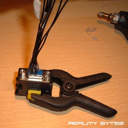
So today I wired up the video inputs to a VGA socket. The plan was to do this using a bare 15 pin D-Sub plug which would then plug into a VGA -> DVI adapter.
When I grabbed the adapter I noticed how easy it would be to plug the wires straight into it rather than solder them to the VGA plug. So I cut some lengths of solid core black wire and slotted them into the adapter:
Then labeled each one so I knew which wire was from which pin:
Used a hot glue gun to keep them in place:
And used heatshrink to cover up the wires:
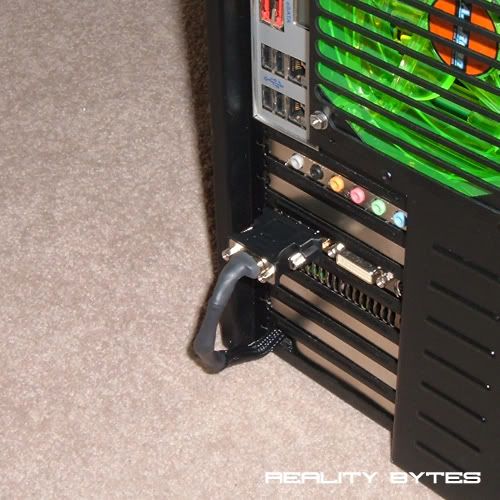
Lastly I connected up the wires to the loom already fitted to the screens inputs and ran it through the case, hidden behind the radiator, before coming through the rear expansion slots and into the graphics card outputs:
Now that this is done all I need is a new transistor and it will, at last, be ready to switch on.
Ouch... I saw the pic before I read the words, and thought that had happened when you plugged it in...Quote:
Originally Posted by Xperiment
What are you using for a heatsink?
Didn't you consider soldering directly to the card from the inside?Quote:
I was just testing the circuit and the ground probe on the multimeter touched the live input. Quite a big bang, lots of pretty sparks and that piece that broke off hit me on the chin lol, live and learn.
No heatsinks at the moment, have got the insulators you suggested, so will bolt to case.
As for the VGA wire, I would love to solder to the card but I know it would be the most expensive solder job I ever did, the card would have been dead within minutes.
Close. Were you wearing safety glasses?Quote:
Originally Posted by Xperiment
I used to work with X-ray machines. they had sixty transistors like that (but larger) on heatsinks. In four groups of fifteen (in an H-bridge configuration). If something went wrong with the switching, they went off like a machine gun until the fuse blew.
We put perspex covers over them for that reason.