Wow this is something different and really nice execution too!!! :)

Printable View
Wow this is something different and really nice execution too!!! :)
Thanks!Quote:
Originally Posted by AnG3L
Well my 12v to 24v board showed up today, which was between 1 and 2 weeks EARLY from China....so expect an update tonight! :banana:
And it's done! That's right, I got her all buttoned up tonight! I'll get the pics done and make the final post(s) tomorrow! :banana:
Congrats! this is a awesome mod, *clicks rep 100 times* love the lighting.
cheers
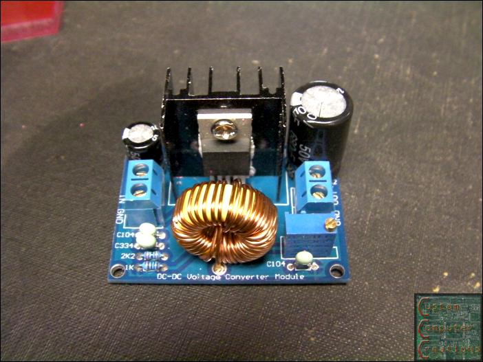
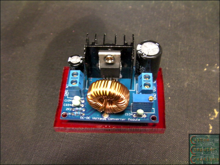
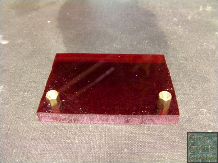
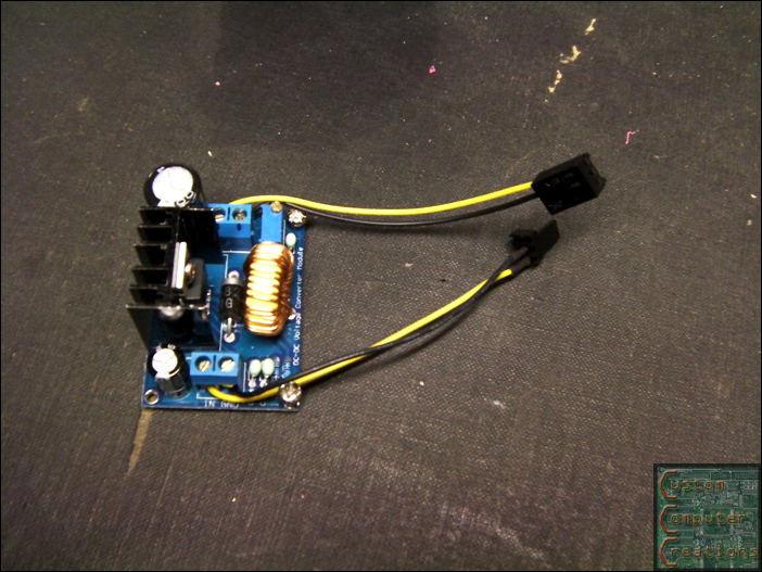
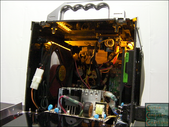
So the step-up converter showed up today, only took ~1 week from China, which is FAST. This will output up to 65VDC @3A, but it can only have a 40v differential between input and output voltages, So in my case I'll have 12v in, so max out is 52VDC. I cut out a piece of red acrylic, drilled and installed standoffs. This board has 4 mounting holes, but only 2 can be used. One is covered by a capacitor, the other is too close to other components.
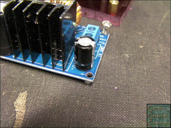
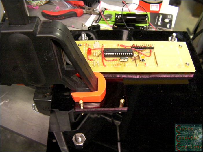
I then glued it to the top panel next to the PCB for the LCD display.
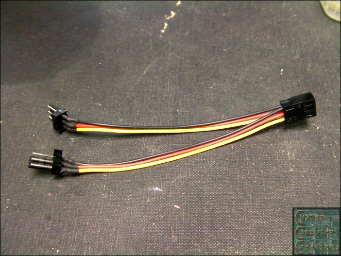
I then took a 3-pin fan y-splitter, and cut and rearranged the wires to get a male and female pigtail. One will plug into the 12v connection from the PSU, the other will go to the input on the final regulator.
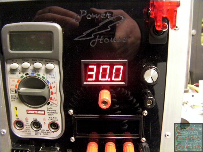
And max output voltage:
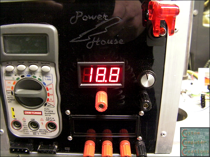
Somewhere in the middle:
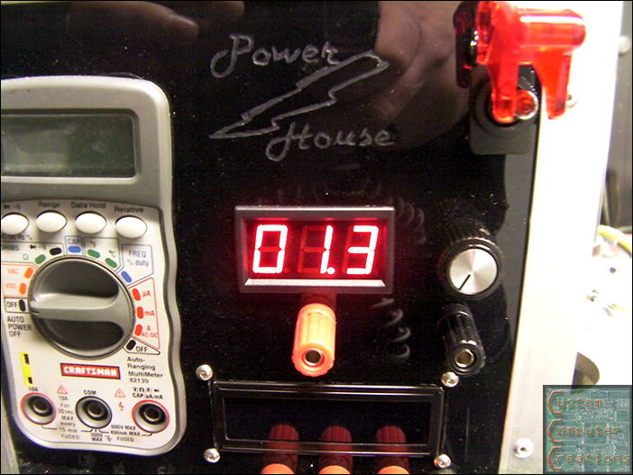
And minimum output voltage:
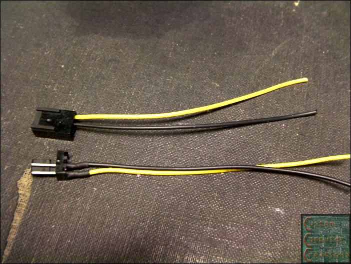
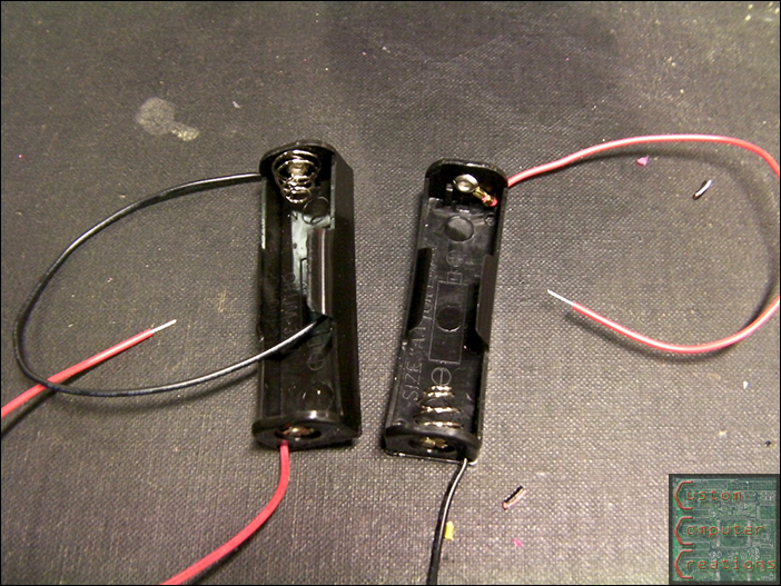
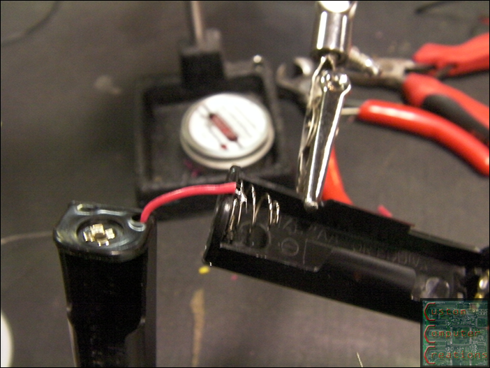
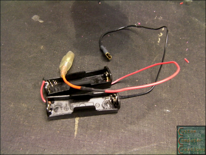
Next up I took a pair of AA battery holders and soldered them together in series, then soldered on the connectors that were originally hooked to the 3v and GND on the PSU. This will get rid of the interference I was seeing when having it hooked to the PSU.
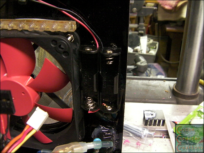
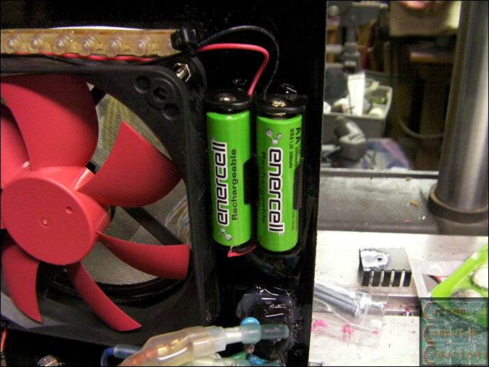
Then I hot-glued them in an easy-to-access spot to be able to change the batteries, and installed the batteries.
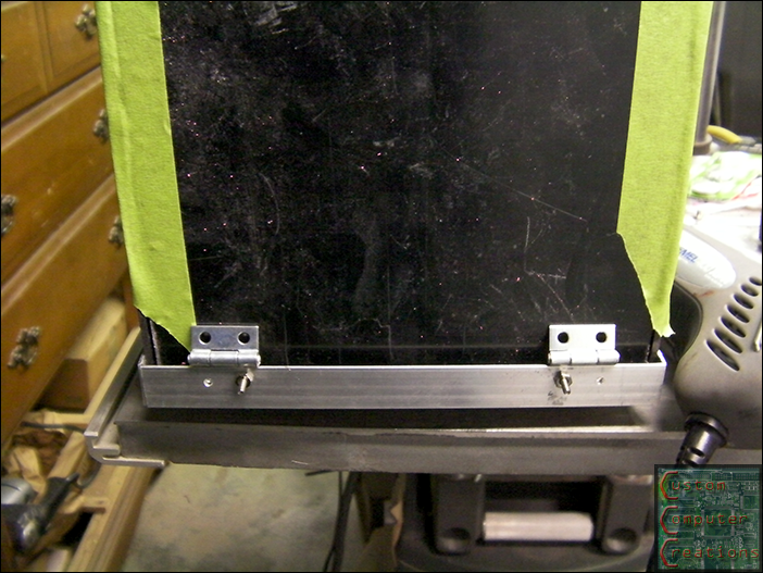
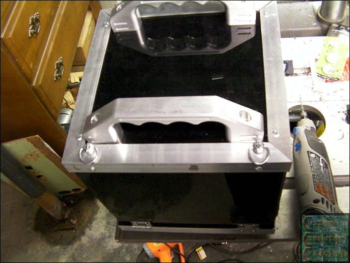
Next up I started the work on the rear door. I taped the rear panel in place to mark and drill for the hinges.
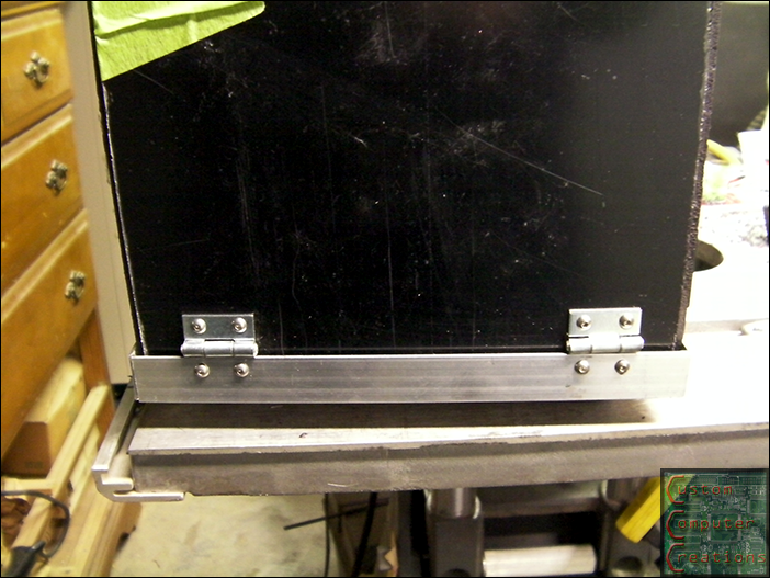
Next I got the hinges fully mounted with 4-40 SS button head screws and nuts.
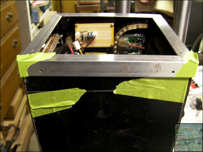
Then I taped the top angle piece in place to drill the rivet mounting holed onto the door panel.
Then I riveted in the top panel.
I then installed the 1/4 turn clips, and drilled the holes to match. The I drilled the top angle piece to fit in the 1/4 turn studs, and installed them with some spacers to take up any slack and get a nice tight fit.
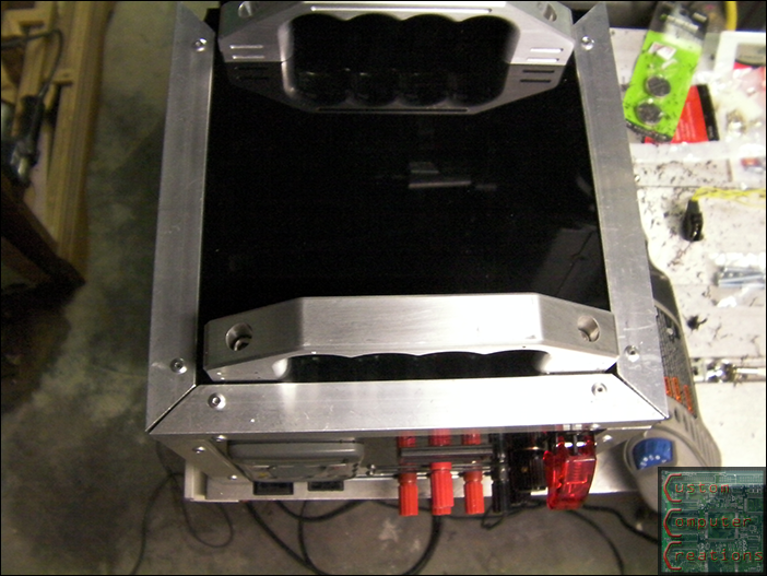
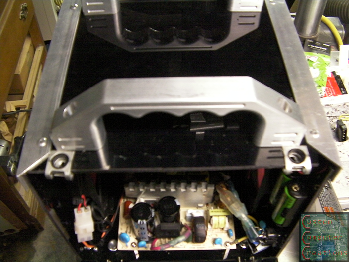
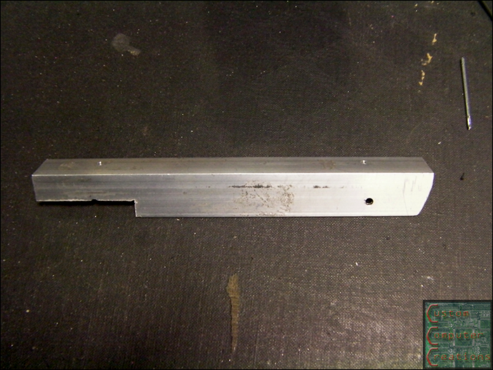
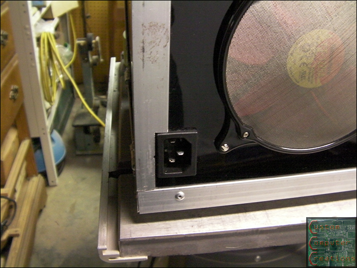
I installed the LH side vertical angle and shave the top at an angle to allow the door to open and close, and did the same with the RH side, with the addition of a notch to fit around the power port.
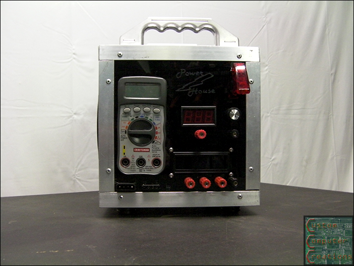
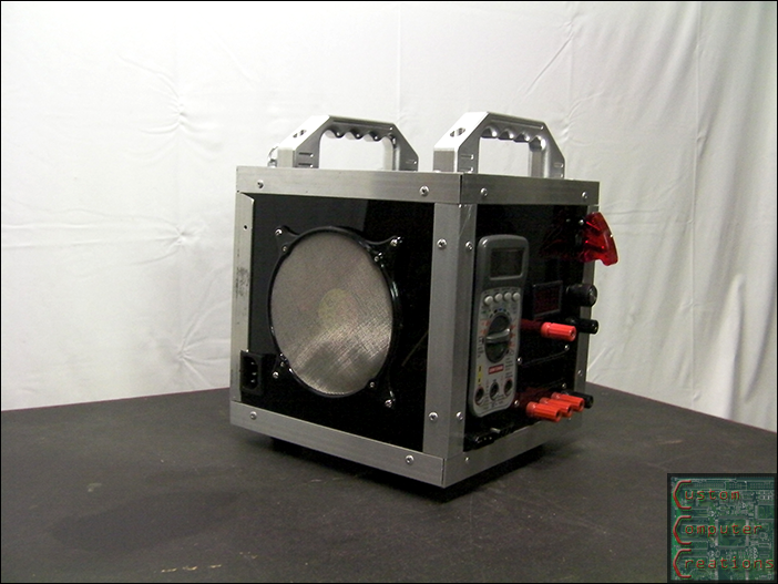
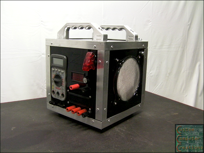
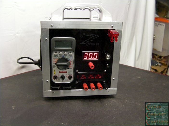
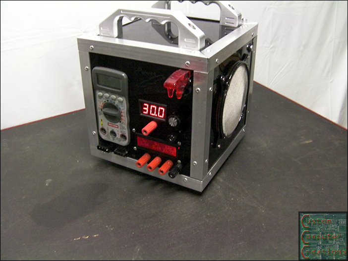
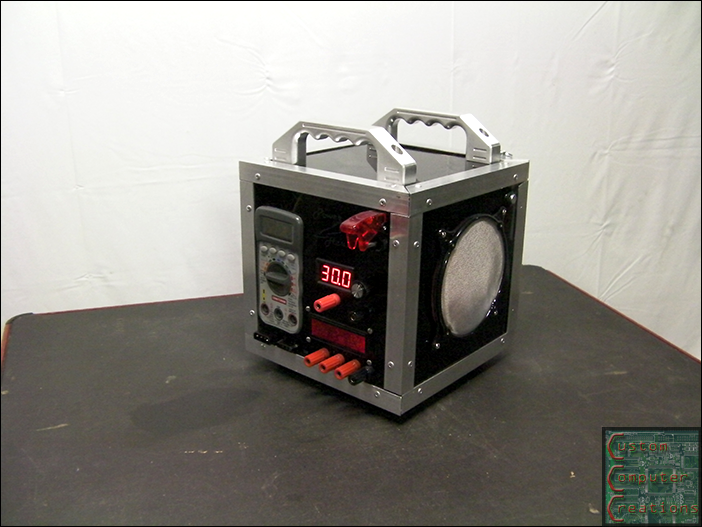
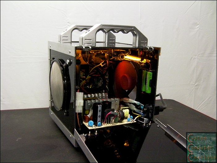
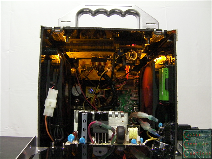
And the final pics! Enjoy! :D
This project is officially finished! Admins please move it to the completed worklogs section :D
gotta any of that black acrylic left over? haha sweet mod bud
I do actually, how much are you looking for?
Not sure yet, trying to find a used (think ugly as sin rattle canned shuttle case for $10 used) itx case for my budget mod but if I can't I am thinking of sandwiching it between acrylic. Board dimensions are 6.75 inch x 6.75 inch
well those black panels I got you can get from any RV dealership. They're actually door insert panels for RV refrigerators :D
Looks great. :up: One thing though.. I wouldn't push that DC-DC converter over 50V if I were you...assuming the circuit is what I think it is, those 50V caps will limit the realistically usable max voltage, and overvolting caps is generally a bad thing. ;)
it says it will support up to 65v, but I'm not planning on going any higher than 30 with it, and I doubt I'll even need that much, but it's nice to have the ability to get anything in between 1.3 and 30, should the need arise :up:
Well, assuming it's a fairly standard DC-DC buck converter, the caps should be stabilizing the input and output voltages, so if you try and take the output voltage higher than the voltage rating of the caps, you'll be over-volting the caps...which could get messy. I don't doubt that they said it'll go to 65V, and it might very well work at 65V for a while, but I wouldn't run it at more than 50V for any amount of time without replacing those caps with higher voltage ones. ...though, since you're not planning on going over 30V anyway, I guess it doesn't really matter all that much. :P
Congrats Will.
Congratulations, Will (if I may call you that), on the front page & Hack-A-Day features! Always great to see an awesome mod get recognized. +rep :up:
Thanks guys! And yes, Will is ok :D
So, we got two Wills here now?
This MIGHT get confusing.....
including you, 3 actually lol :D
:)
Numbers.
SXR.
Who's the 3rd? Not me.
would be me. hence the smiley.
Some great ideas here.
I am not sure how, but a 24V supply would be advantageous, maybe most easily achieved by including a separate transformer, plus rectifier & regulator which could be an adjustable type for greater utility.
Re the multimeter for digital voltage readout: that is the best & lowest cost approach although cutting the PSU panel to accomodate needs a bit of care. You also usually have a built in transistor tester & sometimes a capacitor tester & auto-ranging for a few more $$$. The other thing is that it may be better to retain the battery supply for the meter, most work on 9V & I suspect a ground connection for alternative supply might introduce spikes or other unwanted & hard to find "interference".
I have wrestled with the issue of the best & most easily used connectors when building a similar unit. At first I also used binding posts but they are a pain when a quick connection is required. Finally I decided that screw down clamp terminals were all round the most convenient, just stick your wire in the hole & clamp it without damage by a screwdown. Best of all the whole connector is pretty well protected against accidental contact by the plastic moulding. Oh yes, & although not elegant top mount is the most convenient.
I never thought about a fan (foolishly) believing that a bench supply is very rarely in use for more than a few minutes at a time. That's dumb & limiting when fans are cheap. Here (in Australia) however, you might need to incorporate a 1 mm square insect proof mesh - those damn insects love warm hard to access places.
I'd love to see more detail about low cost lighting effects.
Well done.
My final comment:
This has been a wonderful project to follow, & see how community involvement has helped.
The "24V+" solution is great even if it meant a "board from China".
I was not surprised to see you experienced some "interference" on your meter (see my other post) but pleased you sorted it.
Personally I don't like the cramped space but recognise how that came about.
Also I don't like the hard edged box design which I think proved time consuming to make, although very flexible, & the materials are easy to work.
All round a very well made & super useful bench PSU.
Well done & thanks for the ongoing detailed explanations - I guess that applies to everyone here.
Thanks for you comments Peter and thanks for checking it out!
ok well now that the weather has warmed up I've noticed the readings are off again. The warmer it gets, the lower the readings. It'll be ~75º in the room, and with the fan in the window as night comes it cools down to ~65º and the readings go up by a volt or so on the 12v. right now it's ~77º, the 3v is reading 3.3, 5v is 4.56 ans 12v is 10.47. The actual voltage is correct though.
It would appear that I need to make some sort of temperature compensation for the ATMega. Apparently it's ADC is affected by temp. More on this later.
Resistors change values with temperature changes. Try using precision resistors
Great project and documentaion.
What LCD did you use?
Thanks
I'll look into the precision resistors, thanks. I also read somewhere that I need to disconnect 5V from the AREF on the ATMega as well but haven't gotten around to that yet.
The LCD I used is this one: https://www.sparkfun.com/products/791
Super most excellent benchtop psu
Any chance you can provide the code for the arduino and/or links for that side(lcd display) I got my daughters (7 and 5) into these arduinos and this would be a great project for us before we get too much more involved(we need power)
Sure I'll see what I can dig up for you, give me a couple days :)
Many thanks
Any luck? I am mostly interested in getting the lcd to arduino code
Sorry for the delay man, things have been crazy over here. Here's the .pde of the code, short and simple. You may need to tweak some of the values depending on what % resistors you use. What I did was hook a multimeter to each line to get the actual voltage then adjusted to code until it matched.
right-click and save-as
http://www.computersandcircuits.com/...powerhouse.pde
I do not know what has happened to the pictures ... Can you please send me the voltmeter scheme based on Arduino?
many thanks!