Very cool looking project so far!
The only thing that concerns me is the logo.. it looks an awful lot like the one for PPI (Precision Power).

Printable View
Very cool looking project so far!
The only thing that concerns me is the logo.. it looks an awful lot like the one for PPI (Precision Power).
@NightrainSrt4: Yeah, it's funny: When I started my browser the YouTube tab was still open in the background and I thought someone was peeing in front of my window... :think:
@Luke: :dead: ****, you are so right with that logo. But I am from Germany and I have never seen this logo before. I think I will drop them a mail: They should get a new corporate identity! :devious:
Verry Interesting. I like how you've used the Logo to divide the water there. .Looks Kewl! Also glad to see that you're back on this project after the meltdown. +Rep
Omg I Feel That A Update Is Comming In A Few Seconds
Hey FrooP, where did you know that from?? :think:
Well, it's only a small but important update:
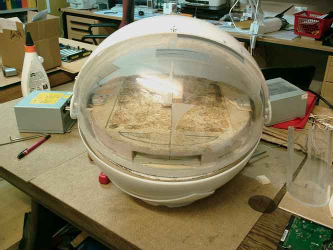
My constructions seem to fit :D
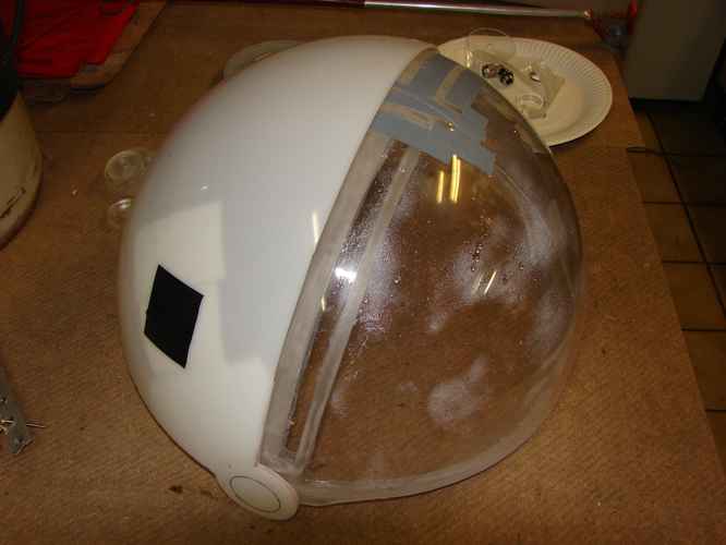
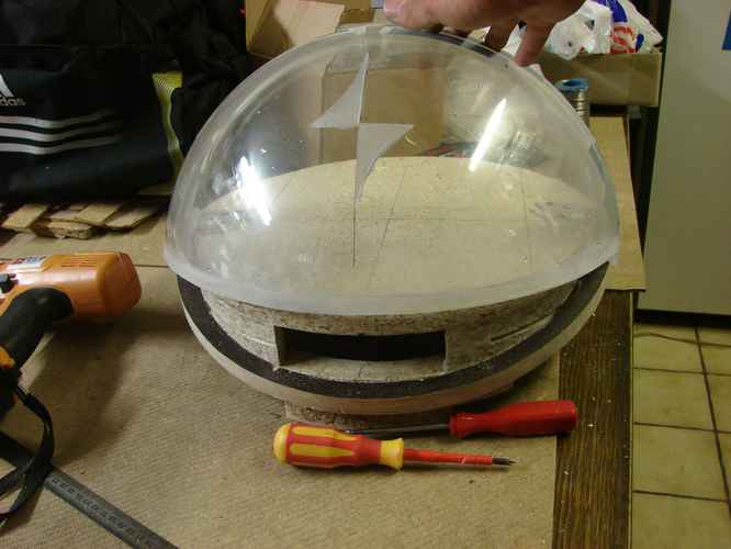
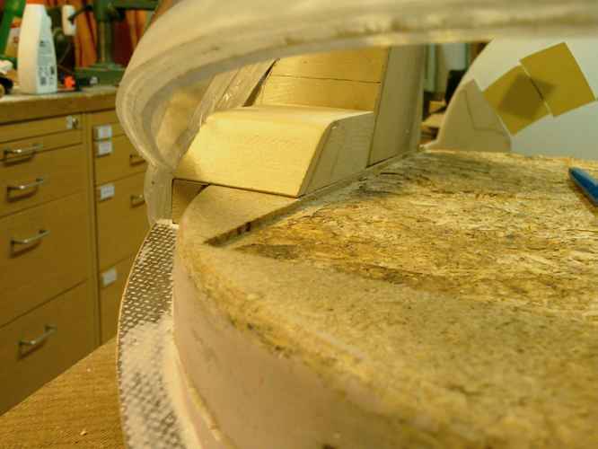
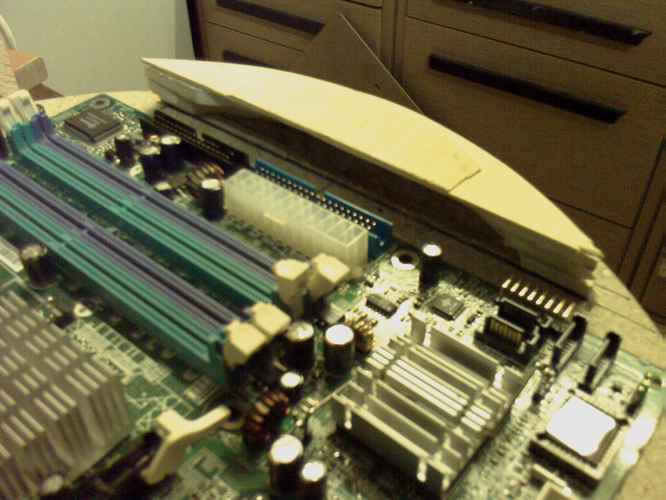
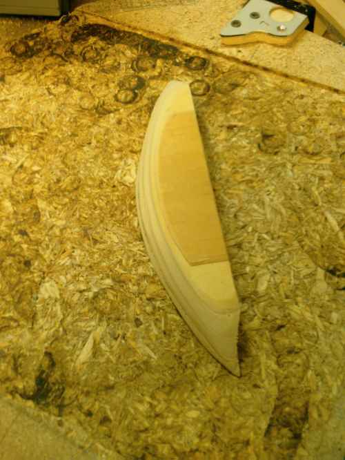
I tested today how the Visor fits into the outer quarter sphere. What should I say? Look at the pics and the video:
I will close the gap between the Visor and the sphere with something flexible like foam or fabric. The adhesive tape you see is only for protection purpose.
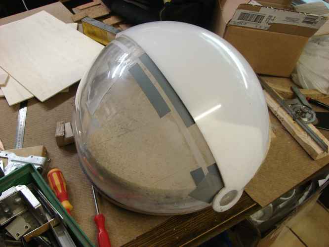
Closed:
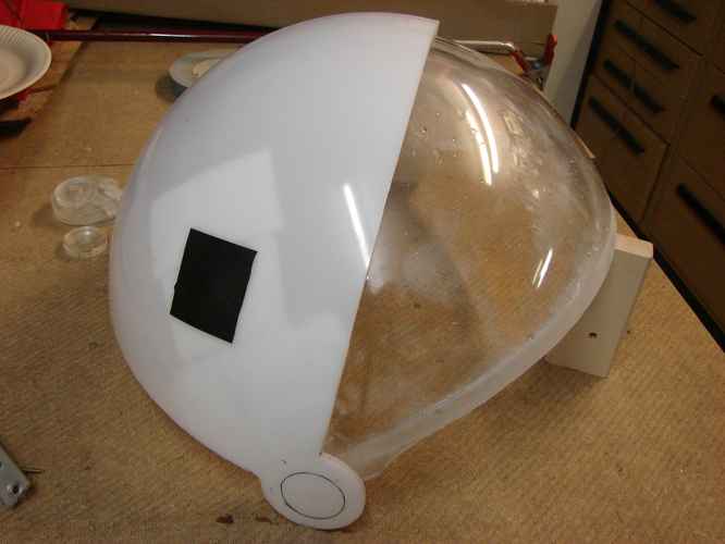
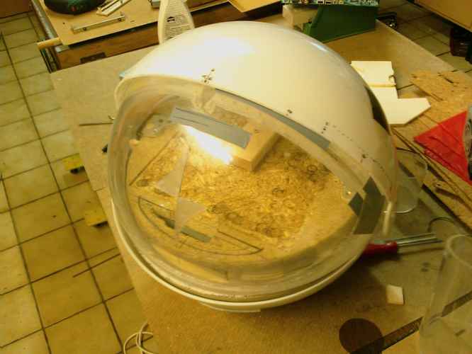
Open:
To make the video, I added some provisional hinges made of two needles and some cork.
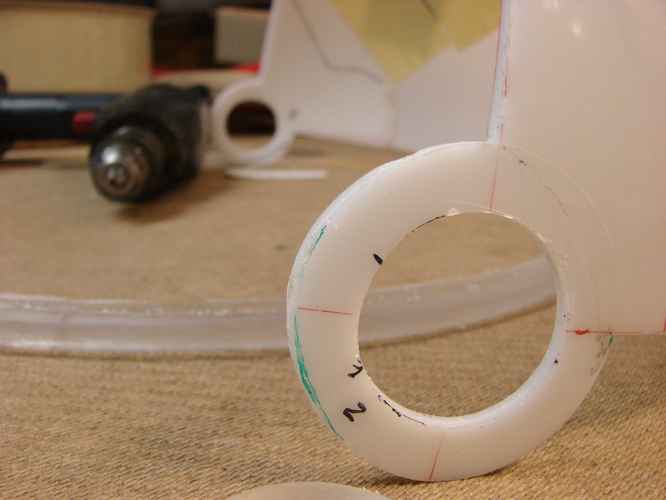
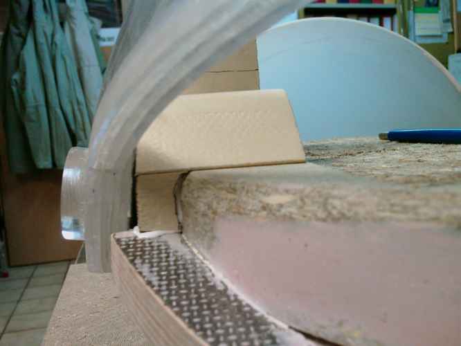
When I assured that everything fitted quite well, I started to work on the real hinges:
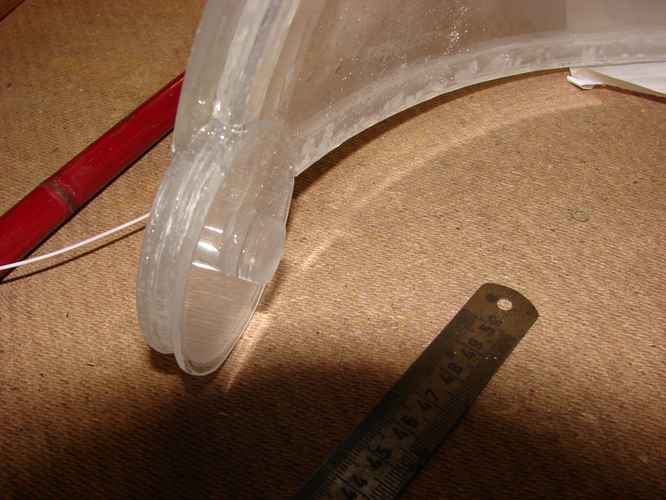
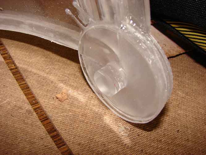
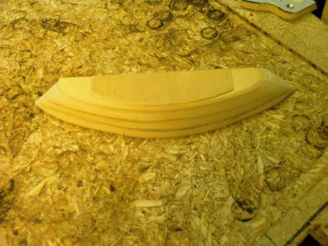
The holes in the upper quarter-sphere are the mountings for some plexi-disks that get fixed to the Visor. You can see them some posts ago.
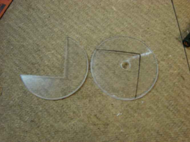
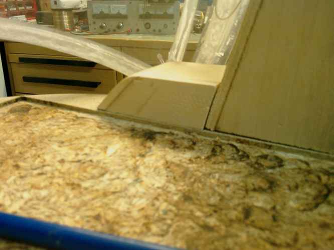
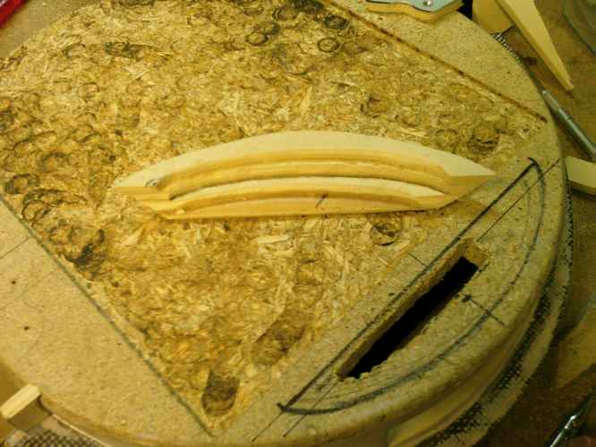
The parts you can see here are the last parts missing at the visor. They make the base for the plexi-disks through which the real water-hinges will lead:
Well, I glued the stuff and now I have to wait till tomorrow.
See you soon,
Squelsh
thats nice:D i especially like the water in the visor xD... green fluid? and uv would look more than cool!
Hey p0Pe, thats exactly what I am going to fill into the visor :)
I'd love to see how it looks but I don't have enough UV-color for a test...
Today I continued work on the wooden baseplate. But when I compared the visor to the plate I was shocked!
The Visor isn't spherical any more. All the layers glued on the inner sphere made it elliptical :mad: That makes it necessary to build an elliptical Orb...
The difference is only about 1cm. Thats not too much compared to the 40cm diameter, so I hope no one will notice it. But it makes things even more complicated...
Pictures of the new baseplate will be added later.
See you. Squelsh
Sorry if you have been waiting for the announced pics. They somehow got lost :(
But they looked pretty much the same as the last two pics from http://www.thebestcasescenario.com/f...8&postcount=13
Only the material changed from pressboard to hard wood.
Well, I have some new pics instead:
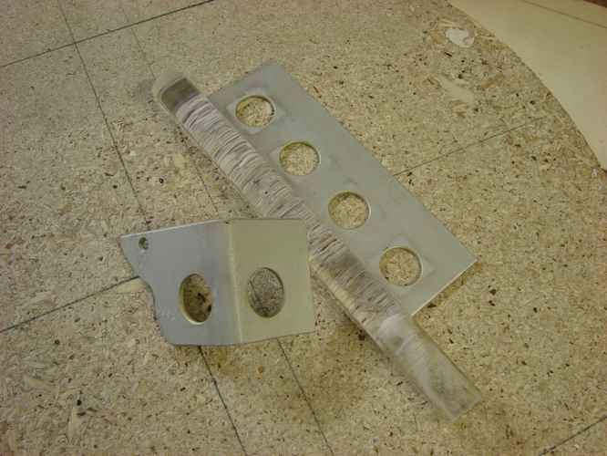
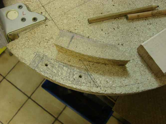
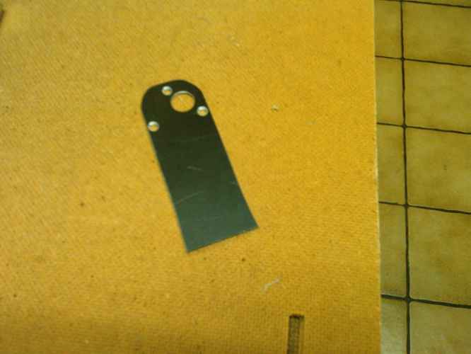
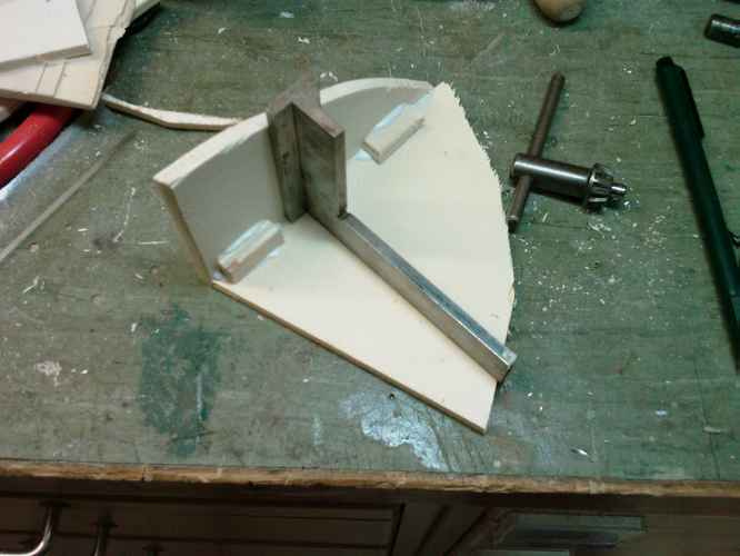
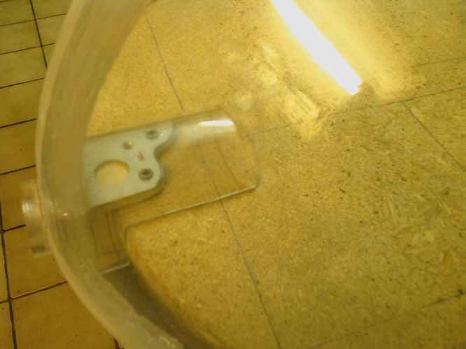
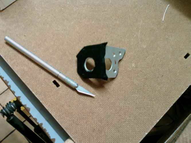
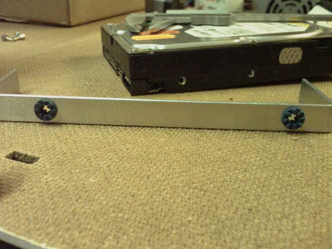
These are the parts for the hinges that hold the visor. No water goes through them. I found a plexi-bar and an aluminium piece that already had holes with the perfect diameter for my use. I cut the aluminium and bent it. The funy shape is the result of the former holes that were in it...
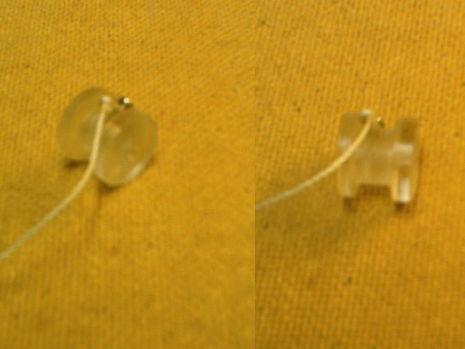
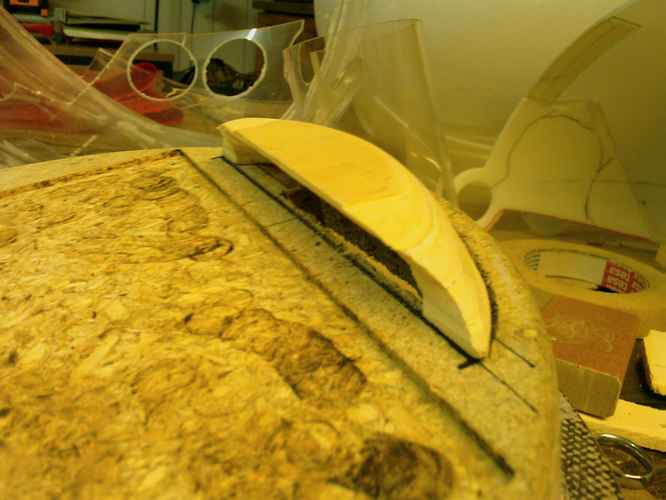
Then I cut two slices from the bar and glued them to the rotation center of the visor:
I needed some spacers fot the hinges that were made of wood. You can barely see them here: I will glue some felt on the aluminium so the plexi slides easier.
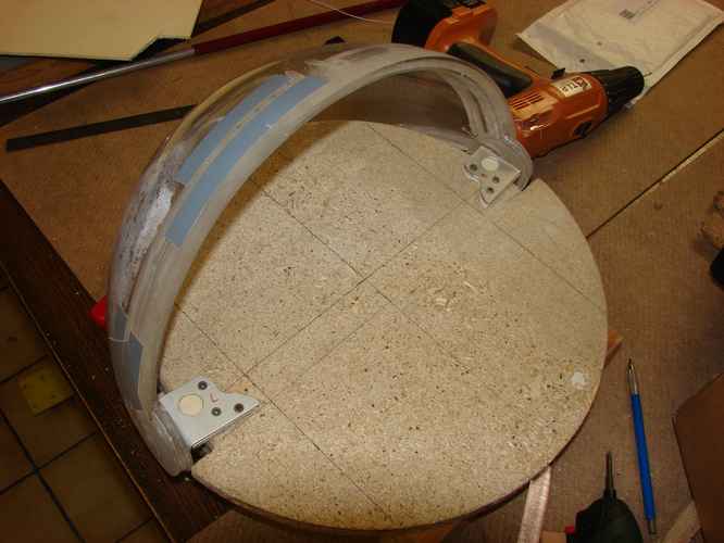
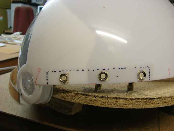
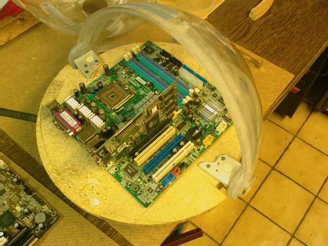
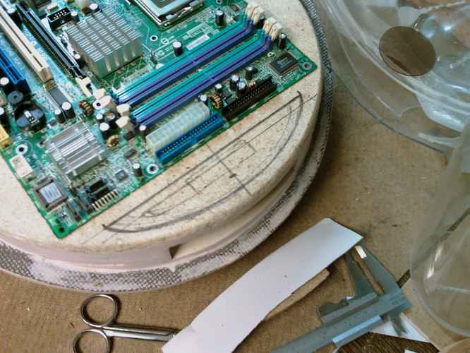
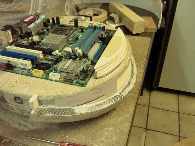
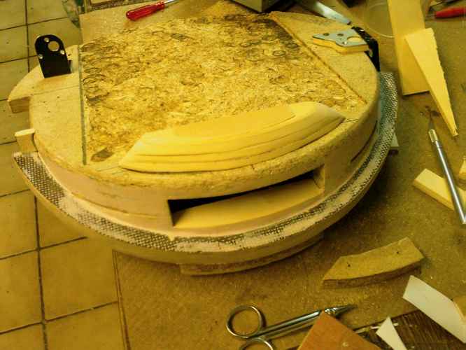
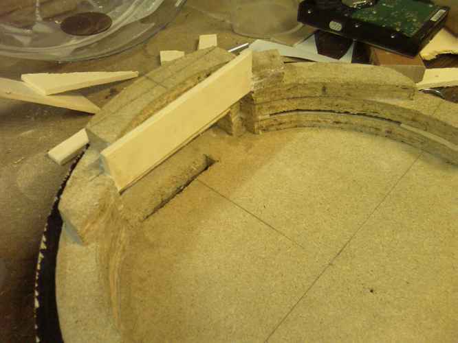
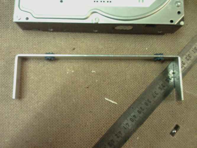
I needed some time to figure out the best angle to fix the hinges to the baseplate. The lines next to the hinges show the dimensions of my MicroATX MoBo.
And here is the result:
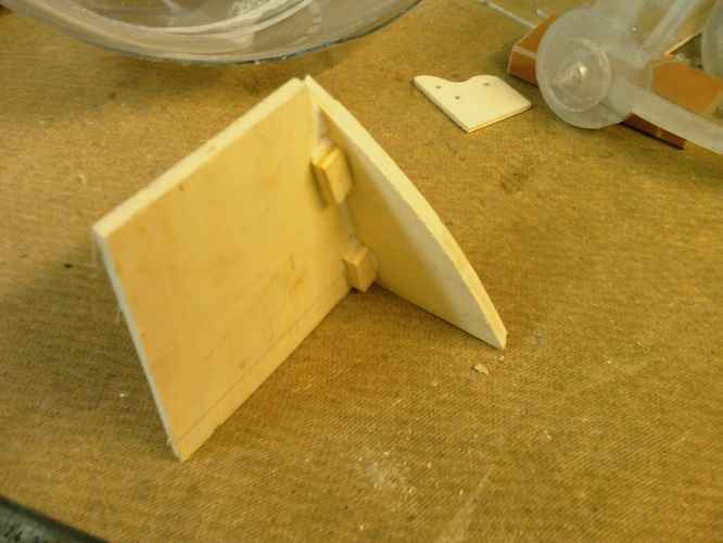
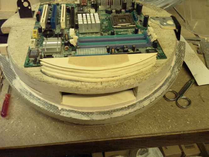
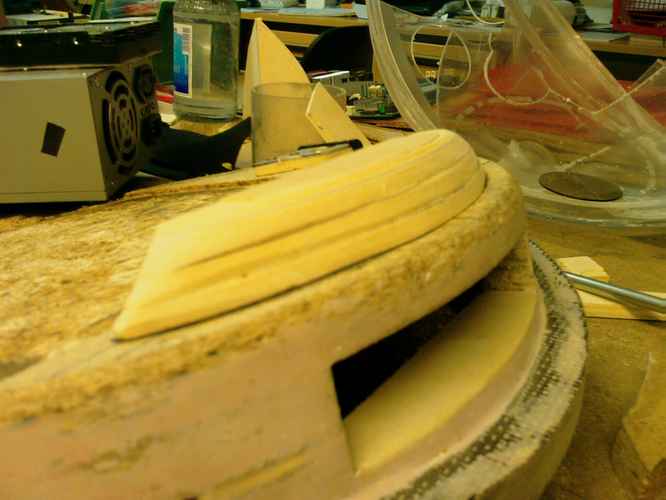
Visor opened: The dark brown wood you can see is the new rim made of hard wood. It will hold the lower hemisphere.
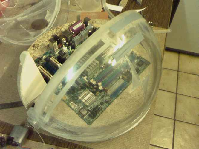
And closed with the outer sphere on it:
Next time I will smooth the baseplate and the rim with bondo and think about a nice cover for the hinges that will also cover the cables from the MoBo.
I think I will need a strong motor to move the visor. It's heavy even without water in it...
Well, after month of work on the visor and other single parts the project now starts to take shape :banana: Comments are verry welcome!
Cheers,
Squelsh
oh yeah 8)
Put very nicely. This is an awesome mod.Quote:
Originally Posted by FrooP
Thanx!
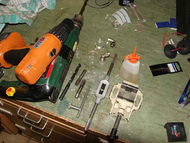
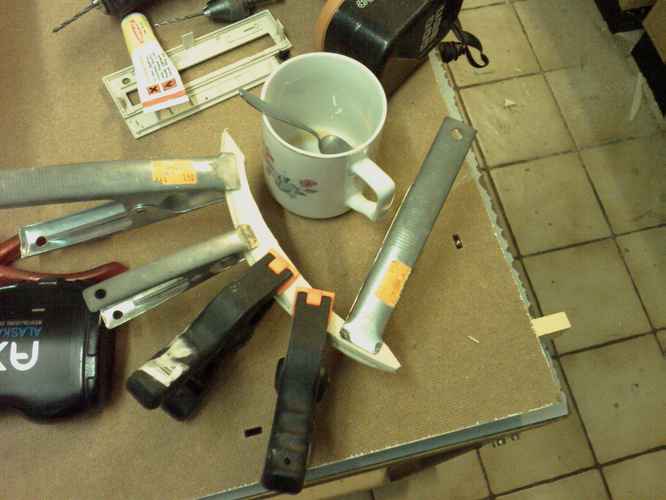
Today I got the a tapper so I could do the thread cutting for the hinges.
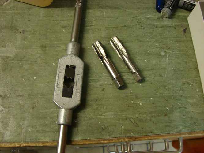
These are the tools I used:
I needed a pre-cut and final cut:
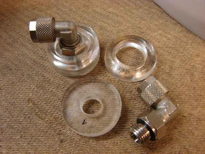
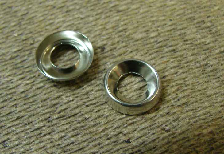
Last pieces for the res:
I glued the disks with the threads to the visor. Cover-rings will follow tomorrow. The hinges you see can be rotated. But I don't think I will need this, because the hoses are outside the sphere and can bend when the visor opens.
That's it for today. See you soon.
This is a cool mod. Very original design!! I like it a lot. 8)
2 days free of work ==> time for a bigger update!
Part 1: Mounting of the hemispheres
I found some nice spacers so I did a test on how I could fix the upper hemisphere.
First some piece of wood in the right 15 degree angle:
Please ignore the professional way in which I used the nuts as spacers :)
And the spacers fixed with tape to find an appropriate interval.
Okay. Thats not really exciting, only touch-up work. So watch out for the next update.
Part 2: Baseplate improvement
Fortunately I had to go to a computer store on Wednesday to get my boss laptop fixed. They gave me an old Micro-ATX Board for free, so I have something to work with.
AND: I could test ride an SEGWAY! These vehicles rock!!
Home again I did some Bondo work with the baseplate to get rid of the ugly pressboard surface. I don't think I need to show you pics, as there are enough in the forum.
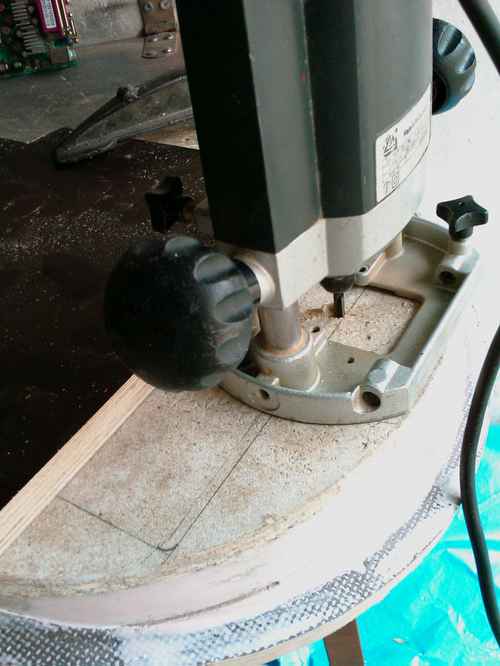
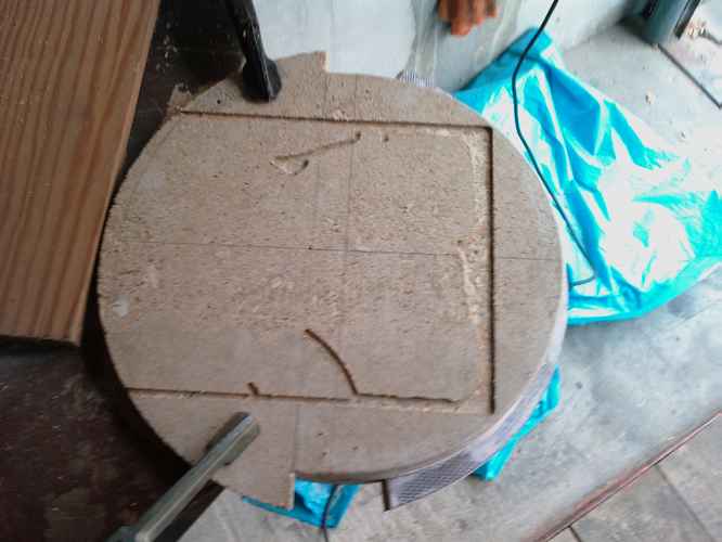
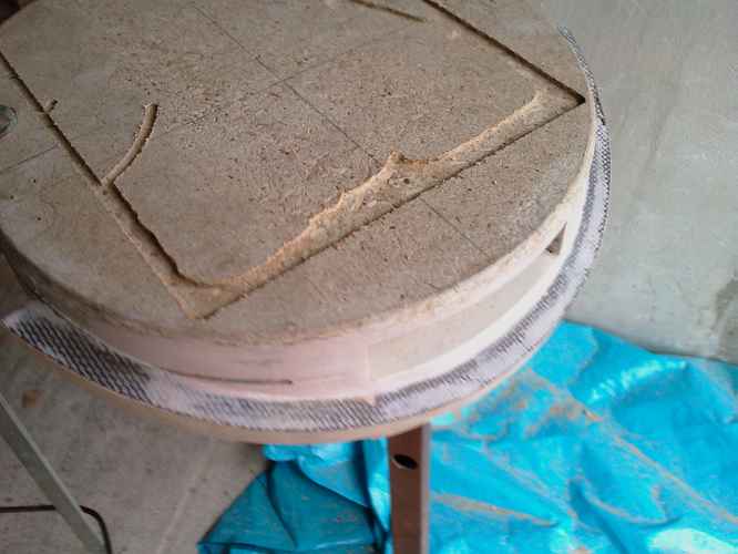
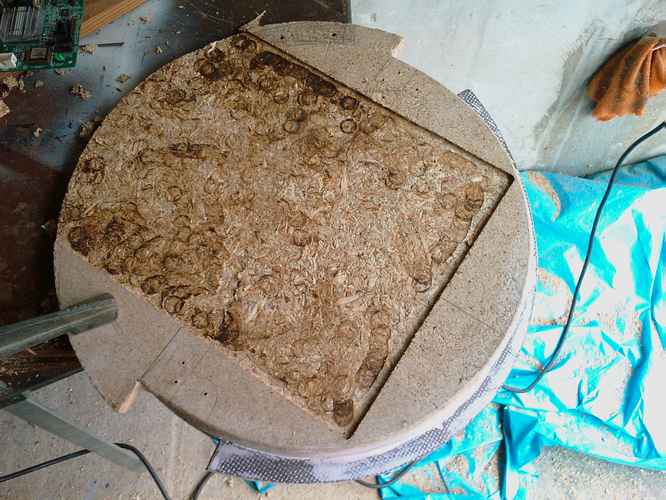
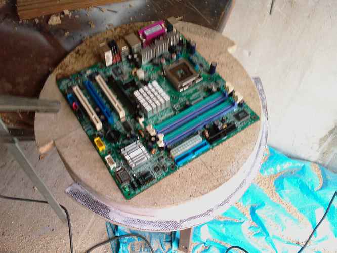
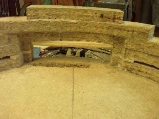
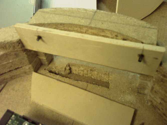
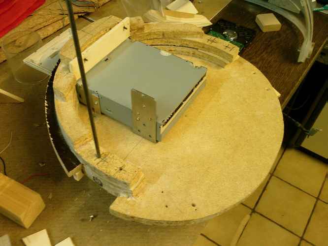
The next step was to create some kind of basin for the motherboard. I don't wanted to only screw it on top of the baseplate.
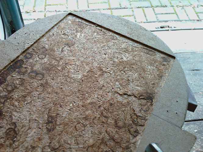
No big deal with the hand mill:
I started with the outline...
...and carved out inch by inch.
Result: The smell of burning wood (:
And it fits :)
I like it, how about you?
*waits for further updates*
i know things :P
...what...lol...:D
BTW: Pics are made with my new toy:
HTC Kaiser :D
3 MPixels Autofocus. But no chance for good macro-shots or low-light-shots :(
Besides this, the 400 MHz, GPS, HSDPA and all the other features are quite cool!
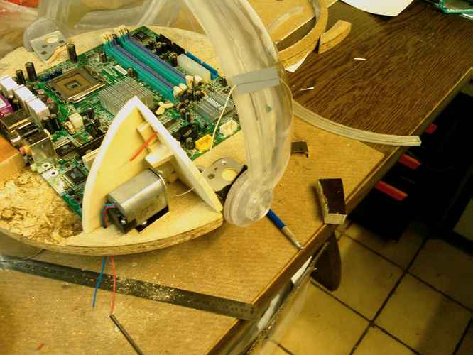
Part 3: Motorization of the visor:
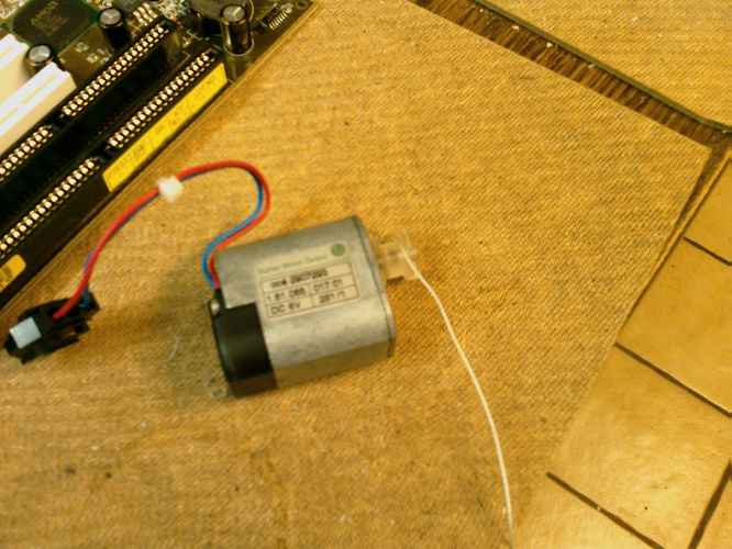
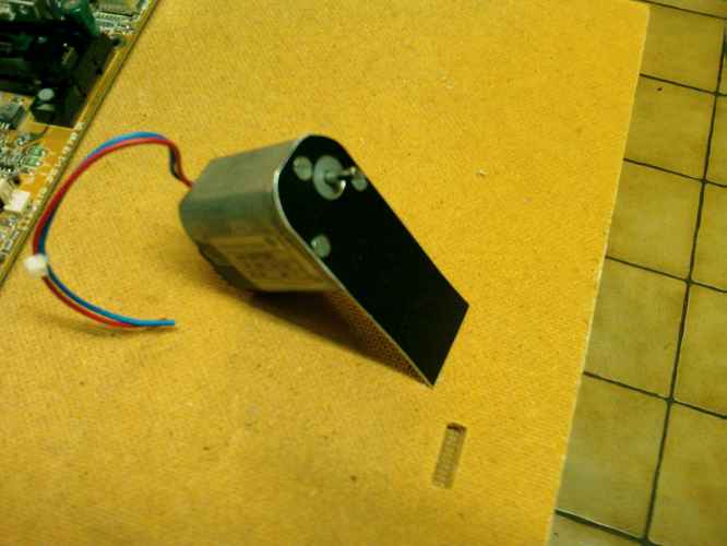
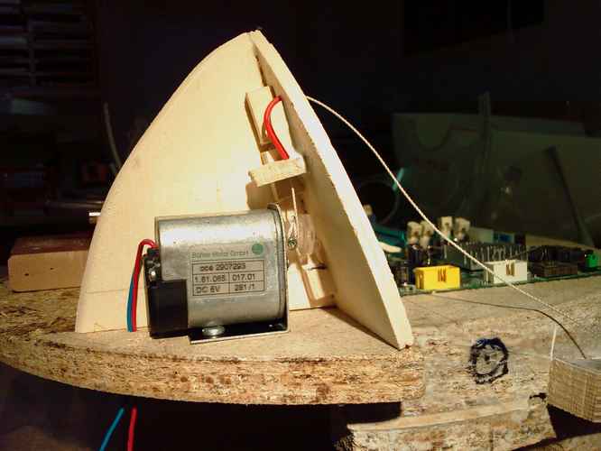
Finally I found the right motor for my needs: It has a built in gearbox so it runs slow and with a lot of force at 6 Volts:
By lathing a piece of a plexi-bar I produeced a small spindle to wind up some thread. I drillled a hole into it to support a screw which keeps the spindle from rotating on the axe and to knot the thread on.
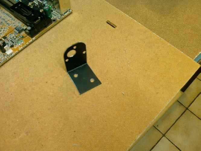
The support for the motor is made of aluminium:
The motor should find his place left or right of the motherboard in the upper hemisphere, because I know space in the lower hemisphere will be rare:
A housing was needed. Not an easy task, becuase it needed to fit inside the sphere...
I started with some wood that I shaped millimetre by millimetre. Held it inside the sphere, marked the spots and then filed the wood.
The housing at it's place:
Time to get the motor inside:
I had no space to mount the motor in an other way. So the thread has to make a 90deg turn. To minimize the friction I used the red hose and a shape of wood that produces a soft bending.
First test:
Opening:
and Closing (it's not smooth, but thats only because the electric flow is interrupted):
Seems to do what it's supposed to do! :banana:
Part 4: Covering the hinges:
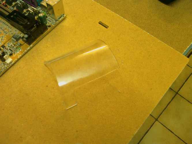
As the hinges should not be visible I experimented with a plexi tube that I wanted to frost later. Really annoying to find the right shape. Same game as with the motor housing. Holding it in place, marking some spots, filing a little and start over...
Well, it fitted, but I did not like it... The round shape inside would not have fitted to the motor housing.
So I went on with wood and glue and came up with this:
The gaps will be filled with Bondo.
Better than the plexi, isn't it?
ive got seven words for you
H O T S H I T
YOu could also put a small wheel or something where that rope (or whatever) threads through, just rig it so that it doesn't pop off. That'll reduce the friction for you.
You mean seven letters...Quote:
Originally Posted by scar~face
But i agree, friggin awesome man.
oooohhh yeah, i forgot about this mod. looks like its coming along realll nice! +rep for more work
This mod is of da chizang!!!!!
@Ryoken: Thanks for the suggestion. But I don't have the space for a wheel. And the solution with the hose works great. Nearly no friction.
Well, last day of my 4 days-long weekend. One more update for all of you. Thank you verry much for your comments!
What I forgot to post last time: Improvement of the hinges with some felt to reduce friction when turning:
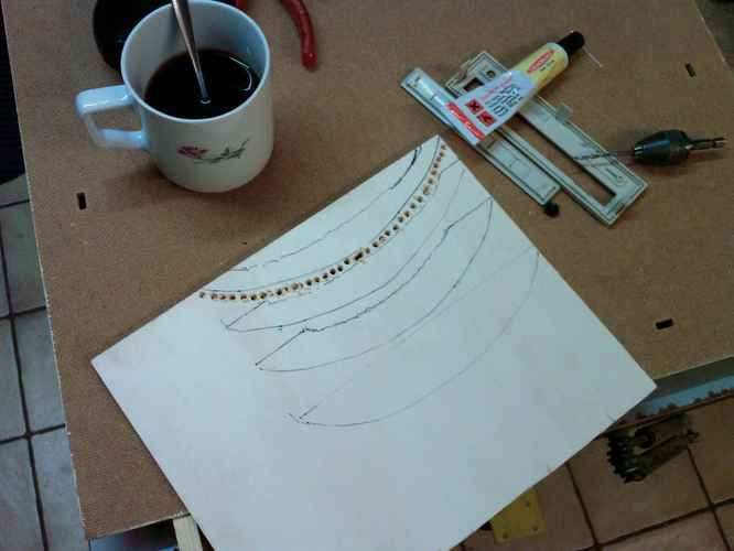
Today I spent my time with arranging the hardware inside the lower hemisphere and with a cable guide for the MoBo cables. First I drew the outlines on the baseplate and experimented with some cardboard.
Then I copied the form from the cardboard onto some wood and cut it out.
(Yes, needed some coffee :) )
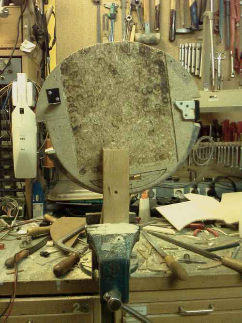
Glueing the first parts together
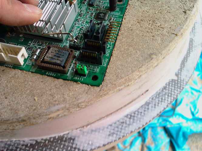
It gets more and more complicated to fix that thing in the vice. You can see the holes for the cables. I made them big enough to fit the power connector, because I dont like the idea of soldering all those cables if i remove the connector...
Here you see some shots of the cable guide in beta stadium:
It will cover the big holes.
After some filing it looks quite good. I will smooth it out with some Bondo of course.
And in place:
And from the inside:
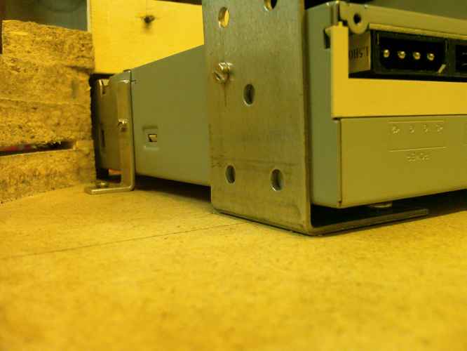
Now to the hardware part:
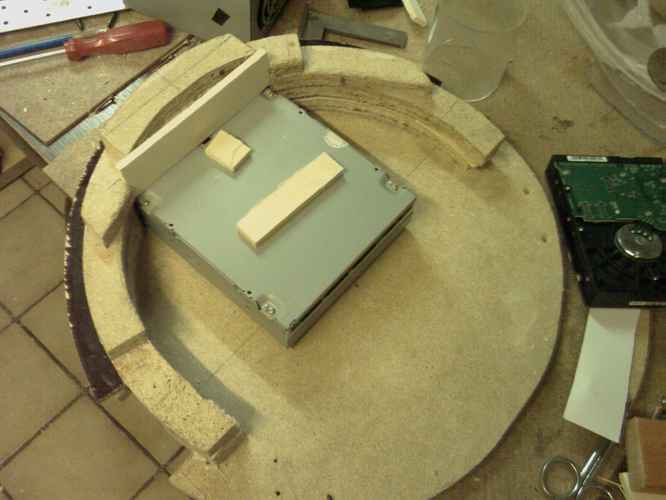
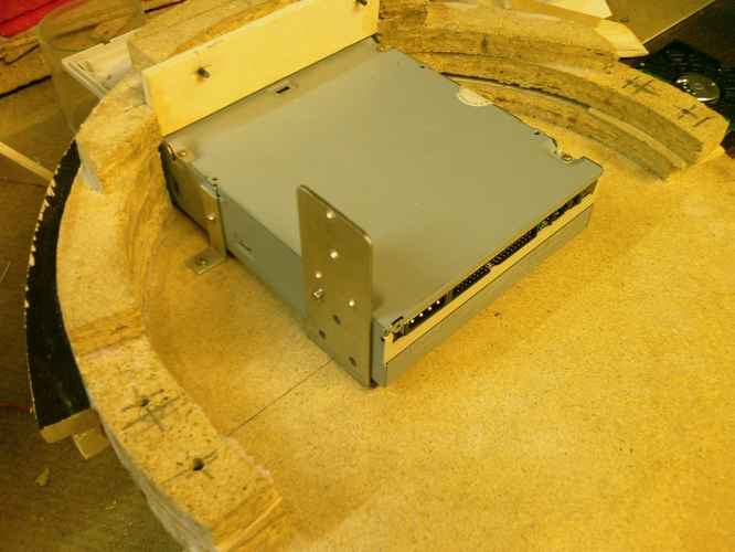
First of all, I expanded the space for the DVD because the cables from the MoBo have to fit inbetween the baseplate and the DVD.
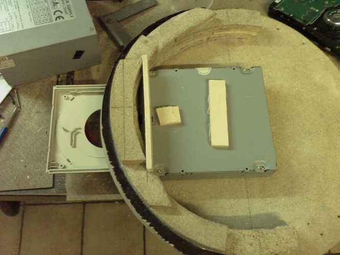
Things fit better, than I expected. In the original plans, the harddrive was fixed parallel to the DVD. But I figured it fits better in a 90deg angle.
Here are some shots of the hardware layers:
Baeplate and spacers (missing in picture):
DVD and spacers:
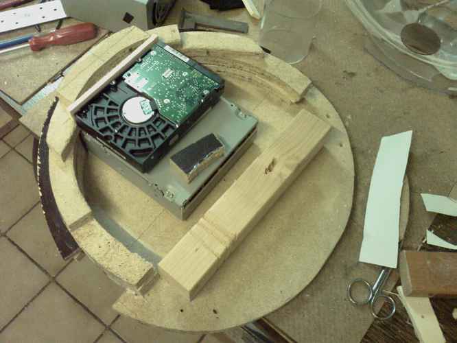
Above the DVD I glued in a piece of wood to carry the Harddrive.
Harddrive and spacers:
And the power supply. Its ventilation will suck air over the Harddrive.
And finaly the lower hemisphere:
IT FITS! :banana:
All hardware I play with is old stuff and not the parts that will be built in. In my plans I had to cut a piece of the lower hemisphere away for the power supply. With the new arrangement I perhaps only have to add some holes for the airflow :) Perhaps I should add: The baseplate lies upside down in the pics. The hardware will hang under the MoBo...
Well, this weekend I could work a lot and I think 50% of the work are done. I'm really looking forward to buy the rest of my watercooling stuff. But I think I will first paint some parts and make some good pictures to send to some firms. Perhaps I can get a sponsor or two for the expensive parts. That would be verry nice, because my budgets gets lower and lower...
I hope you write some more comments, questions or suggestions.
See you soon!
Squelsh
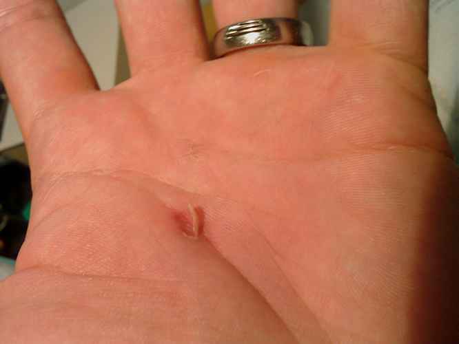
PS: That happens, if you do too much filing :hurt::
looks nice, gonna looks awsome with some paint and filling:D
His hand or the case? :pQuote:
Originally Posted by p0Pe
both:p... red paint for the hand:DQuote:
Originally Posted by xRyokenx
You sure that strawberry Nestle syrup isn't better? It looks more realistic than red paint. :pQuote:
Originally Posted by p0Pe
well... he could make a window of acrylic and mesh and backlite it with tons of leds?... would look sweet xDQuote:
Originally Posted by xRyokenx
I don't even know what in hell we're talking about anymore, lol.Quote:
Originally Posted by p0Pe
who cares:DQuote:
Originally Posted by xRyokenx
LOOL :D
My friends always lough at me: "You add LEDs to everything you can lay your hands on!"
But: I would be the first one with acrylic, mesh and backlite in my hand! :alien:
BTW: I prefer Nestle Sirup...
Quote:
Originally Posted by |NQ|Squelsh
how do you apply for a computer part sponsorship?
Hi Fallen,
I can't tell you right now. But I know that many guys get sponsoring from big firms like ATI and by small resellers. So there must by a way. But I am quite sure that there is no formal way. Just get in contact with the firms you think you can offer them some promotion. They wont help you if you cant offer them a reward.
Perhaps you better ask the people here that already got sponsored.
the problem here is that we dont have alot of lans here in alaska. our states total population is less than 675,000. i know of only one lan that actually has any advertisement.
I found some more pics on my mobile. They show my progress on the hardware-mounting. The parts are quite the opposite to my CUBE 2 project. While stuff had to look smoth in my CUBE 2, the interiour of the lower hemisphere is absolutely pragmatic as there wont be any window.
This is the counter-part of the harddrive fix. But I think I will change this for a better vibration absorbability.
I am quite sure, that the wood would transport the HDD vibration if I keep it the way, that the disk will be plugged onto the black sticks:
Here are two pics of the DVD-Mounting. You can see the gap between wood and DVD. This is for the cables coming from the MoBo.
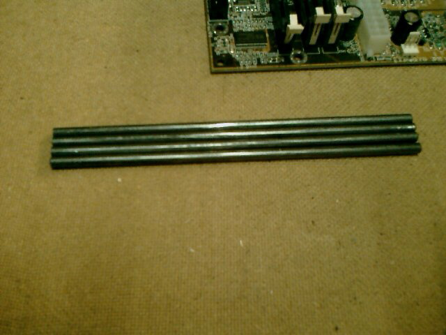
Here you can see one of four metal bars that will connect the baseplate with the stand.
I really had problems to find the position in the lower hemisphere where I had to drill the holes for the bars. Because the spheres position is only exact when it lays completely on the baseplate. But then you can't mark the position from the inside of course... I solved this problem by adding a light source inside the sphere and projecting the shadow of a shorter bar on the sphere. I could see the shadow from outside and mark the position for the hole.
These are previews of the parts put together. Looks lousy without painting and hardware inside... But I am quite happy with it and I do believe now that I can finish that thing :)
Today I hope to finish the bondo works on the baseplate, so I can start painting tomorrow.
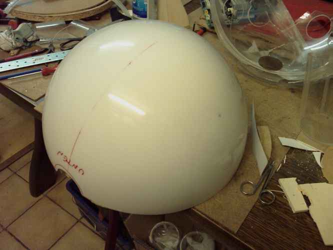
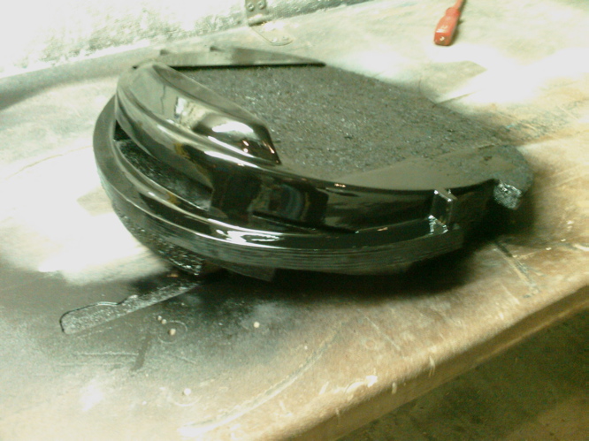
YEAH!! First piece is painted and looks amazing :)
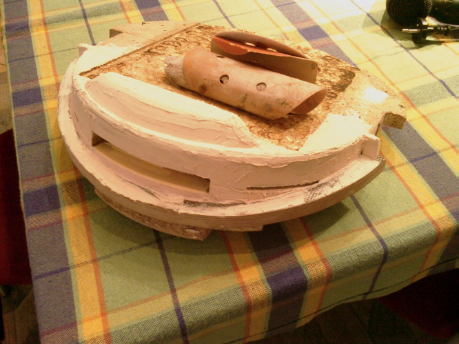
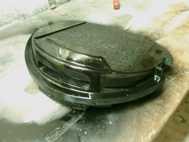
For direct comparison:
Bondo Unpainted:
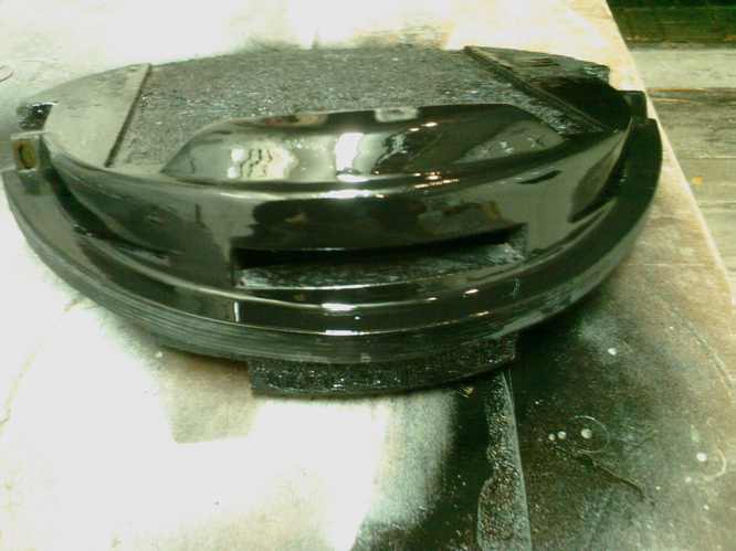
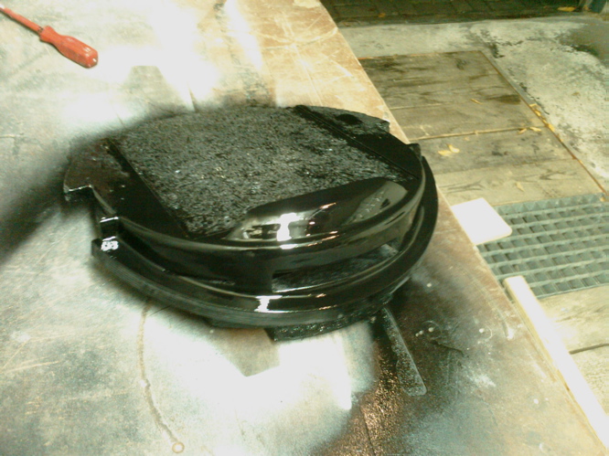
Sanded and painted:
What do you say? Does this look like pressboard any more? The suface got so f***ing smooth after 3 hours of sanding :) I think this was worth the work...
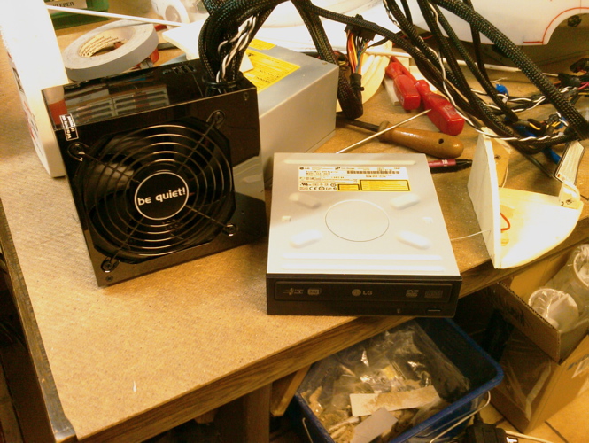
Here is a pic of my DVD (LG) and the Powersupply (BeQuiet 500W) :
And the metal-bars that will connect the baseplate with the stand.
I bought some new pressboard to build the stand from. I plan to make two different stands: One for LAN-Parties and CaseCon-Competitions (a big one like in the renderings on the first page) and a smaller one for my desk.
Thats it for now. See you,
Squelsh
Dude, That looks friggin kick ass! I love it. Good job on the bondo, sanding and painting. It almost looks like a molded plastic piece. -Very nice indeed!