Nice desk mod :) . Can't wait to see more of it.
You're so damn right about that. Hm, might going to copy my worklog to this place to :) . Don't know why I didn't thought of that before... What do you guys think?Quote:
Originally Posted by _ferry_

Printable View
Nice desk mod :) . Can't wait to see more of it.
You're so damn right about that. Hm, might going to copy my worklog to this place to :) . Don't know why I didn't thought of that before... What do you guys think?Quote:
Originally Posted by _ferry_
Nice shelf you have there with the LEDs. Looks great!
I think you should do it and stop hijacking _Ferry's worklog. ;)Quote:
Originally Posted by Jeroenotje
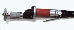
Tools are done :D
Building time of the syringe: 7,5 hours.
Next:
Something like this.
that's cool.
Very cool +Rep
Dude you doing a friggin great job man. Damn.
love the syringe, i skipped to the last page and thought you bought it.
Till i saw the work time =o
I thought of some other ideas you may be interested in...
Bone Saw
Rotory Bone saw
Maybe you could have an x-ray somewhere...
Op room lighting?
Great Ideas, Jon...those would really complete the look! But with all the metalwork on the alien, maybe some metalworking tools too? Off the top of my head, maybe Jon could think of a way to make a welder look like a surgical tool?
:D I love this project. Totally original.
-Dave
Hey, thanks for the ideas!
The only one which i already thougt of was the lights. More into a shape like this:
With a adjustable arm made of plastic/metal. As light source a 1watt led with a few smaller leds surrounding.
Metal-working tools: yes, some of these:
In a nice modern alien-look CNC style. Very usefull since his bones are connected with bolts and nuts.
Anyway, i've got a new update. I wasn't in the mood of the intensive work to create another instrument, so i started with modding the monitor.
The idea is, that once i have a little start i can think of some ideas to work out on it. Drawnings doesn't always give you all the ideas you could really use, while modding you create things and solutions you'd never thought about.
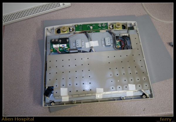
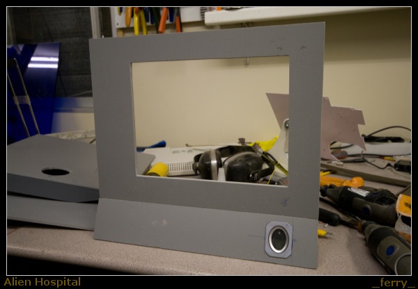
Let's start with some plastic sheet which i grabbed out of the garbage @ work and a 12" trouchscreen.
And after some cutting, straighten the edges and gluing them together we have this.
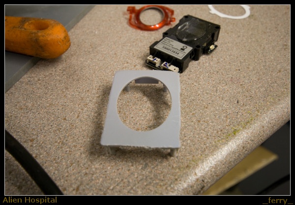
Hmm, a fingerprint reader, usefull ;)
Before mounting the fingerprint reader i roughly cut the hole for the display. After that i was able to determinate the exact size and position of the display and his cutout.
And the rear side. The base will be mounted on this part, but i'm still thinking about the design of it. And maybe i should add another instrument beneath the monitor, i have the space anyway. A defibrillator would be cool :D
A cutout with some mesh and styrene. The grey case is just rough. All the details like this will be done with styrene.
A fan in a monitor? Yes, i don't know if i need it, but you would hardly hear him at 5volt, and there will be more electronics (which produce heat) in the case compared to the original one. Just to be sure :)
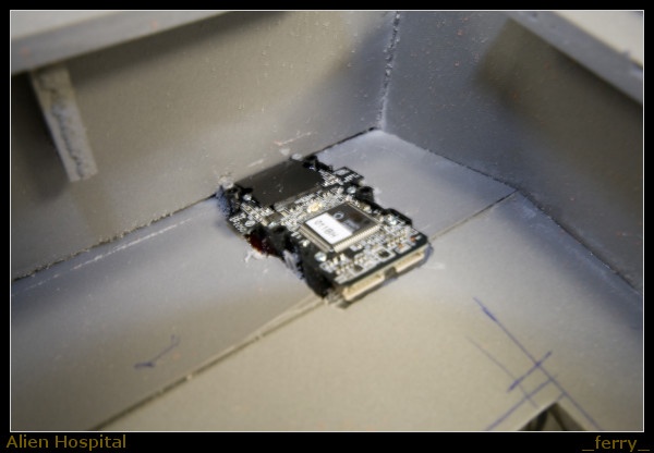
back to the reader, still recognize him? I had to remove a lot of material to be able to fit it inside. There was hardly a way to fit it with screws so i went to the dremel and took the click-n-hold part apart of the rest of his casing.
After cutting a very precisious hole (less than mm was enough to create a gap between finger print reader and the case) i was able to fit the PCB.
And this is how it looks at the front. There is plenty of space left for buttons, led's, connectors etc.
See :) I kept the shape exactly the same as the airhole at the rear, with those 45degree corners. (There was no other way to cut him out either hehe)
That looks pretty damn fine. Have some Repage
What more can I say? Speechless.
-Dave
wow, just wow!
I think we must find a new smiler for speachless. Like a mouth falling down or something. Well, that's how I feel right now: you're a master!!!
We're not worthy, We're not worthy!! Man this is so cool. The attention to detail is insane. +rep
Dude,... your good. Oh yea.
Thank all, the feedback was a good support for me to make some further progress on the monitor yesterday and today. :D
I've finished all the corners with some bondo. And sanded them down so the edges are now smooth and not sharp anymore.
It's time for a sleep, so i'm not going to upload pictures etc.
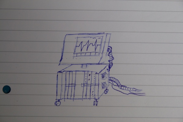
But here's a quick sketch to show you how my plan is:
On top you see the monitor. (duhh). IMHO it would be very empty to put only a monitor next to the operation table, so beneath the monitor there's a computer. Well, not a real one, but just a few snap-in prints. Hard to explain, wait for the photo's of the parts i mean.... I already found those parts at work. They have fancy switches and leds to blink on and off.
It's not just blinking leds, I can use the internal space as the external casing for my DVD writer and flashcard reader.
i was just wonderin if i could be u?
jk the mod is sweeet
+rep ;)
Hehe, well, if you're in the neighborhood you can always have a beer and have a modding session in my garage hehe. ;)Quote:
Originally Posted by lukeisthecoolest
Swheeeeeeet :D
Here are the pictures i had made a few days ago:
It's like he's having 2 drooly looking eyes now hehe.
A mounting support for the monitor
Every gap was filled with some bondo, and sanded down afterwards.
And the edges were smoothened, no sharp edges anymore :)
makes me think of...
It must be a apple engineer who's stolen the design from my alien mod! ;)
These are the parts i mentioned before. If anywone cares where they came from: I'm a service engineer for a company who produces climate and substrate computers/controllers for greenhouses. These are modules from such a computer..... 30 years ago.
I'll remove the mounted PCB's and add a microcontroller to switch the led's on and off. I could make those strips out of aluminium myself, but this saves a lot of time, is more detailed, including text, and has a lower price.
Yeah FREESTYLE modding :)Quote:
Originally Posted by _ferry_
Just joined this post, lovin it. Great work coming from your mill, never seen ANYTHING like that tiny syringe. Looking forward to more! +REP :banana:
Niiiiiiiiiiiiiiiiiiiiiiceeeeeeeeeeeee.
Yet another Sunday evening update:
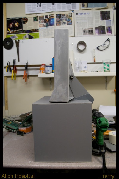
I spend some time on the machine beneath the monitor. Offcourse it needed a case, so i started with that:
Nothing special, just a box with the same width as the monitor.
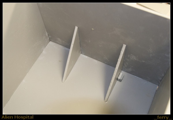
So let's build a arm which can hold up the monitor (+/- 5KG).
The block on the lower part will fit into a hole, so in fact the arm could even hold the monitor without any glue, because it hangs in this hole. I really need that, due to the weight of the monitor.
See :) I added another part next to it, looks better than just 1 sheet of plastic.
testfit, as you see it's possible to flip the monitor.
Between the 2 arms i added another reinforcement to prevent the monitor from swinging from left to right.
And 2 triangles on the inside so it won't hang over.
Back on the front, where these fronts will be mounted. As you can see i have a gap above it. Not an accident, I was thinking about filling that with iluminated acrylic. But later i decided it would be too fancy/useless. So it will be plastic. I need that space for mounting purposes anyway.
Testing the arm.
A tube for guiding the cables from case to tft (power, video, buttons, speakers etc. hope they'll fit :P )
Base painting the parts.
While drying i started with the buttons:
Imaging the time it takes to make this...
.... And double it, because i was not satisfied with the lower one, because it has some small misalignment.
I have 8 of these 7x5 dot matrix segments. They might be cool, but i think i can better save them for a usefull function on the real computer case, because this instument has a 12" TFT anyway. Don't know what to show on it either.
Found some cool connectors with locking ring as well.
Finally a picture of me while modding ;) The reason for not seeing that to often is that my camera is quite heavy and i always forget taking pictures.
The cutout, together with acrylic for the buttons and the top of it.
The plan for the buttons:
- 4 acrylic touch-sensitive buttons.
- each one with a small logo showing the function of it.
- When switched on, a led slowly fades on and illuminates the logo.
Suggestions needed:
Beneath the button there must be a small antenna, I was thinking about adding meshX panel for that, and beneath that another sheet of acryl with led's as a way of "backlite". Not shure which led colors to use, any ideas? Generally I'll use green, so what about green backlite and a red logo when switched on?
Function of the buttons:
Power to tft
Power to PC
blinking led's on machine on/off ( for when the PC is on and i want to sleep....)
...... Free function...
Shall i use commonly used icon's for that? And what to do with the last button? I could use it as a Mute function for the speakers.
Note that the operation table/pc will have his own buttons (plenty of them :D ) for led's and fan's.
For those who don't understand the button's, this is the view from top to bottom:
acryl with logo - MeshX as antenna - acrylic backlite - paint to prevent seeing trough.
You know, now i just have to hate you...
Maybe its having a kickass monitor frame, realistic looking tools made from scrap, or just the fact you can use a dremel with one hand, a camera with another and still manage to get perfect edges and a nicely focused picture.
Insane man. Great job!:)
I couldn't sleep yesterday because my mind wasthinking thinking about the buttons. But i have a new and better idea for it:
Combining the buttons on the left with the dot-matrix on the right, with some darkened acrylic on top of it.
I'll have a 2 matrixes beyond each button, making it a 10x7 dots display, good enough to create the symbol and have some nice small animations. Like a powersymbol which rotates around his midpoint, a blink effectb when touching the button, different symbol when switched off etc.
I'll might need to use a microcontroller for each button, maybe for 2 buttons but whatever, they'd cost me 1,75. :glasses:
I remember when I was trying to develop buttons for the TIP-3000. I went through so many ideas, before giving up and buying off the shelf parts.
Hardest parts for me are designing buttons and making hinges. (for doors)
-Dave
So true, but i do't mather about the time it takes to build this case, so that's why 'm trying to build the things myself, and touch buttons are very attractive, especially combined with a led display in them :)
Well, i managed to start building the dot matrix circuit, existing of a pic 16f628 and a 4017 IC to select the row so that the pic can send his 7 bits . The circuit is almost done, next step is to build a simpel test program, see if i can use 2 buttons on 1 microcontroller etc.
Finally someone else who uses PIC microcontrollers! Yeah, PIC's have veriable I/O pins so you can theoretically get tons of buttons on a single 8 pin PIC.Quote:
Well, i managed to start building the dot matrix circuit, existing of a pic 16f628 and a 4017 IC to select the row so that the pic can send his 7 bits . The circuit is almost done, next step is to build a simpel test program, see if i can use 2 buttons on 1 microcontroller etc.
Make me proud dude. :)
-Dave
Not a picture update this time... But a video update :D
I've created a cycling power symbol, gives you a idea how it looks like. This is just the first image. Once everything is done I can spend some time on creating nice animated logo's :)
saaaaaaaaaaaaaaaaaahhhhhhhhhhhhhhhhuuuuuuuuuuuuuuu eeeeeeeeeeeeeeeeeeeeeeeeeeeeeeeeeeeettttttttttttt
+repi think ill gonna rebuild this controller stuff 8)
I swear I give you way too many Reps dude, but how can I stop myself?
That is damn incredible.
-Dave
Thanks :D
And thanks for fixing the youtube link jdbnsn :) Thought i had to enter the full url, but that didn't work, now i know why, only the letter combination is necessary.
I've been watching this thread for a while, keeping quiet the whole time but I CAN'T KEEP QUIET!! HOW THE CRAP DID YOU DO THAT WITH YOUR BUTTON??? I WANNA LEARNNNNNNNNNNNNNNNNNN AHHHHHHHHHHHHH +5000rep for your homemade tools and the button:banana: :banana: :banana:
yeah give us the link for the circuits :D
Damn bro,... that power symbol thing is sweet.
Circuit drawning? I don't have one :DQuote:
Originally Posted by FrooP
It's just a bounch of transistors, resistors, a micro controller, many wires and an 4017 IC.
I can draw a schematic of it, but actually it's all about the microcontroller. The schematic diagram is just a microcontroller, sending a clock puls to the 4017 IC, and 10 times 7 bits of data (the horizontal line) to the led's
For a power symbol it's something like this:
0001000
0001000
0101010
1001001
1001001
1000001
0100010
0011100
0000000
0000000
Watch the 1'es and you'll see the symbol.
I've made really nice things with microcontrollers, a 8x8x8 led cube for example. Even while i don't even know all the difficult parts with reading and writing EEPROM data etc.
question....why dont you center the image?
Like this:
0000000
0001000
0001000
0101010
1001001
1001001
1000001
0100010
0011100
0000000
Jeaah, just a quick test...
And some suggested using a shorter vertical line, so i did by now, and so it's centered as well. Still writing the code, but now it's a continuous symbol, where led's go off and on from bottom to the top. Well you'll see in the next movie. Together with the "fingerprint scan line" ;)
I'm stil not 100% shure where to use the other 3 buttons for. I think 1 for opening the optical drive, 1 for lights on/off and 1 for switching the monitor off.
On the main case there will be touch buttons as well. For selecting fan speed, and switching various lights on and off. But those will might be made with 7-digits displays (0-9) instead of dot matrixes, because i have to keep those buttons smaller.