Thanks, that was informative, especially on the dangers.. I wasn't really told about these when I learned the process.. I was told: "see that yellow line on the floor? someone used a metal pan, it got etched too and then he ran with the pan outside.. " as a warning that FeCl is a bad thing that stains ;)Quote:
Originally Posted by simon275
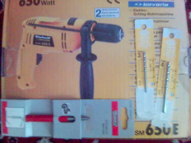
About my circuit: I don't have a laser printer, nor transfer paper. I used photoshop to make a smaller version of a print screen of the program I am using (layout plus, not free, almost infringing on the professional side, part of a very complex package of electronics testing and making program. got it from school, and just for educational purposes, so I don't have all features.. e.g. can't make my own components>limited, foot prints and stuff) and mirrored it on paper. After making the paper mask (cut black lines with sharp blade), I used a black marker to trace the circuit... Here is where I f-ed up a bit: I forgot a line or two in the process and also miss-aligned some components. The board is semi-functional as I've lost one of the output stages.. D'Oh! But I did get my led fired up and it is always on, as expected, and I can power one fan, with minor (really minor) speed adjustments. I had to drill the holes, solder the components then redrill some other holes.. I kinda messed up, but one thing did happen: I learned. What? The timing circuit is getting really hot after extended usage and it shouldn't. The utility I used to make the circuit wasn't very precise at estimating heat output, as it was running in a tweaked and skewed mode to allow for the pulses to be correctly interpreted.. usually, a jump from 0V to 12V is seen as a "convergence error" and you have to loosen the precise nature of the math part... So, I am back to the drawing board.. and gonna put more protections and safety measures on the board.. I wish I had an oscilloscope to see if I nailed the signal shape.. My multimeter can't tell me much in that area... So, long rant.. this is more of an electronic forum material, but as it is a fan controller, I will put this in from time to time..
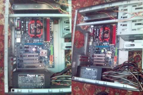
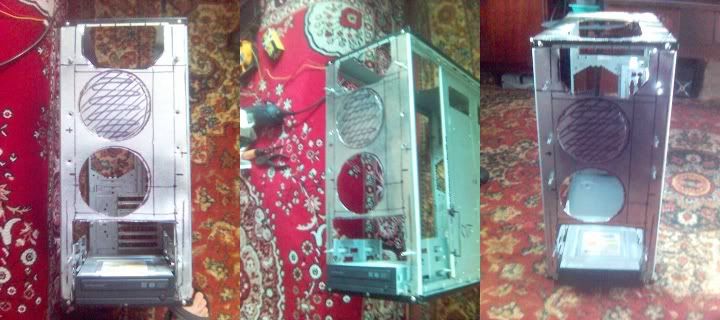
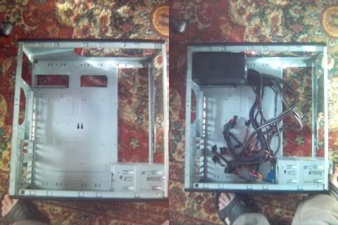
On the side of the real mod: Can anyone help me with the following?
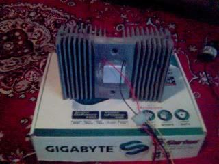
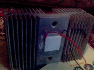
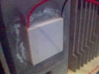
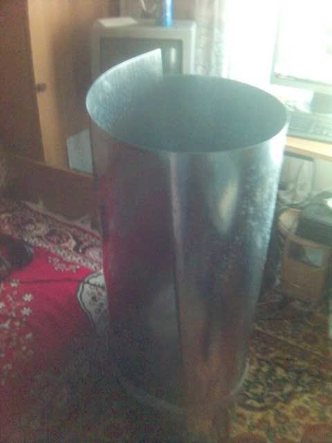
I plan on using a peltier to cool the liquid in my water cooling loop by using a low-flow, low-restriction in-line block mounted on a big chunk of aluminum, running on the side of the case (the back of the pc, behind the mobo), as big as possible.. This will make my PC heavier, but I can leave with that.. I don't plan on giving too much juice to the peltier so as not tho freeze the liquid.. but I was wondering how to calculate the temperature differential that will be created.. I'm gonna dome some 3d mocking later.. (I'm sick as hell right now.. my nose is like a bunch of slugs having a party, if that's possible, and my eyes are like disco balls.. can't even model without messing up.. darn flu..)
I would have: loop=|waterblock|peltier|huge_radiator The water coming out of the cooled waterblock would go straight into the cpu block and then to other components.. Then into the radiators and finally back to the cooled waterblock. Is this a good idea from your experience?
Gonna go eat some hot soup.. bye..