-
My RepRap Build. (3d printer for those not in the know)
I haven't made anything in a few months now. The last thing I made was the Coil Gun which took all of 3 hours to actually build and the novelty wore off in about 15 min. So I had an itch to build something. Something big. I was debating on an actual scratch build case mod, but could not justify it because I have no need for a new computer right now.
I first learned about the RepRap project via Hackaday about a year and a half ago. I immediately wanted to jump in feet first, but things were still very buggy and the longevity of the extrusion head was very short. So I sat back and contributed a few ideas here and there, did some technical drawings of stuff that was missing and mostly just sat back and watched the progress unfold. This brings us to this month.
I had not been on the reprap site in about 2 months. So with nothing to do on a Saturday afternoon I browsed the site for a few hours. Things had made leaps and bounds. There were completely new electronics that were more powerful and reliable, the extrusion head was completely redesigned to what I always thought would be a better design. The software was even refined. There were people getting printing resolutions of less than 0.1mm. I decided to go ahead and build me a RepRap.
But first I have to build what is known as a RepStrap. This is a Cartesian bot that will allow me to print the parts I need to make a more accurate and faster Darwin RepRap. This is not a necessary step as I could just buy all the parts laser cut from acrylic from a few places,[url=http://Ponoko.com]Ponoko[url] or bits from bytes and just have to supply a few mechanical parts and electronics or I could buy a ready made reprap derived 3d printer CupCake CNC. But there is no fun in that. It works great for people who are not mechanically inclined or have no tools and workspace.
So on with the work log.
This post will serve as my main build log. I will be posting all of the build updates here. I will from time to time post some small updates or thoughts on my new site. (still under construction) The Maker's Workbench
-
Re: My RepRap Build. (3d printer for those not in the know)
There are many different RepStrap designs. I chose the easiest and most often built RepRap Seedling. AKA McWire Cartesian Bot v1.2 Its named McWire after the original designer.
Quote:
Originally Posted by reprap.org
This design is based on a previous design by Tom McGuire, and was named after him. We have since taken his design and improved upon it in a few crucial areas and adapted it for our particular needs. We are very grateful and appreciate the hard work he put in. All of our subsequent work is released under the GPL.
My goal are to take the first step and build this.
http://farm4.static.flickr.com/3132/...c3a678.jpg?v=0
and use it to eventually build this
and I will use it to print things like these
Corner Brackets
Gears
Parts for another RepRap
Sandals (yea I know)
Statues
Lego like bricks
Cool looking screw top boxes
It is tradition for your first print to be a shot glass. You then use that shot glass to toast your machine.
and even other RepRaps
With this machine I can print anything that can be designed in 3D within the machines physical limitations. I can print custom reservoirs for water cooling, fan grills,custom drive covers, whole case faces, hhd enclosures, fan shrouds to duct air, pen bodies, tweezers, combs, flashlights, there are hundreds of thousands of things I can print. Besides how cool will it be to print stuff in the 3rd dimension?
All the above images are courtesy http://reprap.org and its contributors, http://thingverse.com and its contributors.
-
Re: My RepRap Build. (3d printer for those not in the know)
sweet :bowdown: I'm checkin this out!
-
Re: My RepRap Build. (3d printer for those not in the know)
So today I ordered all of the parts needed for the McWire from McMaster-Carr, and home depot. Total came out to $98.75. Now I need to source parts for an extruder. I would prefer a pinch wheel from printed parts but if I can find an old design one used for a good price I will buy it.
I also bought the plexi for the axes stages and the bearing arms. I got it as scrap from a local glass shop for $12. Its 5mm clear. This weekend I need to head to harbor freight and pick up a 82 degree countersink. I have a spare PSU from an old atx case. I still have a few of the electronic parts to order. I need to find a flat surface hotplate so I can reflow the solder paste I have to use when I populate the electronics boards. They are surface mount. I have done reflow work before with a hotplate so this will not be new.
I plan on using a full tower pc case so I can fit all of the electronics including the host PC inside. I might be doing the first RepRap related case mod. PC plans are 2+ghz athlon x2, 4gb ram, cheap mobo with onboard video. It will more than likely have Ubuntu installed on it because open source stuff is awesome. IMO Open source software is the only way to go when planning a open source project like building a RepRap
I have linked to a google spread sheet below of the parts list and cost so far.
http://spreadsheets.google.com/pub?k...=0&output=html
-
Re: My RepRap Build. (3d printer for those not in the know)
-
Re: My RepRap Build. (3d printer for those not in the know)
Well the order from McMaster-Carr will be here in a few hours. That's less than 24 hours from the order date. It helps that McMaster-Carr has a warehouse less than 3 hours from my house and after the FedEx pickup it had less than 2.5 hours to travel to my local FedEx hub.
So tonight I hope to get the base of the McWire put together. Thats the iron pipe that forms the base and upright that will hold the z axis. I put in an order for some solder paste this morning and a needle to put it on the boards. I now need to find a flat surface hotplate. Wal-mart is supposed to have one for $12
Note to self: Still need:
- 3 NEMA 23 8 wire stepper motors Here
- Extrusion head
- 16 skate bearings (608) Here
- Thermocouple temp sensor kit Here
- 6' Nichrom Wire Here
- RJ45 connectors and boots
- USBtinyISP AVR Programmer Kit Here
- 3mm plastic filament hdpe, abs, pla, etc. (what you print with) Here I can get it much cheaper (20-30%) from other sources.
I also want to note that I hope to be printing by the end of the year. I think I will be printing much faster but my goal is to print a shot glass by december 31st.
-
Re: My RepRap Build. (3d printer for those not in the know)
These things are amazing. I'm a huge fan of anything CNC and these take that to the next level. I plan to build and document a router when I get my mod shop up and running. Can't wait to see more of this.
-CollinstheClown
-
Re: My RepRap Build. (3d printer for those not in the know)
There are already people turning their darwin repraps into cnc routers using dremels as the power head. The workable area is small but its a step in the right direction and proof that the reprap electronics can handle milling and routing.
-
Re: My RepRap Build. (3d printer for those not in the know)
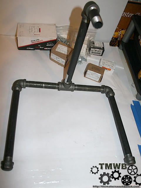
And the build has started.
FexEx delivered my hardware and raw materials around 6:24. That was exactly 29 hours from the time I placed my order. What they lack in proper ordering etiquette they make up for in shipping time. They packed 19lbs into a 24"x14"x6" box that was held together with paper tape. The fedex guy apologized for the rattling noise in the box and told me that the bottom had busted on the box when they were loading it onto the truck. He said that they had put everything back in the box. During transit to my home a box of 5/16" nuts busted open and were loose in the box. Luckily they were all still there.
I also created a new logo to brand my photos with. I will be posting a full build log in blog format on my new site. http://themakersworkbench.com So what do you think about the logo?
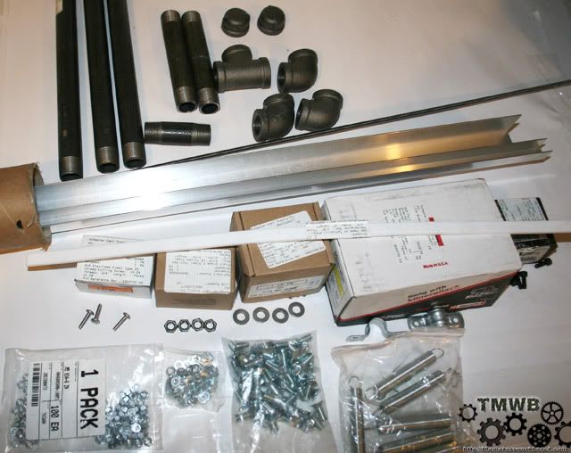
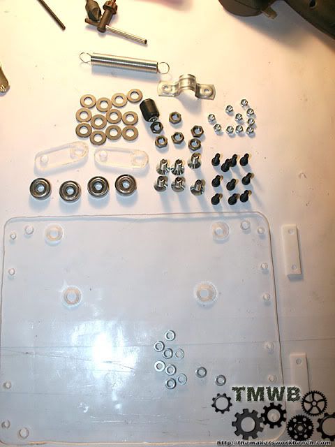
So how about some pics of the goodies?
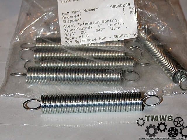
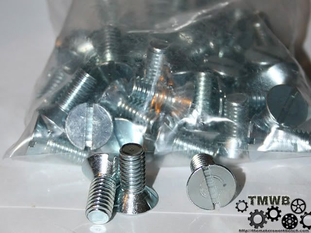
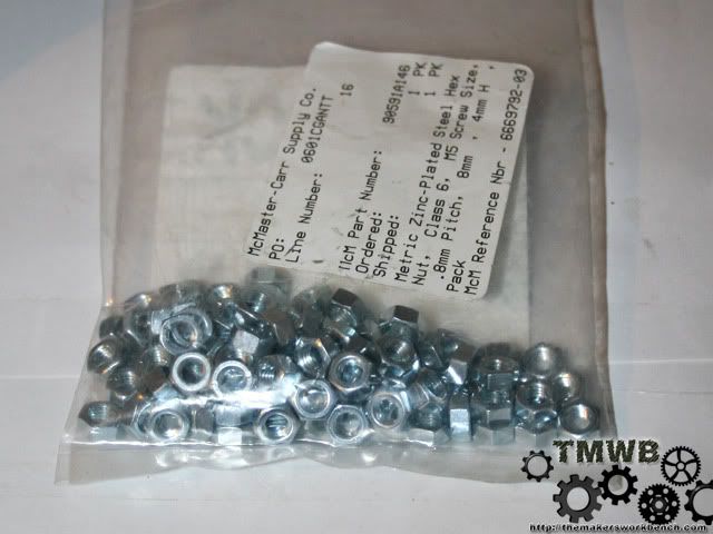
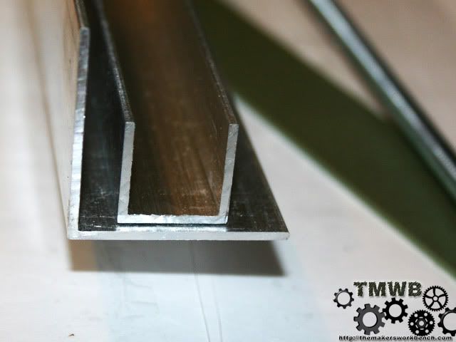
Lets start with a pic of everything. I want to point out the 24" x 1/2"x1/4" bar of ptfe (teflon) the 1/4-20 6' long threaded rod, 8' 1 1/2" x 1 1/2" aluminum angle and 8' 3/4" x 3/4" aluminum U channel. The rest is screws, bolts, nuts, washers, pipe clamps, springs, etc.
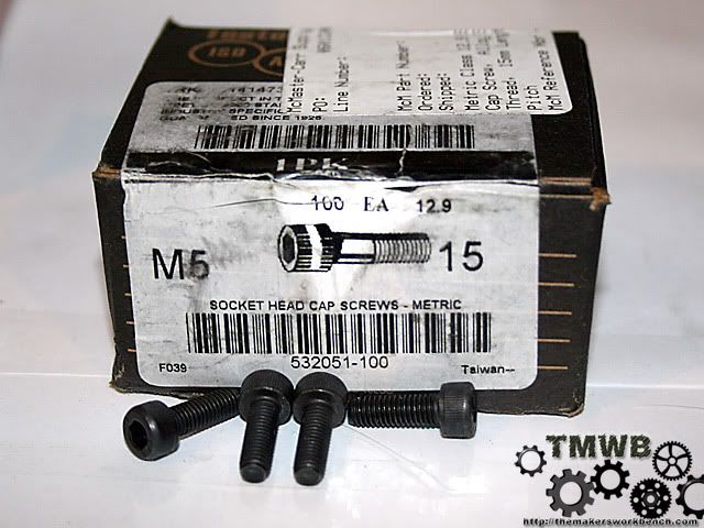
These are the M5 cap screws
4" 4.75lb extension springs. These will hold tension on the bearing arms.
The 5/16" flat head machine screws. These will hold everything onto the stages.
Nuts for the M5 Cap screws
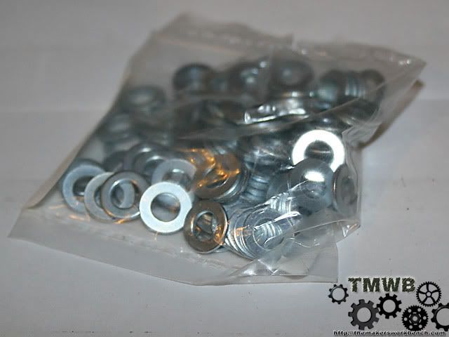
Washers for the M5 Cap screws
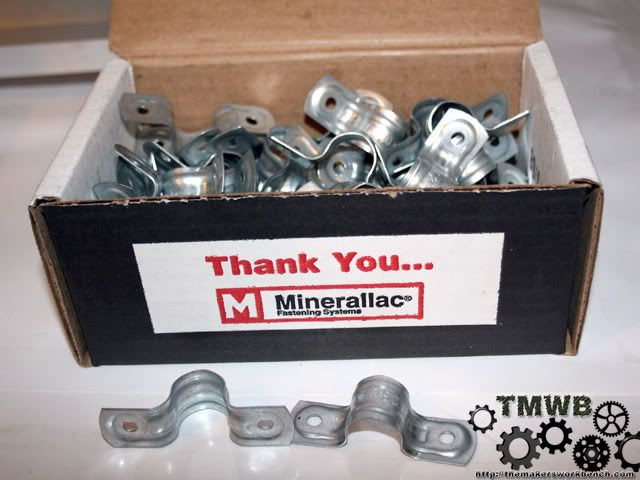
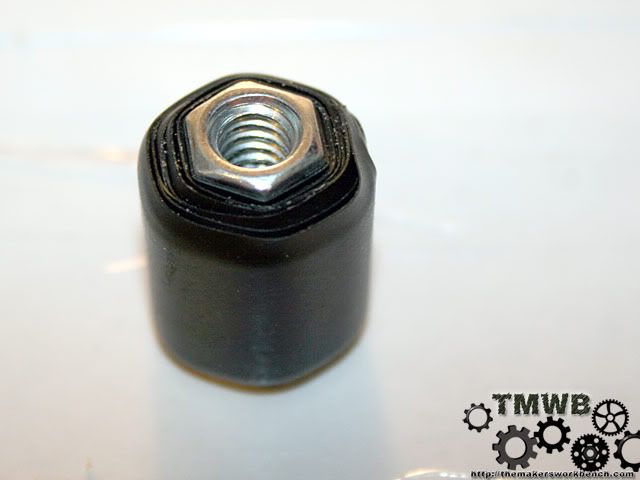
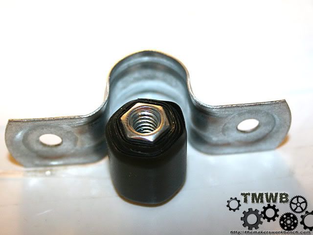
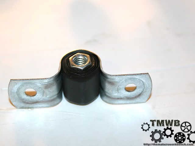
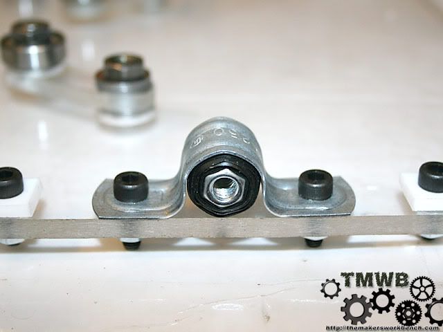
These are 2 hole conduit clamps. They will hold a bearing which will support the other end of the lead screws. I had to buy 50 but only need 3.
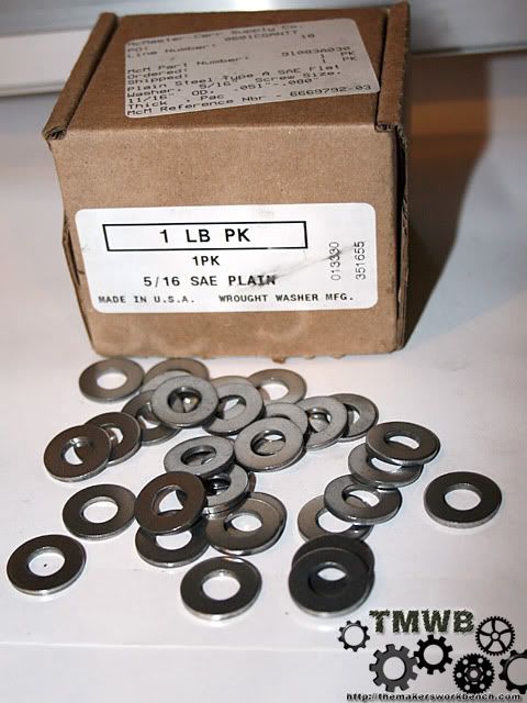
Washers for the 5/16 machine screws. Once again I only needed about 40 but it was cheaper to buy 1lb (192 pieces)
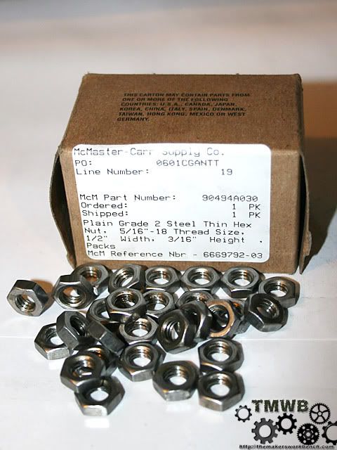
Nuts for the 5/16 machine screws. Same deal only need about 40 but was cheaper to buy 100.
10-24 3/4" long self threading screws. Needed about 18 and was cheaper to buy 50.
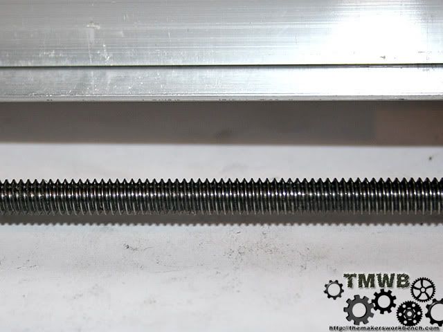
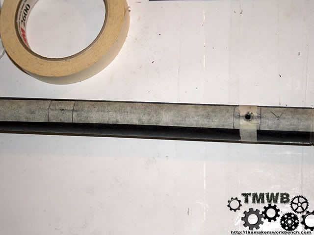
small image of a section of the 1/4"-20 threaded rod. I ordered stainless steel but they sent plain steel. Charged me for plain steel too. This will work fine but may wear faster.
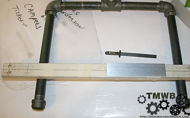
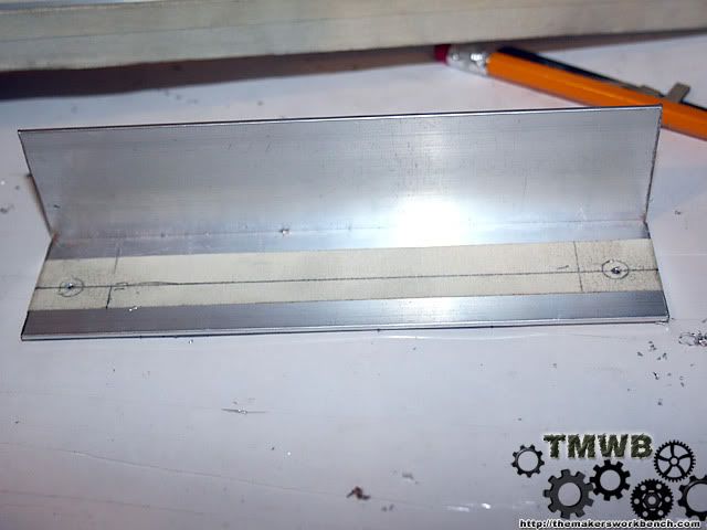
This is 2 major pieces of the McWire build. The 1 1/2" x 1 1/2' X 1/8" aluminum angle and 3/4"x3/4"x1/8" aluminum U channel. Both pieces are 8' long.
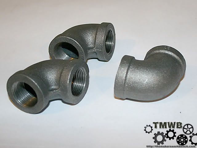
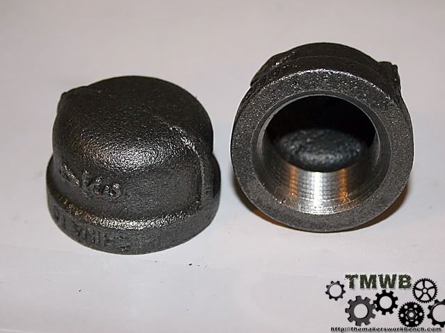
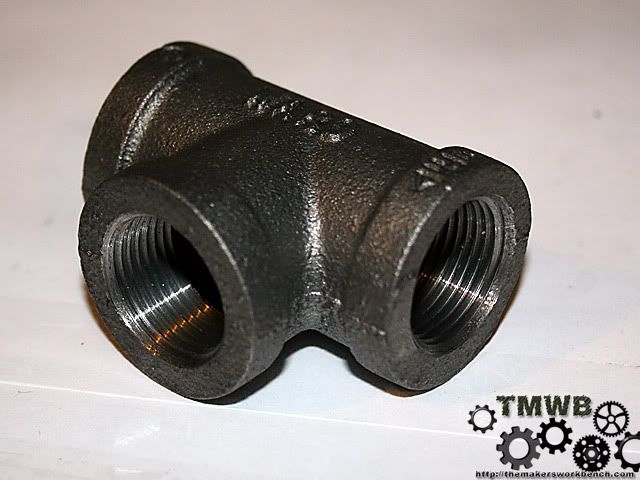
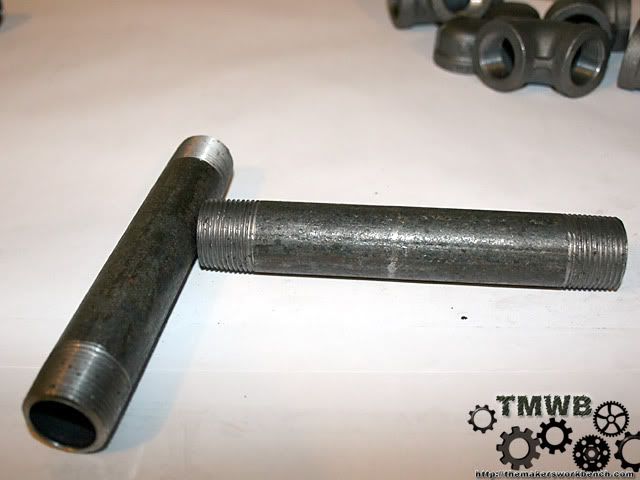
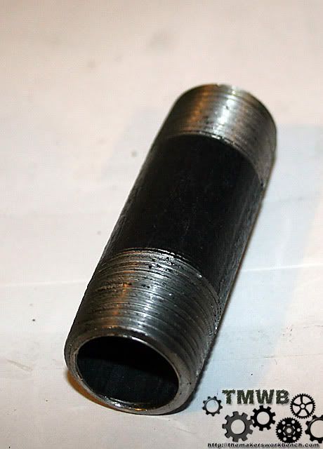
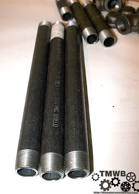
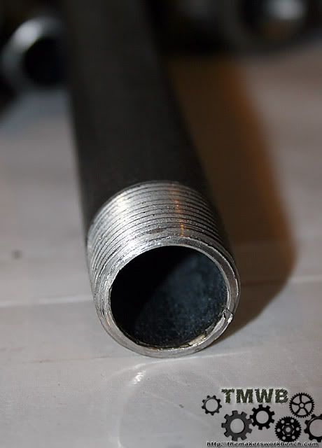
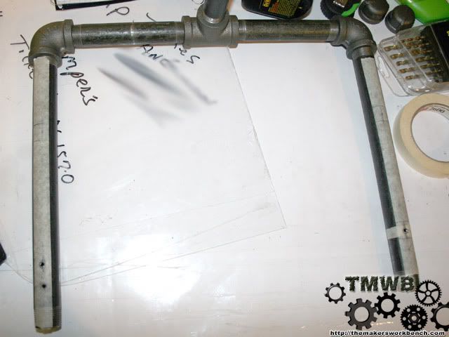
Now we are getting into the parts that make up the base. These are all black iron sch40 pipe. These parts will eventually form the "frame" that holds the moving parts in place.
The 90 degree elbows
End Caps
T fitting
6" x 3/4" nipple
3"x3/4" nipple
12"x3/4" nipple
Just a single shot of one of the pipes
And all the pipes loosely fit for fun.
Here is a link to the invoice from McMaster if your wondering about price.
http://i152.photobucket.com/albums/s...ster-order.gif
-
Re: My RepRap Build. (3d printer for those not in the know)
Man, you are really taking on a cool project here. I've been thinking about building a cnc router in the fall. but nothing this extreme. I really hope you get this to work. Please make sure you keep us updated on your progress.
+rep. for sure!
-
Re: My RepRap Build. (3d printer for those not in the know)
yeah man this is sweet keep it up
-
Re: My RepRap Build. (3d printer for those not in the know)
Thanks guys.
I have no doubt that I will get it to work. The R&D side of the RepRap project has produced reliable stuff in the past few months. There are over 1000 reprap derived printers out there now and they are all singling that sweet stepper motor tune. I think the second thing I am going to print is the TBCS logo and mail it to Jon or give it away in a contest.
-
Re: My RepRap Build. (3d printer for those not in the know)
Quote:
Originally Posted by
rendermandan

Man, you are really taking on a cool project here.
No. . Kiddin' This is really going to be neat. +Rep
I have seen the homemade cnc machines but never a 3D Printer.
Can't wait to see this bad boy in action. :up::up:
-
Re: My RepRap Build. (3d printer for those not in the know)
I was telling a friend about this over lunch today and he pointed out the fact that I could just mount a dremel to it like others are doing and mill out the acrylic parts for the plastic extrusion head. Why this never occurred to me I do not know.
I am bidding on some skate bearings on ebay but I think I might be outbid because my max bid is $4.00 for 8. I am still trying to source a 82 degree counter sink locally. It seems that every where I call thinks a counter sink is a counter sink. a 1 size fits all type deal. I even called a tool and die shop and they thought I was talking about a step drill. McMaster has one but its over prices by a lot.
I hope to cut the x axis rails tonight and the angle support for it. I also need to go buy some jigsaw blades to cut the acrylic. Anyone have some suggestions on what tooth count to get?
-
Re: My RepRap Build. (3d printer for those not in the know)
I got the x rails and angle cut last night. Haven't drilled any holes yet because there are inconsistencies in the build constructions on the reprap site. Instead of publishing a simple technical drawing of the hole placements they thought it would be good to dumb it down to the point of printing the hole locations onto a sticker sheet and have you print it out and attach it to the rail then drill. The problem is that the sticker holes have not worked for anyone.
I am going to do this the hard way it looks like. Time to open up autocad and get to work.
-
Re: My RepRap Build. (3d printer for those not in the know)
yay for auto cad and yay for reprap.
plus rep to you sir.
badoom tshh!
Will the rapstrap become a miller then afterwards?
-
Re: My RepRap Build. (3d printer for those not in the know)
more than likely yes I am going to modify it into a cnc mill or router.
-
Re: My RepRap Build. (3d printer for those not in the know)
Today was kind of productive. After sorting through all of the documents and photos online of various McWire builds, and none of the measurements seemed to match up from build to build. To further complicate this problem no one seemed to post or have any technical drawing of hole placements, critical measurements, or even non critical measurements. What I did find was drawings meant to be printed on sticker sheet and then placed on the vairous metal components. This left too much room for error for my taste. I finally came to the conclusion that I was going to have to solve this problem once and for all. I will be creating all of the technical drawings as my build progresses.
After I got all of that sorted out I decided to get to work and cut some metal. Luckily the measurements for the X stage rails were available and I was able to start there. I didn't get a photo of them being cut because all I own is DSLRs and its hard to hold a dremel with one hand and a 3lb+ camera in the other and take a photo. The rails are cut from the 3/4" x 3/4" aluminum U channel. Cut them both to 21". Make the cuts as square as possible and file the edges to remove sharp burs.
The next things we needed to cut were 2 pieces of the 1 1/2" x 1 1/2" aluminum angle. These should be cut to 6 3/4". Cut these as square as possible. Again file the edges to remove any burrs.
Now that we have them cut lets drill some holes.
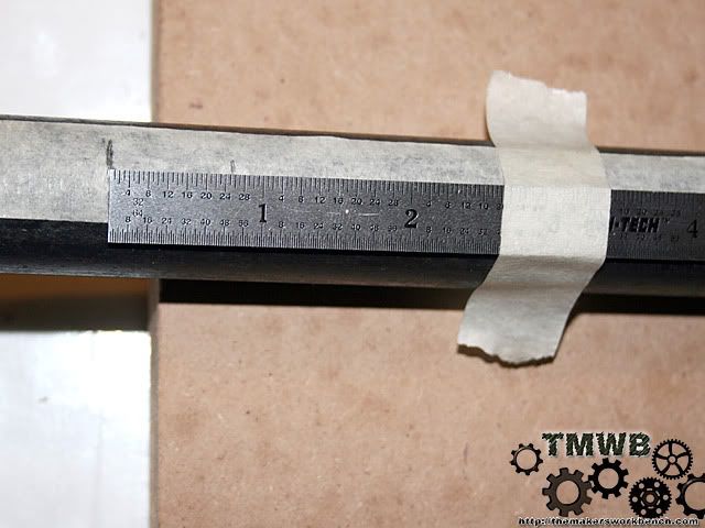
We will start with the 21" rails. Put a piece of tape along the bottom so you have something to mark on. Mark your first 2 holes 3/4 inch from each end. Drill on those marks with a 5/16" bit. I also have the second set of holes marked and pre drilled in this photo. Don't worry about them right now.
\
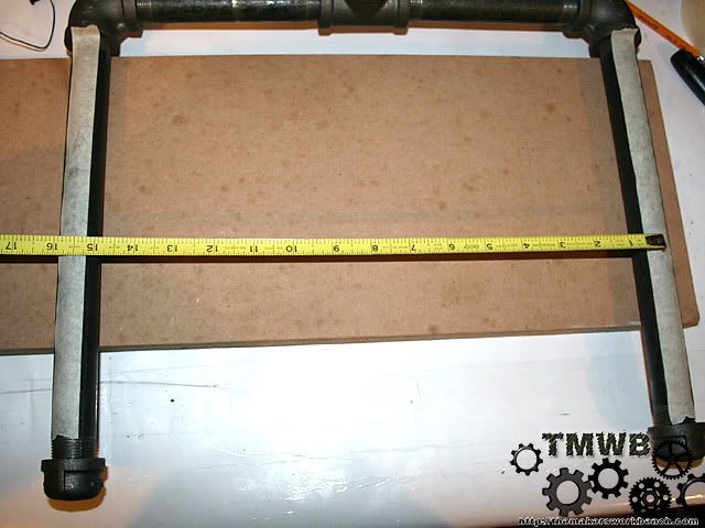
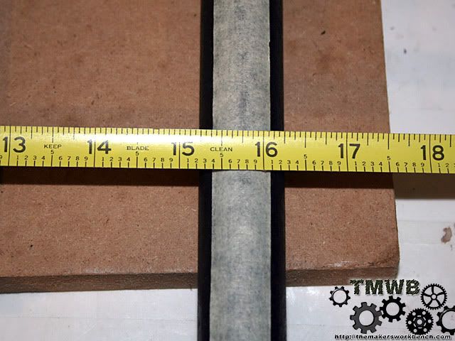
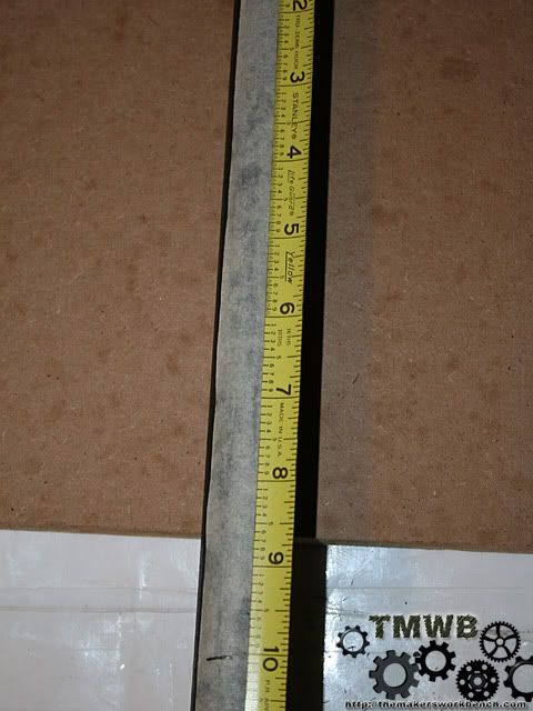
Now lets mark our holes for the screws we will use to attach the rails to the base. We need to center the rails on to the base. To do this we need to measure from the center of each leg of our base.
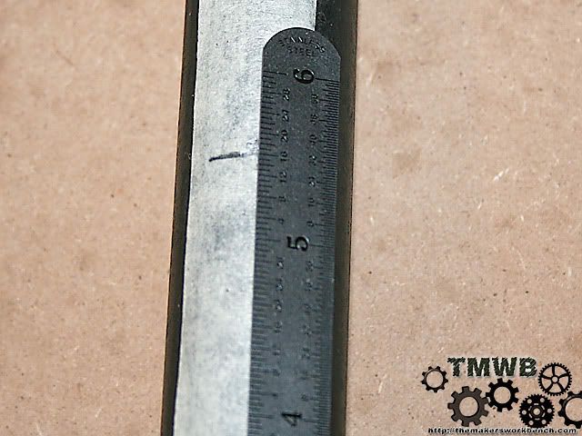
In our case this is 15 1/2". (The photo shows it as 15 3/4 because the taped moved just a bit when I took the photo.) This will vary from every build because of the nature of how far the pipes will thread into each other.
So we know that our rails are 21" long and our base is 15 1/2" wide. This leaves 5 1/2" so we will divide that by 2 and get 2 1/4. So we measure 2 1/4" from our rail ends and mark our holes. It is a good idea to tape the rails together and use a square to mark the line on both rails at once.This will make sure that the holes are in the exact same place on both rails.
Now drill a 5/64" pilot hole. (I chose 5/64" because I have a bag of 40 of them)
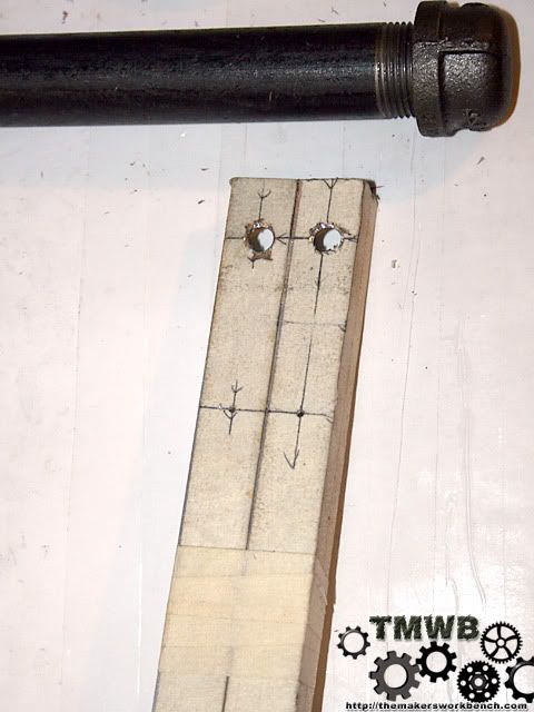
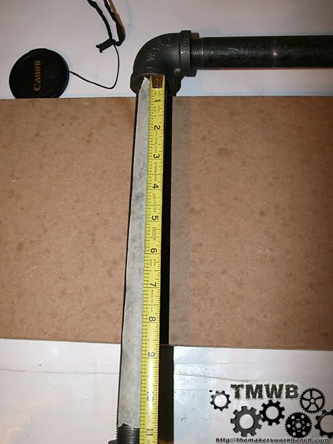
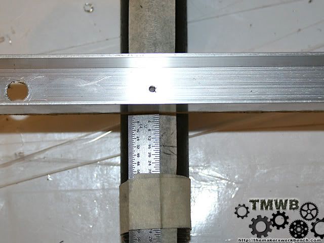
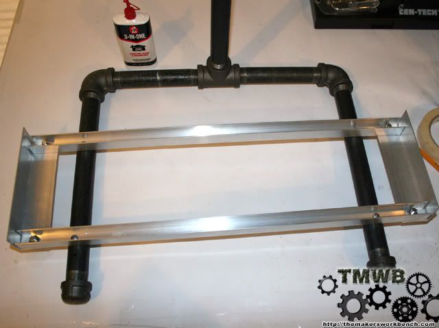
Now we are going to locate the position the rails need to mount onto the base. To do this I made a datum mark. This mark is the same on each side and gives me a solid point of reference so mark my rail locations. Using a tape measure, butt the end of the tape up against the 90degree elbow and mark 10" on your pipe. Do the same on the other side.
Now that we have a point of reference to work off of lets mark the placement of our rails.
Measure 13/16" off the datum mark place a mark.
Then off that mark measure an additional 5 9/16".
Now drill these hole marks with a pilot hole.
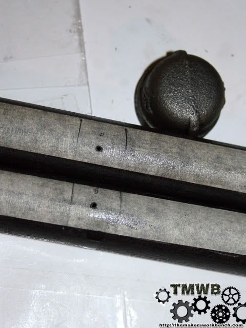
Ok lets make sure that everything lines up. Using the drill bit you drilled the pilot hole with place it in the hole in one of the rails. Ignore the angle on the end.
Now line up the other 2 holes. If they match up then great. If they do not match up you have made a mistake some where. (notice my image 2 down from this one.)
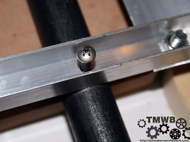
Now drill out the pilot holes with an 11/64" drill bit. This bit size is critical because these are the holes we will be screwing the self tapping 10-24 machine screws into.
Remember to measure twice and cut once or you get to do it all over again. Notice the extra hole at the bottom. I accidentally drilled out my datum mark. :(
Now drill out the pilot holes in the rails with the same drill bit.
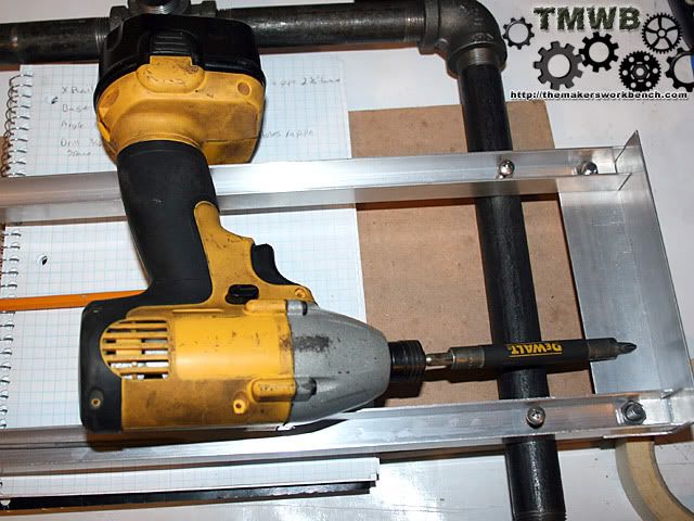
Then you can screw the rail to the base using the 10-24 self tapping machine screws. This will be a little hard to do by hand because the threads of the screws are actually cutting threads into the rails and pipe at the same time. I used my favorite cordless power tool in the world. A Dewalt 18volt cordless impact driver.
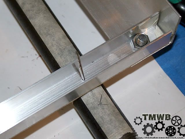
Now lets mark the hole placements in our angle we cut for the ends. Measure 1/2" from the sides and 3/4" from the end. This will give us a flush fit against the rails. Again drill pilot holes with a small bit.
Now drill out those holes with an 5/16 drill bit. Sorry I forgot to take a photo. Will add one later.
Now mount the angle to the ends of the rails using the 5/16" machine screws. (yes I know they are made for a countersunk hole but it doesn't matter that much. If you ordered them from McMaster like I did you got plenty to spare. Place the screw in from the bottom and put the nut inside the rail. Tighten them down and your finished with the x stage rails.
That's all I got to today. I am waiting on the 608 skate bearings to come in before I can continue. Next time we will be cutting and drilling some plexi. You can also follow this build and download all the photos and plans on my new site http://themakersworkbench.com.
-
Re: My RepRap Build. (3d printer for those not in the know)
Bravo! Bravo!!
This thing is coming out sweet, btw I finally finished drawing up plans for mine! yay, I got you renders I'll send them to you in e-mail.
-
Re: My RepRap Build. (3d printer for those not in the know)
Well I kinda put my foot in my mouth when I said that I would be creating a whole new set of technical drawings for this build. After spending a few hours this morning searching and emailing people for some simple measurements to start from I found nothing. Not 1 single measurement. So I am taking the easy route and printing the drill locations out.
Here is a link to the files on sourceforge if anyone wants to take a look at them.
http://downloads.sourceforge.net/rep...6&big_mirror=0
-
Re: My RepRap Build. (3d printer for those not in the know)
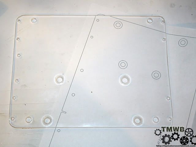
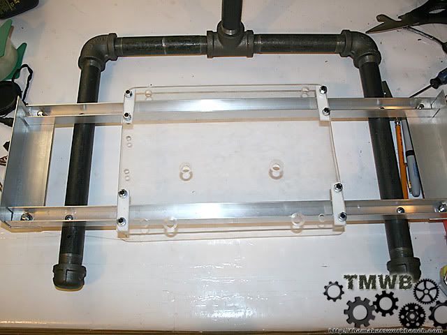
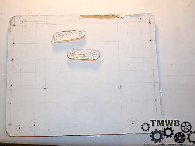
Small update. Yesterday I cut the plexi out for the X stage. I lost my jigsaw (i think it may have grew legs and walked off) so I did things the hard way and cut the x stage out with a hacksaw. The cut was a little crooked but I straightened it up with a drum sander. I did decide to go with the printed guides rather than trying to do it all from scratch. This was mainly due to lack of information that I needed to start the drawings.
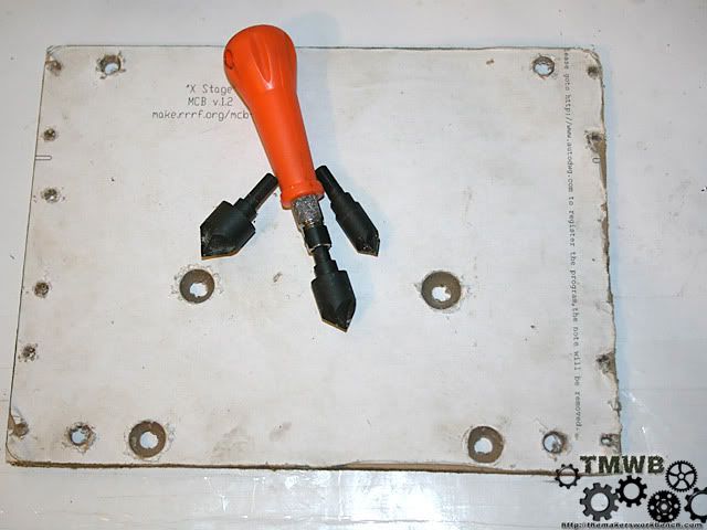
So I printed out the drill guide and glued it to the protective paper on the plexi, then cut it out.
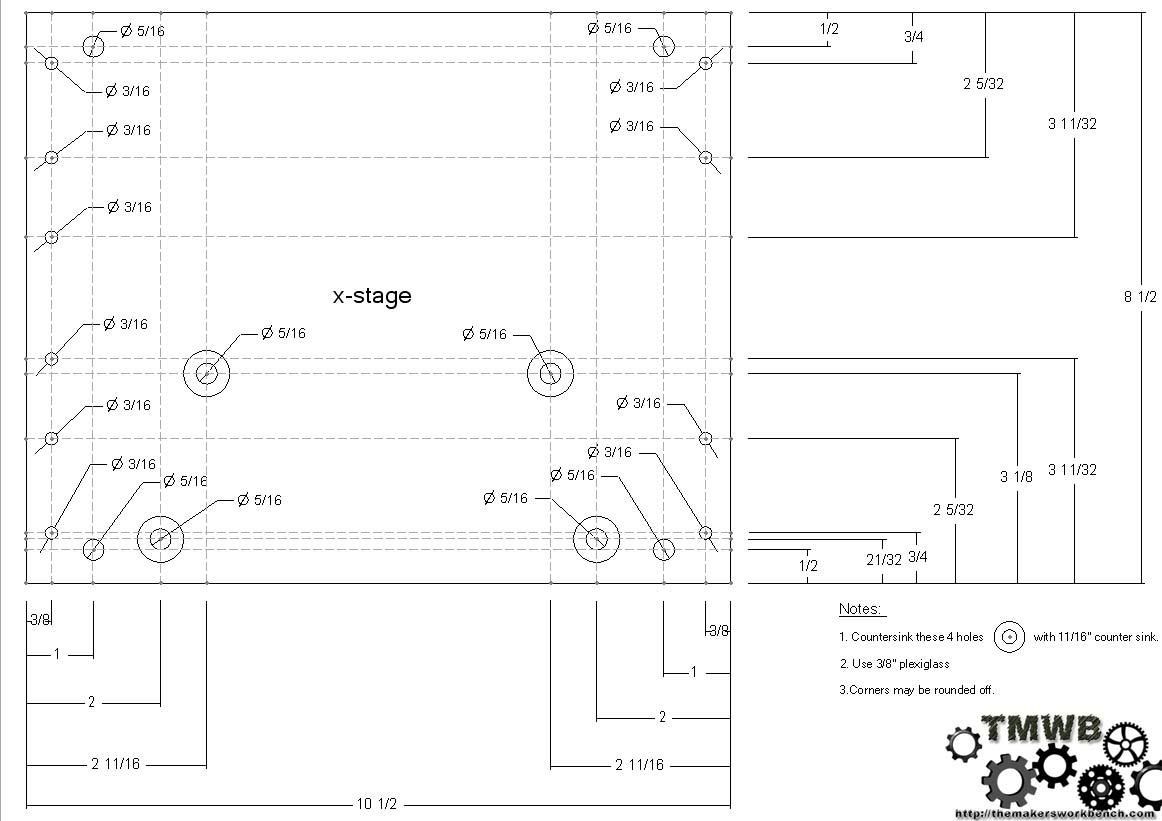
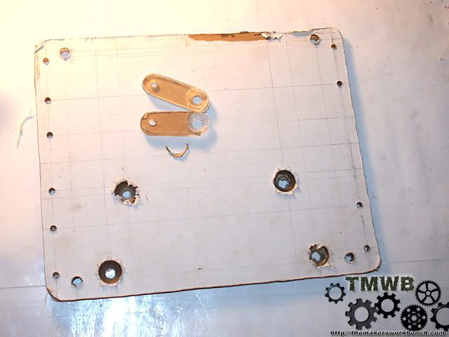
Next I drilled and counter sunk the holes. The counter sunk was done with an 11/16 bit and I stopped just shy of the full depth. This let the 5/8" flat head machine screws sit nice and flush. Note that I also drilled out the PTFE bearing mounting holes out to fit the M5 Cap screws. This made more sense than using the self tapping 10-24 screws.
Then I pulled the paper backing off and inspected my work. Everything looks great.
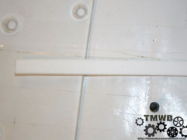
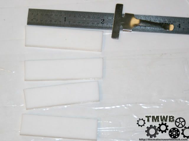
Now we need to cut 1/2" x 1/8" PTFE strip.
I cut these at roughly 2 inches long. We need 4 for the X stage. To cut them I used a ordinary box cutter.
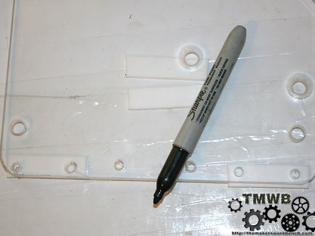
Now we need to mark the hole placements. This is easy to do by just laying them under the plexi and making a dot.
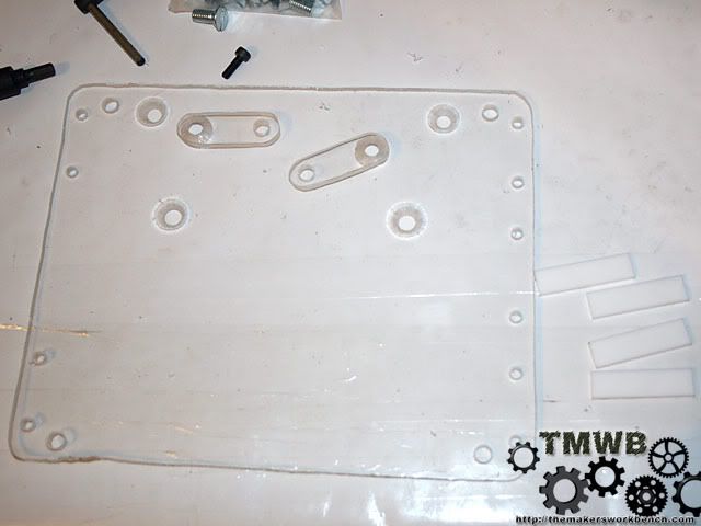
Then drill out the holes with a 13/64" drill bit. The same one we used to drill out the holes in the plexi. Grab 4 M5 cap screws, 4 M5 washers, and 4 M5 hex nuts.
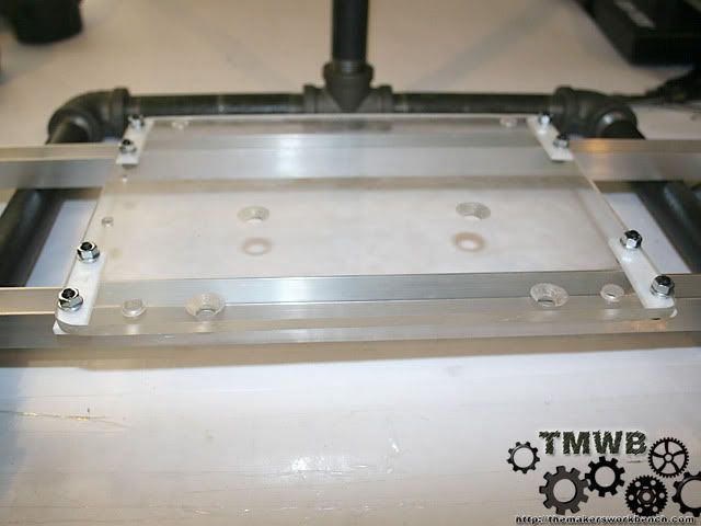
Now secure the PTFE bearings to the plexi with the M5 hardware.
Now place the x stage onto the rails. IF it fits right you should have a 1/16"- 1/8" gap between the M5 screw heads and the rails. A little more or little less wont hurt anything. What we are looking for is that nothing is binding. Move the stage all the way from one end of the rails to the other. In my case I had to elongate 1 of the M5 screw holes in my stage plexi and ptfe bearing about "1/32 of an inch. It was not binding but was too close for my taste.
I was hoping to include the skate bearings install in this update but UPS has not delivered them yet. I also need to go out to my shop and cut the bearing arms out on the band saw. So they will be saved for the next update.
-
Re: My RepRap Build. (3d printer for those not in the know)
-
Re: My RepRap Build. (3d printer for those not in the know)
Thanks man. I am still waiting on UPS to deliver my 608 size skate bearings. They finally admitted that they are lost. So who knows when I will get them.
-
Re: My RepRap Build. (3d printer for those not in the know)
Looks like your well under way on this. Keep it up!
-
Re: My RepRap Build. (3d printer for those not in the know)
-
Re: My RepRap Build. (3d printer for those not in the know)
lookin good man, cant wait to see it come together!
-
Re: My RepRap Build. (3d printer for those not in the know)
Thanks SXR.
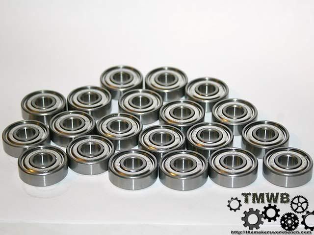
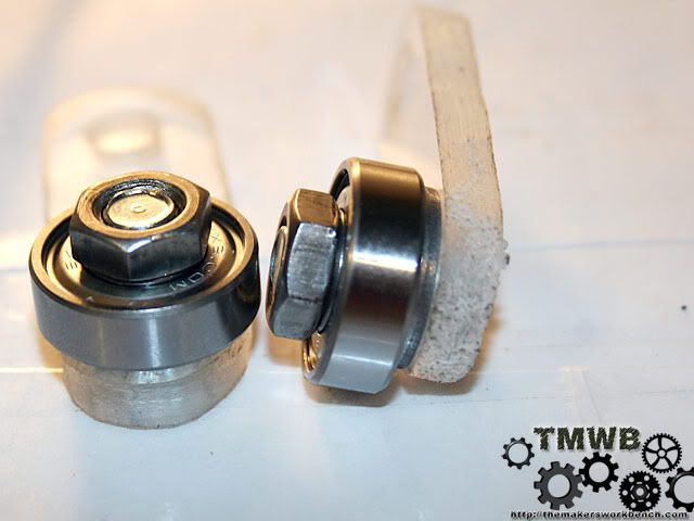
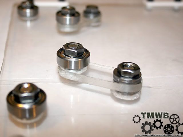
The bearings arrived today. A UPS manager delivered them in her personal car with an apology and told me that my shipping $$ will be refunded to the shipper and they will send it to me. I am happy and I have 32 608 sized skate bearings just waiting for projects.
-
Re: My RepRap Build. (3d printer for those not in the know)
Well thats badass!
-CollinstheClown
-
Re: My RepRap Build. (3d printer for those not in the know)
Thanks Collins
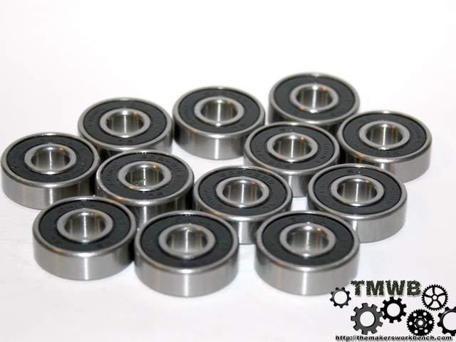
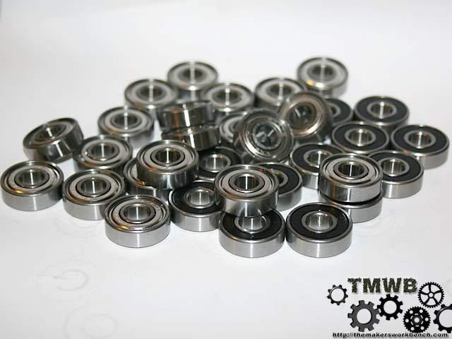
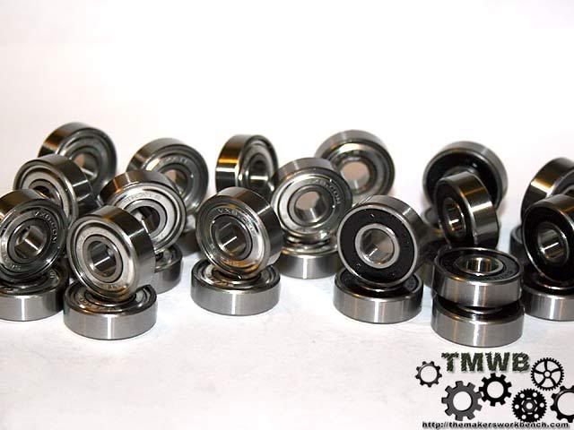
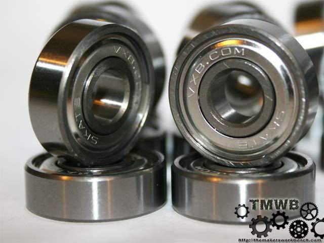
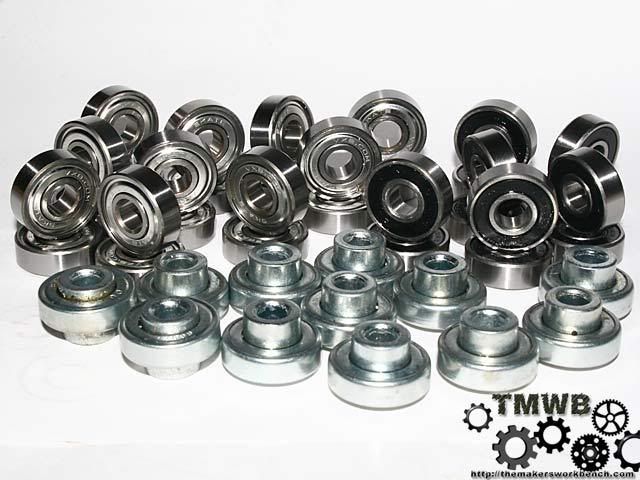
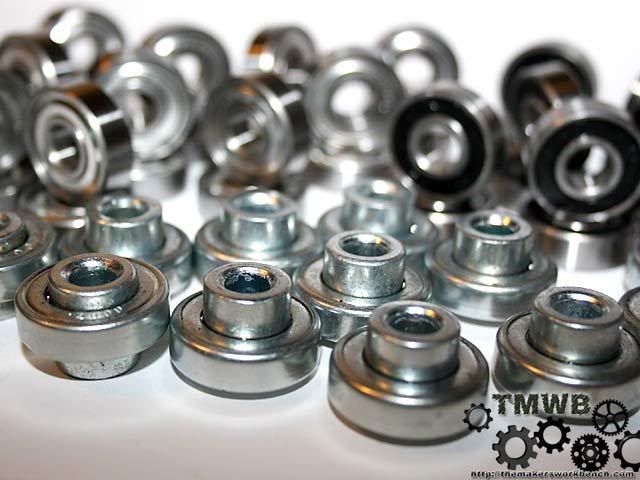
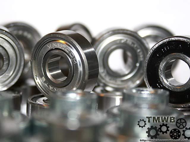
Time for photos...... Ok so I may have went overboard with the bearing photos... Enjoy
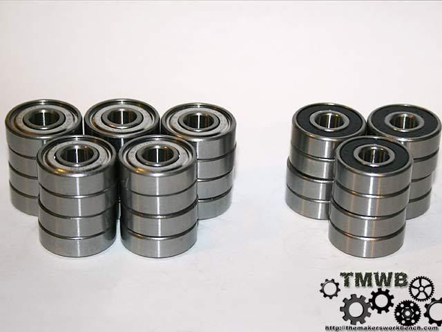
The ones with silver shields were ordered from VXB Bearings. The ones with black rubber shields were bought locally from a bike shop for $5. The ones with the large center were salvaged from an old pair of roller blades.
-
Re: My RepRap Build. (3d printer for those not in the know)
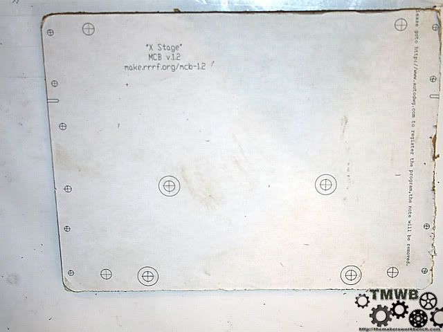
Well it seems I have hit a wall head on with the pedal on the floor. The reprap project recommends printing out the design of the x,y,z stages and gluing it to the plexi and using that as a cutting / drilling guide. The alternative is to buy the laser cut parts for about $100. It's literally $10 worth of plexi scrap from your local glass shop and straight cuts. The holes can easily be done with a hand drill or a drill press like I am using. It takes about 10 minutes to cut and drill the plexi per stage. So being a the cheap man I am, there is no way I could justify spending $100 on a total of about $10 and an hours worth of work. That is the reason I ran into problems. (well that and the fact that the build log / instructions for the reprap McWire are very unorganized and full of misinformation.)
This is where I ran into my first big problem. When researching for technical drawings of the X,Y,Z, stage drawings I never found anything. So I had no choice but to print the design out (as recommended by the reprap project) and glue it to the plexi. The problem with that is that the genius designer drew them to "fit" onto an 8.5" x 11" sheet of paper. Which is the standard sheet that anyone who owns a printer has. This would be fine and dandy if the printer would actually print to the edges of the paper. Unfortunately this is not possible with most printers. The second problem is the files are available in 2 forms: PDF, and DXF. I printed both and they were identical in dimensions. Note that I did print at full size and they were not scaled to fit the paper. I took this to mean that the size was right and everything would fit. WRONG!!!!!
My x stage fit my rails fine after a small modification where I had to move 2 of the ptfe slide bearings mounting screws by about 2mm. This should have been a sign that something was wrong. Upon trying to fit the 2 fixed position bearings onto the front of the x stage I found that the provided hole location was about 1/4 shy of being in the right position for the bearing to properly ride against the rail. I can only attribute this to the printer scaling the image to fit the sheet by default. I know I turned scaling off in both autocad and acrobat. So I printed the x stage drawing on my photo printer which prints up to 11x14. I did this on a piece of 11x14 card stock. Guess what? The drawing was the same size as before.
So the reprap site states that the drawings were designed to fit on an 8.5x11 sheet. Unfortunately this design does not fit. So I sent an email to someone with the laser cut parts which obviously work because there are plenty of photos of them in action. It turns out that for the drawing to be perfectly sized it would have to be 8.5" x 10.25" While the length is capable with a standard printer the 8.5" is not. This still does not explain why the drawing printed to the same size I originally used on my larger format printer. The only conclusion I can come up with is that some one altered the files on sourceforge and "scaled" them down to fit a new design and forgot to update the rest of the info across whole build.
So with my few dimensions I now have I have no choice but to create technical drawings of the stages. This will slow the build down by a few days but by no means stop me. I will first be creating these the old fashion way... by hand. This will allow me to check fitment directly. Once they are done I will then recreate them in autocad and post all the files here and on The Makers Workbench This way people have an accurate set of drawings to use. IMO this is how it should have been in the first place.
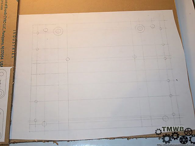
So today I went and bought some drafting supplies. A t square, circle guide, and some triangles for checking square. I also picked up 2 cool large circle drawing aids which will be used on future projects.
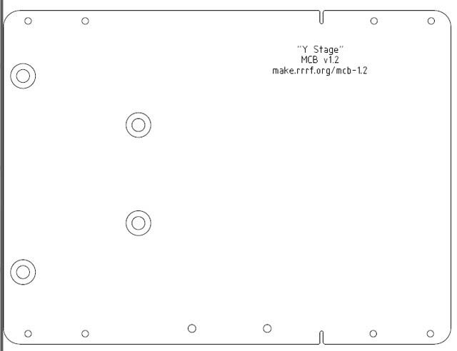
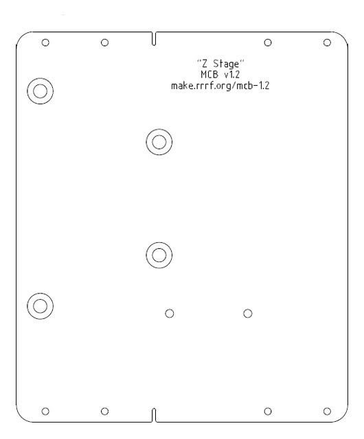
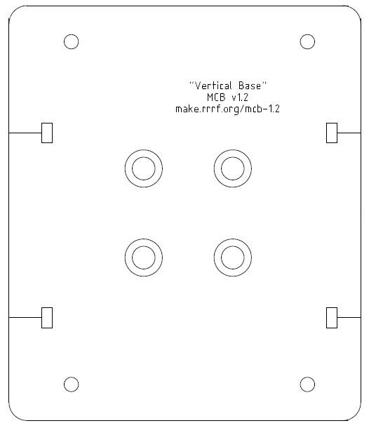
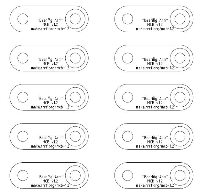
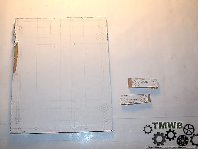
While typing this I realized that I have not posted the original drawings that your supposed to print out. I have saved them as .jpg and re sized them for better viewing here. If you are following this build log with the intent of building your own McWire please note that these are not the right size.
X stage- The large circles with a circle in the middle is the ones that must be countersunk so the 5/16" machine screws sit flush with the surface of the plexi.
Y stage
Z stage
Vertical base. This is what mounts to the 4" flange. The rails and z stage mount to this.
Bearing arms for the non fixed position bearings. X and Y stage only. Only 4 are needed.
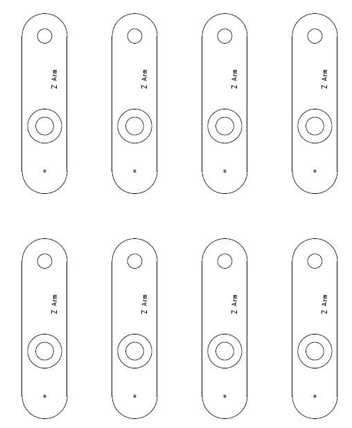
Bearing arms for the Z stage. Only 4 are needed.
-
Re: My RepRap Build. (3d printer for those not in the know)
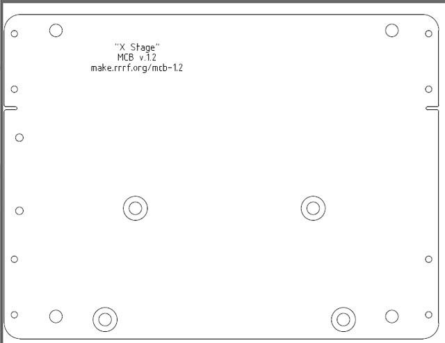
Just finished the technical drawing for the X - Stage. Here is a scaled down image so you guys can see what I am doing.
-
Re: My RepRap Build. (3d printer for those not in the know)
Those are some pretty complex drawings you got going on :rolleyes:, wish I could do something of that level.
Looking good as always and with everything you do. Keep up the good work mate!
-
Re: My RepRap Build. (3d printer for those not in the know)
Ever had one of those nights where you could not sleep because you wanted to work on something. Tonight was one of those nights. I went ahead and cut out the new x stage and assembled it. It fits perfectly and moves smooth as butter. I will post pics tomorrow.
-
Re: My RepRap Build. (3d printer for those not in the know)
Mmmmm technical drawings.... Good job so far, keep it up! :)
-CollinstheClown
-
Re: My RepRap Build. (3d printer for those not in the know)
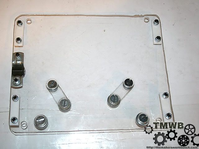
Update time:
So I got a little restless last night and could not sleep. So what better to do than work on the McWire. I cut the new X stage plexi out and assembled all if the parts.
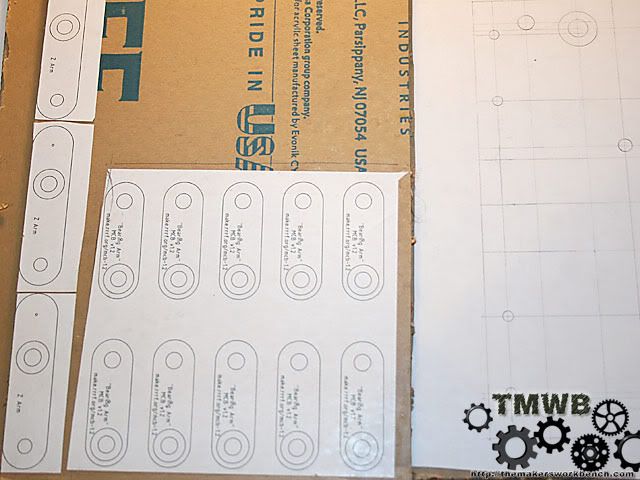
The first thing I had to do was glue the hand drawn X stage to the plexi. An Elmers glue stick make quick work of this. I used a ruler to smooth out any bumps and ripples.
Did the same with the bearing arms
Then I had to cut them out.
My jigsaw is a little old and the cuts were a little rough. Nothing a little sanding on the drum sander wouldn't fix. I pre-drilled all the holes.
Then counter sunk the 4 holes that required it.
Removed the protective paper and everything looks great.
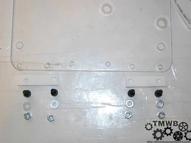
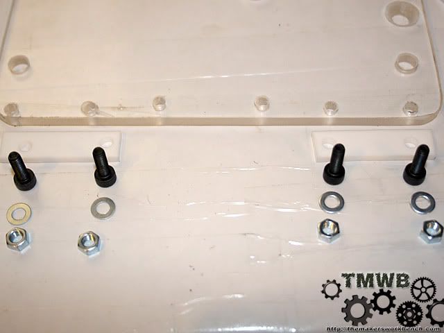
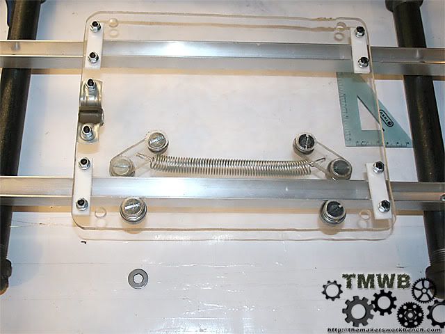
Now I laid out all of the hardware and parts I needed to assemble the X stage.
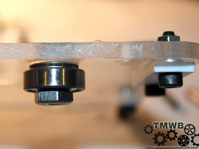
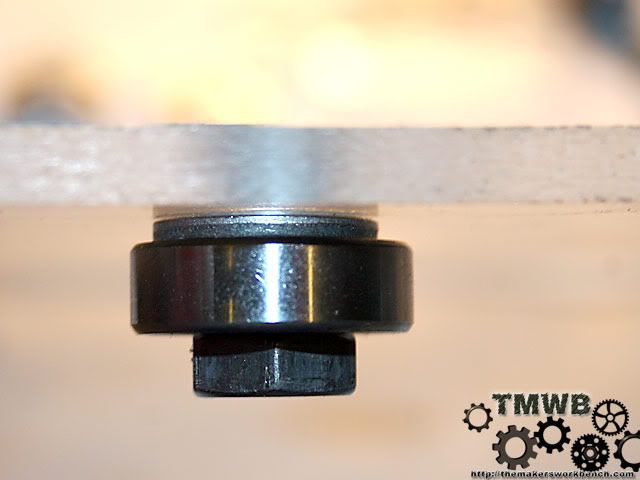
Next I attached the PTFE slide bearings and the Skate bearings that go on the outside of the front rail.
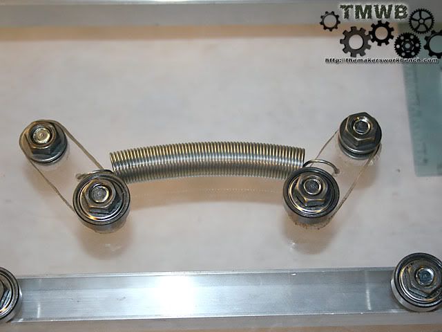
The next step is to attach the remaining 2 bearings to the bearing arms. The order goes like this. 5/16 flat head screw>bearing arm> 5/16" flat washer>skate bearing>hex nut.
Now lets build the captive nut. This is the nut that will convert the radial motion of the lead screw and convert it into linear motion. You need a 1/4 - 20 coupling nut and a roll of electrical tape. Wrap the nut with the tape until it is thick enough that it just fits inside of the conduit support. You want it to be just snug. Not so bulky that it has to be forced to fit.
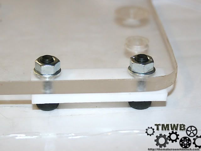
Now lets finish assembling the x stage. Install the bearing arms onto the bottom of the plexi using 5/16 machine screws. Place a 5/16 washer between the bearing arm and x stage plexi. Then slide on the bearing arm. Add another washer then a hex nut. Repeat for the next side. Then bolt on the captive nut using the same M5 cap screws that you used for the PTFE bearings.
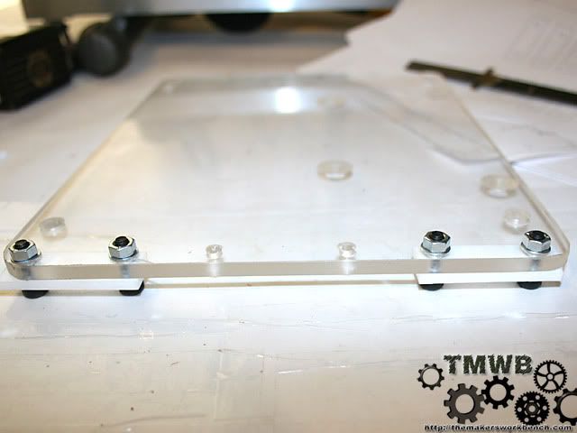
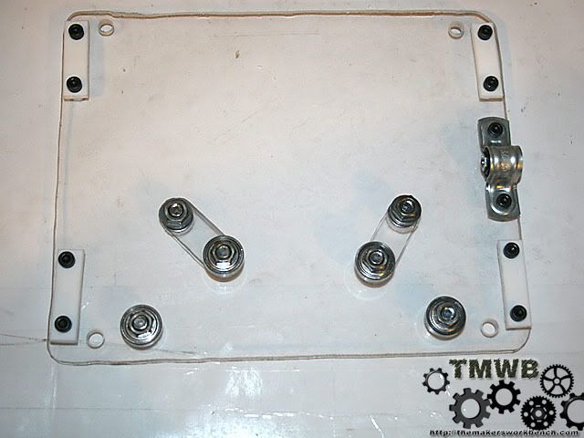
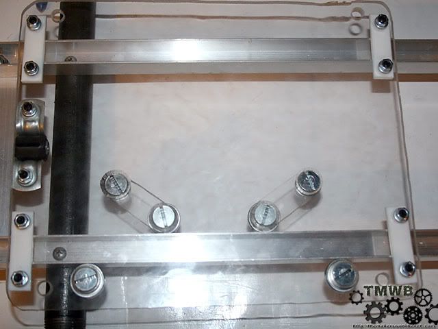
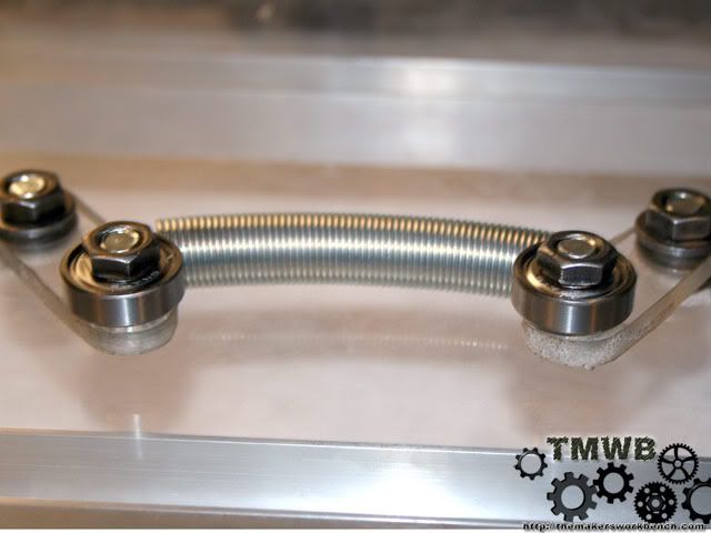
Now put it on the rails and make sure everything fits.
Now we need to add some tension to hold the bearings on the bearing arms firm against the rail. A 4" 5lb extension spring will work nicely. I drilled a 3/16" hole in the middle of the bearing arms and bent the spring ends so I could slide them though the holes. Then I bent them back flat with the bearing arms. The excess spring loop is tucked inside the spring.
Now I am off to build the Y stage.
-
Re: My RepRap Build. (3d printer for those not in the know)
This reminds me alot of the easy mill, but a bit more pro. Not to mention its a printer.
-CollinstheClown
-
Re: My RepRap Build. (3d printer for those not in the know)
The main design is a previous design for a Desktop CNC router by Tom McWire. He posted the design under the GPL and the RepRap core team modified and improved upon the design to make it more precise and stable. The only real major difference is the print head will be bolted to the z stage instead of a dremel. I have been thinking of putting together a parts kit that will include everything but the stepper motors and the electronics.
-
Re: My RepRap Build. (3d printer for those not in the know)
nice work! lookin good. +rep for the work on the drawings!
-
Re: My RepRap Build. (3d printer for those not in the know)
Thanks for the rep. On a side note does anyone know of a good source for solder paste in a syringe.
-
Re: My RepRap Build. (3d printer for those not in the know)
Looking good... Any idea what your maximum travel distances are for this? all directions?