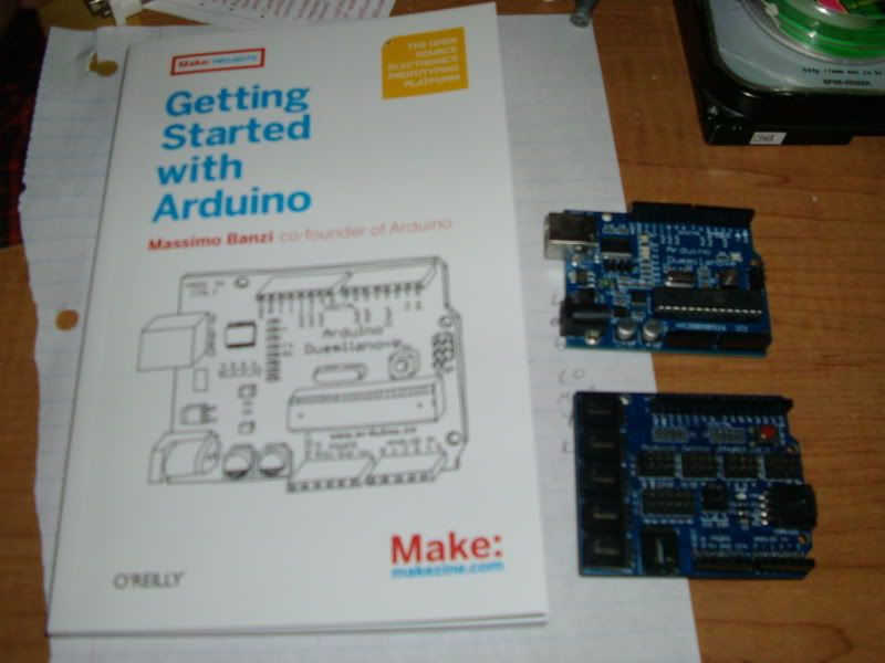
Yea buddy! an ATMega328 Arduino, Arduino sensor shield and "Getting Started With Arduino" book!
gonna have some fun with this puppy! :banana:

Printable View
Yea buddy! an ATMega328 Arduino, Arduino sensor shield and "Getting Started With Arduino" book!
gonna have some fun with this puppy! :banana:
ok I've gone through the book (well as far as I can go with the components I have) and I've learned a lot. Made an LED blink, played with PWM, make an LED turn on/off with a momentary switch
I'd say it was a good first step toward my goal of having a servo controlled based on a temp sensor :up:
Excellent! Glad to see you got the Arduino.
Keep us posted on your work.
Sweet, Another member joins the dark side!
lol yep. I just ordered a few things from adafruit for the project I want to do. till then I'll keep messin with this thing!
I have a pretty cool Random color RGB LED fader code you should have fun messing around with. Just change the delays for faster or slower fade time. It works with common anode RGB leds.
It uses pins 9, 10 and 11 and remember to use resistors on each anode. Cathode to Ground.
Code:float RGB1[3];
float RGB2[3];
float INC[3];
int red, green, blue;
int RedPin = 10;
int GreenPin = 11;
int BluePin = 9;
void setup()
{
Serial.begin(9600);
randomSeed(analogRead(0));
for (int x=0; x<3; x++) {
RGB1[x] = random(256);
RGB2[x] = random(256); }
}
void loop()
{
randomSeed(analogRead(0));
for (int x=0; x<3; x++) {
INC[x] = (RGB1[x] - RGB2[x]) / 256; }
for (int x=0; x<256; x++) {
red = int(RGB1[0]);
green = int(RGB1[1]);
blue = int(RGB1[2]);
analogWrite (RedPin, red);
analogWrite (GreenPin, green);
analogWrite (BluePin, blue);
delay(25);
for (int x=0; x<3; x++) {
RGB1[x] -= INC[x];}
}
for (int x=0; x<3; x++) {
RGB2[x] = random(956)-700;
RGB2[x] = constrain(RGB2[x], 0, 255);
delay(10);
}
}
thanks I"ll play around with that!
now does the arduino always put out 5v? or if I hook a 12v power supply will it output 12v on a different pin?
Arduino will only output 5v unless you have a model like my seeeduino that also does 3.3v.
ahhh ok. so how would I go about powering a 12v fan then? :?
I think (not even 50% sure) that you can power the fan with 12v and use a PWM pin on the duino to control the PWM line on the fan.
ok I found this code
http://www.arduino.cc/playground/Com...ib/Thermistor2
and wired up a spare temp sensor from my sentry 2 fan controller per their schematic
and changed it to 4800 baud (code shown is changed) so it wasn't updating quite so quickly. now to work on getting these readings to control the servoCode:#include <math.h>
//Schematic:
// [Ground] ---- [10k-Resister] -------|------- [Thermistor] ---- [+5v]
// |
// Analog Pin 0
double Thermistor(int RawADC) {
// Inputs ADC Value from Thermistor and outputs Temperature in Celsius
// requires: include <math.h>
// Utilizes the Steinhart-Hart Thermistor Equation:
// Temperature in Kelvin = 1 / {A + B[ln(R)] + C[ln(R)]^3}
// where A = 0.001129148, B = 0.000234125 and C = 8.76741E-08
long Resistance; double Temp; // Dual-Purpose variable to save space.
Resistance=((10240000/RawADC) - 10000); // Assuming a 10k Thermistor. Calculation is actually: Resistance = (1024/ADC)
Temp = log(Resistance); // Saving the Log(resistance) so not to calculate it 4 times later. // "Temp" means "Temporary" on this line.
Temp = 1 / (0.001129148 + (0.000234125 * Temp) + (0.0000000876741 * Temp * Temp * Temp)); // Now it means both "Temporary" and "Temperature"
Temp = Temp - 273.15; // Convert Kelvin to Celsius // Now it only means "Temperature"
// BEGIN- Remove these lines for the function not to display anything
Serial.print("ADC: "); Serial.print(RawADC); Serial.print("/1024"); // Print out RAW ADC Number
Serial.print(", Volts: "); printDouble(((RawADC*4.860)/1024.0),3); // 4.860 volts is what my USB Port outputs.
Serial.print(", Resistance: "); Serial.print(Resistance); Serial.print("ohms");
// END- Remove these lines for the function not to display anything
// Uncomment this line for the function to return Fahrenheit instead.
//Temp = (Temp * 9.0)/ 5.0 + 32.0; // Convert to Fahrenheit
return Temp; // Return the Temperature
}
void printDouble(double val, byte precision) {
// prints val with number of decimal places determine by precision
// precision is a number from 0 to 6 indicating the desired decimal places
// example: printDouble(3.1415, 2); // prints 3.14 (two decimal places)
Serial.print (int(val)); //prints the int part
if( precision > 0) {
Serial.print("."); // print the decimal point
unsigned long frac, mult = 1;
byte padding = precision -1;
while(precision--) mult *=10;
if(val >= 0) frac = (val - int(val)) * mult; else frac = (int(val) - val) * mult;
unsigned long frac1 = frac;
while(frac1 /= 10) padding--;
while(padding--) Serial.print("0");
Serial.print(frac,DEC) ;
}
}
void setup() {
Serial.begin(4800);
}
#define ThermistorPIN 0 // Analog Pin 0
double temp;
void loop() {
temp=Thermistor(analogRead(ThermistorPIN)); // read ADC and convert it to Celsius
Serial.print(", Celsius: "); printDouble(temp,3); // display Celsius
temp = (temp * 9.0)/ 5.0 + 32.0; // converts to Fahrenheit
Serial.print(", Fahrenheit: "); printDouble(temp,3); // display Fahrenheit
Serial.println(""); // End of Line
delay(100); // Delay a bit... for fun, and to not Serial.print faster than the serial connection can output
}
one step closer!
found this:
with this:
which controls the servo and is much simplerCode:// Sweep
// by BARRAGAN
#include
Servo myservo; // create servo object to control a servo
// a maximum of eight servo objects can be created
int pos = 0; // variable to store the servo position
void setup()
{
myservo.attach(9); // attaches the servo on pin 9 to the servo object
}
void loop()
{
for(pos = 0; pos < 180; pos += 1) // goes from 0 degrees to 180 degrees
{ // in steps of 1 degree
myservo.write(pos); // tell servo to go to position in variable 'pos'
delay(15); // waits 15ms for the servo to reach the position
}
for(pos = 180; pos>=1; pos-=1) // goes from 180 degrees to 0 degrees
{
myservo.write(pos); // tell servo to go to position in variable pos
delay(15); // waits 15ms for the servo to reach the position
}
}
now...the Arduino will have its own power supply. I need to have a signal wire (5v from PSU, or even 3V for PWR LED from MB) tell it to start and stop. I want it to have the servo all the way to one position to start, then once it gets its signal, to run the code loop. then once it loses its signal, to go back to the set position
I'm going to play around with the coding and see what I can get it to do
also, anyone see anywhere in that code that will make the servo move more? it moves, but not much. less than 1/4 turn from 75ºF to around 140ºF
alright CJ, tell me what you think. the only thing I'll need to tweak is the map(val) section, but i'll have to wait until the system is assembled. this will set the range of the temp sensor it reads, as well as how far the servo moves based on said temp range.
it reads input voltage on pin 7 (5v from power supply). if no voltage is present (computer off), it sets the servo to a set position (vents closed), If it detects 5v on pin 7 (computer on), it proceeds with the loop. The only thing I can't seem to fix is the time between when voltage is taken away from pin 7 and the time it sets the servo. seems to take a few seconds for it to set. any suggestions on how to fix this?
also, it seems to jitter occasionally when reading the temps. if I leave the sensor out in the air, the servo will jitter. if I stick it on the heatsink on one of my 3870x2's (140ºF) it's still. I tried changing the delay to a higher value, but that makes the servo jumpy instead of having a smooth transition. any thoughts?Code:// Controlling a servo position using a temperature sensor
// by Michal Rinott <http://people.interaction-ivrea.it/m.rinott>
// edited 5-12-2010 by Will Lyon to include base setting for servo if voltage not detected on pin 7
#include <Servo.h>
#define CONTROL 7
Servo myservo; // create servo object to control a servo
int temps = 0; // analog pin used to connect the temp sensor
int val; // variable to read the value from the analog pin
void setup()
{
pinMode (CONTROL, INPUT); // sets the control pin to input
myservo.attach(9); // attaches the servo on pin 9 to the servo object
}
void loop()
{
val = digitalRead(CONTROL);//read input of pin 7 and store it
if (val == HIGH){ // reads whether or not 5v is present on pin 7, if 5v present, continue:
val = analogRead(temps); // reads the value of the temp sensor (value between 0 and 1023)
val = map(val, 400, 900, 0, 179); // scale it to use it with the servo (value between 0 and 180)
myservo.write(val); // sets the servo position according to the scaled value
delay(15); // waits for the servo to get there
} else {
if (val == LOW); // if no voltage present on pin 7, continue
myservo.write(10); //sets servo position to 10 if no voltage is detected on pin 7
}
}
There is only one delay in the code and its at 15ms so I think the long time is the physical delay in the duino detecting no voltage.
A cool idea I just thought up would be for you to add some accent leds to the vents and as they open they could fade from one color to another. Like when its cool they would light up blue and as the vents open they would slowly fade to red.
well I'm going to put 5mm RGB LEDs in the two top 140mm fans, and those will be connected to the RGB controller from John @ PCBoard.ca, which will also be connected to the rest of the accent lighting in/on the case :D