-
Project Open Air Mk 2
Welcome back, TBCS!!! :banana:
I've been asked to come along with decryptedtech.com to CES 2014 to help cover the show (yay!), and thought it would be cool to put together an open-air case that's a true showpiece for the hardware it uses. Hopefully we'll see it at the show in Las Vegas with some awesome new gear mounted to it.
This project will be an evolution of my last piece, Open Air, with a few improvements to draw the eye and really showcase what's in it (or on it in this case). That was the idea then, as we all know that modern enthusiast-grade hardware is made to be seen.
I'll start with a huge thanks to my sponsors!
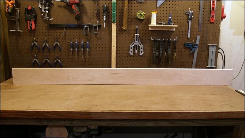
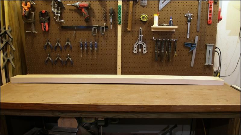
On to the build! I'm blessed with an excellent local hardwood dealer, and started with a long thick block of rock maple:
I was amazed at how much that chunk of wood was bowed, given its thickness. My bench isn't perfectly flat but it's better than THAT. I'd say it was cut before it was properly dried but I can work with it. I'll be cutting small pieces out of that chunk, I can get them flat square and true.
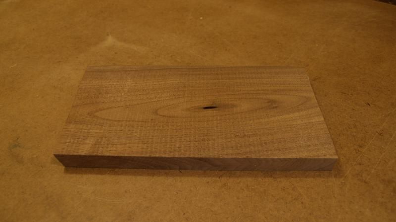
One small piece of leftover walnut:
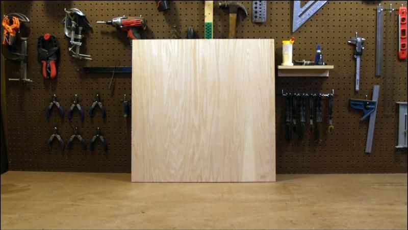
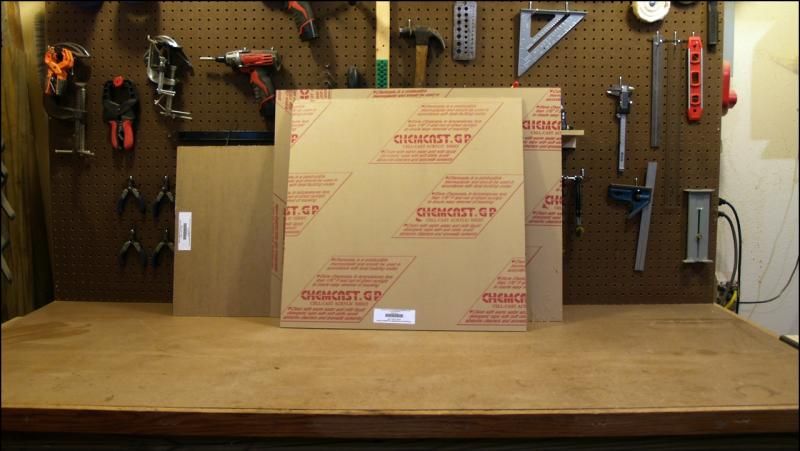
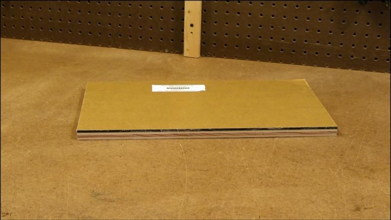
Add to the stockpile a 2x2 piece of 1/2" birch plywood to fill in the base. I hadn't planned to use plywood at all but this piece will be completely invisible once the project is done.
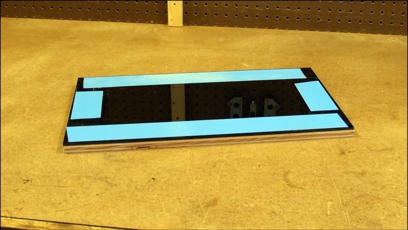
And the requisite acrylic sheet. I used gray translucent acrylic for the last project because I had some left over from another piece, but since I ended up painting it black anyway I just went with solid opaque black on this one. I'm really interested to see how the edges look after machining and polishing.
Those are the pieces that will make up the entire case. System parts are being put together now.
Check back for updates, thanks for watching
-
Re: Project Open Air Mk 2
The base of this project is going to be the most complicated part I think, but I've tried to keep even that fairly simple.
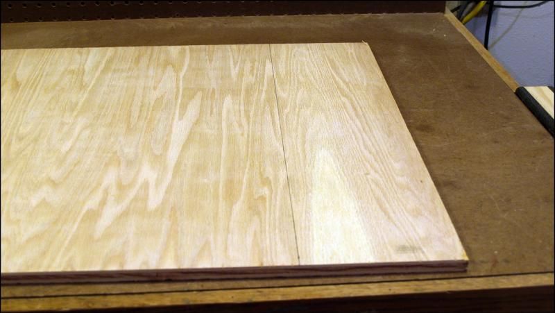
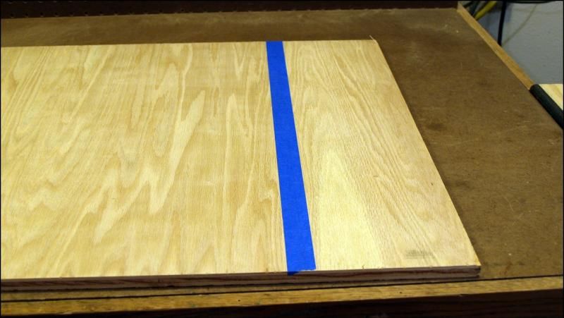
To start, I had to cut that chunk of plywood to make the core of the base. One thing I learned from you modders who work with metal (hat's off to you guys, don't know how you do it) is using masking tape for cuts.
Even the best plywood can splinter and ruin an edge, this really helps!
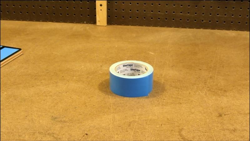
This piece was cut 1/4" overlength on both sides, then I got the chance to use one of the most useful tools ever devised: double-sided tape.
That's some really good stuff there, once the acrylic is in place it won't come off without tearing off pieces of the plywood. This piece was also cut oversize and taped in place, then the whole assembly was cut to final size to ensure the edges were perfectly aligned. It has to fit into a hole exactly the same size later.
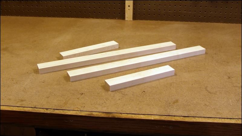
There was a lot of work done cutting, jointing and planing that bug chunk of maple down to the small pieces I need for the base frame, and pics were taken but somehow lost. These are the finished pieces:
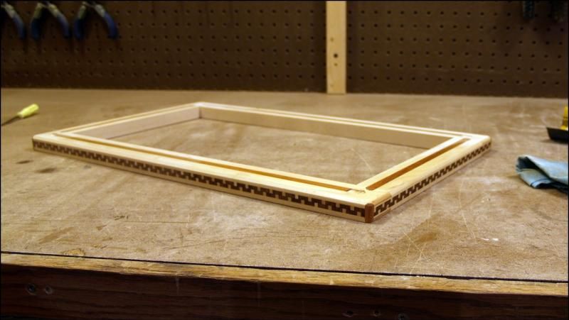
Once those were assembled into a simple rectangle big enough for an ATX motherboard and at least one accessory (the top layers will follow this same size pattern), the intricate work started.
At this point the base is all but finished, just have to drill and counterbore screw holes for the uprights. I'm happy to say it is turning out very well thus far.
Uprights are next, hopefully the next update will see them in place and I can start cutting the acrylic.
-
Re: Project Open Air Mk 2
Good start already, I loved your last one. Can't wait to see this one!
-
Re: Project Open Air Mk 2
Thanks! As mentioned, this will be very similar to the last piece but I wanted it bigger, plus there will be an additional top shelf that's tilted outward toward the front of the case to really say "LOOK AT ME!". The middle and upper shelves will be topped with black acrylic also. Those changes, along with the inlay work should really make it the showcase I'm wanting it to be.
-
Re: Project Open Air Mk 2
Dang. I love that woodwork. Looking forward to this one.
-
Update: Columns!
Got the uprights mostly finished today. First off, apologies for the graininess of the images, had some trouble with the postprocessing.
The easiest part was drilling and counterboring the holes in the base for the mounting screws:
Nice and clean, I love this wood!
The columns are made from simple square maple blocks 1 1/4" on a side and 7 inches long:
I ran them across the table saw a couple of times to give the corners a more interesting profile:
The plan is for the two acrylic panels on the front and rear of the case to be fixed, and the two side panels to be removable for access. To keep a clean visible edge and improve stability in the whole unit I needed to cut slots in the inner face of all four columns. I happened to have the perfect tool for the job, a 12mm carbide square-nosed end mill. In my router table it cut the perfect slot for the 3/16" acrylic.
Unfortunately, I had a mishap. The end mill wasn't chucked securely in the router and slipped during the pass on the third column. This is the result:
I had hoped it was small enough not to be visible when the acrylic was in place, but no suck luck.
%$$#^&*^*!!!
Yeah, that's not going to work. Honestly I'm really lucky it didn't come out of that router at 25,000 rpm. Luckily I've got plenty of maple so I was able to make another column and finish the slots.
The side panels posed another problem. On the last version of this case, I glued stop blocks to the inside of the columns like this:
Then I glued tiny magnets to the stop block and the back of the acrylic panel. They snapped in place fine but you have to use a suction cup to get them off. Also, if there is *ANY* variation from 90 degrees in the columns you have to cut the sides of the acrylic to exactly the same angle to avoid visible gaps. I went through four pieces of acrylic on the last one getting one angle right.
This time I decided to put the acrylic on the *inside* of the columns. That way it can be slightly wider than the column gap and any angle deviation will be invisible. To do that I cut a notch out each column:
The panels will have to be put in at an angle and then pulled up against the inside of the notch. Since I don't have a slot to hold it I needed a retention mechanism. Magnets FTW!!
I drilled three holes in the back side of each notch and pressed magnets into each hole.
When I make the panels I'll cut a groove into the ends of each one and use epoxy to secure a thin strip of metal to the panel. When the panel is inserted into the case and slid back toward the outside the magnets will grab the metal and hold it in place. (That's the theory anyway, we'll see.)
I am also glad to say that the inlay work on the columns came out as well as I had hoped. Naturally there is some sanding to be done yet, and the finish will change the overall appearance but here's a good idea of what it will look like:
That's all for today, next up I have to figure out how to get the columns screwed to the base while still keeping them at 90 degrees. After that it's on to making acrylic shavings!
Thanks for tuning in!
-
Re: Project Open Air Mk 2
Wow! The inlays look great. Can't wait to see the end result.
-
Re: Project Open Air Mk 2
This is what I have been waiting for, I absolutely love the wood inlaid USB you made for me and have been wanting to see a wood inlaid case.
-
Update: Panels
Long-delayed update time. I had to stop work on the bottom portion of the case while I'm waiting for a new PSU to come in. I need it on hand to continue there as I'll be modding it for for mounting purposes and the mount for the DVD drive is dependent on it as well. Onward and upward as they say.
I'm going to need two panels to sit on top of the columns I made, one horizontal to top it off and one tilted at 30 degrees to show off the working hardware. I want these two panels to be identical, and they need to be not only attractive but strong. One of the reasons for the delay in this update was trial and error. I considered making a thick frame from maple with a core of plywood like I did for the base, but the top of each panel will be opaque black acrylic, so the edges wouldn't look right. I tried a couple of different options before coming up with the answer.
First I went and bought a 2 x 4 piece of 1/4" MDF and cut two panels 1/4" under my desired final dimensions:
I discovered the hard way a long time ago that 1/4" MDF is like 1/4" acrylic or 1/4" plywood or pretty much anything you can buy with a thickness measured in a fraction of an inch: it's not. It's thinner, every time. In this case that didn't matter, thankfully. I took some of the extra maple I had and cut eight strips exactly as thick as the MDF and 1/2" wide. (Slightly less actually, just to keep up with the trend...)
After some more trial and error on how best to clamp these edges to the MDF panels I came up with this setup:
Not easy but in the end I would up with two panels of MDF with solid maple edging slightly larger than what I wanted in the end:
Since I knew the top of each panel was going to be 3/16" acrylic, and I was going for uniformity, I decided to laminate two sheets of acrylic on top and bottom of my MDF panels. Anyone who's worked with cast acrylic knows that while it really is a joy to work with given some practice, it can be a problem to glue to anything other than other acrylic. I went through several different kinds of adhesive before I settled on Loctite Super Glue Ultra Control Gel. Kind of pricey at almost a dollar a gram but nothing holds like this stuff. The best superglue in the world hands down. Here is one of the panels, with one of the acrylic pieces cut and stripped of one side of its protective layer. Looks like a black mirror, just exactly what I'm wanting.
I thought that last clamp setup was intricate until I went to glue these together. I had to work fast, and I wanted every inch of the acrylic to make contact with the MDF sheet. Good thing I have a lot of clamps!
My biggest concern at this point was gaps at the edge. The edges will be polished to a mirror shine and will be extremely visible so gaps are very very bad. Thankfully it came out perfectly!
After I had all four acrylic panels glued in place I cut the two panels to size. Flawlessly even surface with zero gaps:
Given the profile that I gave the base and the columns I can't leave these square so I made a bevel around all four edges of both sides of both panels. They're rough now from the saw but they'll polish up like glass.
Now for a word from our sponsors! The folks at Kingston were kind enough to donate some awesome pieces of hardware for this build: a 16GB kit of HyperX Beast DDR3 1866 memory and a 240GB HyperX SSD. Thanks guys!
It was the inclusion of the SSD that determined the footprint for this entire build (and thus the size of these two panels), since I need enough room on the upper panel to display the "shiny stuff". I decided on 12" x 20", here's that shiny new SSD alongside an old dead ATX motherboard I keep around for just this sort of thing:
I got it right! Like anyone else who's worked with acrylic I *really* want to peel that paper off of there and see what it will look like all shiny and black but there are two good reasons not to: I still have marking drilling and tapping to do on them and I'm working in a woodshop. Shiny black acrylic and sawdust do not a pretty picture make.
That's it for now, next update I hope to have the securement portion of the columns done and the side panels installed. Thanks for watching!!
-
Re: Project Open Air Mk 2
This is going to be good and I am glad motherboards look much better now
-
Re: Project Open Air Mk 2
Quote:
Originally Posted by
Stonerboy779

This is going to be good and I am glad motherboards look much better now
Me too. It was the improvements in the aesthetics of hardware that made me decide to make the last one (and this one) the way I did. I was designing a case and realized there was no reason to hide this awesome-looking stuff inside a box.
It was the modders and enthusiasts like us that made the industry pay attention and make our hardware look as good as it does. Way to go guys! :D
-
Update: Transport resistance
Another small update tonight. After looking over the design for this case I've decided that some changes are in order. As I've said before this is primarily a showcase for hardware. I've been taking into consideration the trip to CES in January, but it's possible that my sponsors may want to use the case at other venues after that, which means not only shipping it but having it unpacked, assembled, repacked and shipped back by someone other than me. I have to take that into consideration in the design. Transport is rough.
To that end I've decided to change a couple of things, starting with the columns. These are structural weak points. If I were making it to sit on my desk and not move they're actually overkill but if it's going on the UPS truck or by FedEx, and then hoisted around by someone who doesn't know how it's put together they're not nearly enough. I decided stronger mounting was the place to start, and turned to these:
These are steel inserts, 1/4-20 internal thread. The external threads are very aggressive and once seated in the maple will never move. Couple that with hex-drive button-head bolts and we've got a winner. The problem came in installation. The hole for the insert had to be perfectly in line with the center of the column. If it was crooked at all that angle would translate to the bolts and create gaps or if tightened down too tight it could crack the inlay or even the acrylic on the upper portion.
I own a fairly nice smaller drill press, which would be the perfect tool for the job, but (there always seems to be a "but") it's too small. The columns are longer than the distance from the table to the drill chuck even at its lowest setting. Obviously I couldn't use the table, so I had to make a jig, something that would hold the column perfectly perpendicular to the base of the machine, since I know that's perpendicular to the drill spindle. Took a while, and as usual with jigs ended up being deceptively simple:
Simple but effective. I took each column off of the base and marked the drill points on the top since I was putting inserts on both ends. I used the existing holes from the smaller mounting screws for the bottom since they were already lined up with the holes in the base.
Clamp it up, center the column in the jig on the drill point and clamp the jig down...
And dive in!
I'm happy to say that went perfectly, ended up with eight nice clean straight holes right where I wanted them. I knew from experimenting earlier that I also needed help installing the inserts straight though. Even with a clean hole the external threads are pitched steeply enough that it will actually drive itself in crooked. I already had the answer thankfully.
I used a piece of 1/4-20 all thread with a lock nut on it as an installation tool.
I chucked that into the drill press, re-clamped the columns and used the press to apply straight downward pressure while I sunk the inserts with a wrench:
Worked perfectly!
So now all four columns have the course-thread steel inserts in them and are mounted back to the base. Once the center section is also mounted with them you'll be able to pick it up there with no worries. One problem down.
That solves the problem of straight up and down force, but I still have to adapt to compensate for racking motion. Even with them bolted down, pressing sideways on the top of one of those columns will be applying force to those bolts and the base with a seven-inch lever. I have to immobilize them side-to-side as well as up and down.
That's the plan for the next update, stay tuned and thanks for watching!
-
Re: Project Open Air Mk 2
-
Re: Project Open Air Mk 2
That's a genius way of sinking in the inserts and I think I'll try and remember that for future reference.
-
Re: Project Open Air Mk 2
Quote:
Originally Posted by
Stonerboy779
That's a genius way of sinking in the inserts and I think I'll try and remember that for future reference.
I can't take credit for that one, I actually got the idea from one of our master modders, Mach. He uses this technique when tapping holes, I just adapted it. Thanks, Mach!
-
Re: Project Open Air Mk 2
I really like how this project is taking shape. Very few people work in hard wood anymore.
-
Re: Project Open Air Mk 2
Indeed it's coming along nicely! I'll see you at CES! I'll also be filing that insert threading idea away for future use :D
-
Re: Project Open Air Mk 2
Quote:
Originally Posted by
SXRguyinMA
Indeed it's coming along nicely! I'll see you at CES! I'll also be filing that insert threading idea away for future use :D
Awesome, we'll have to coordinate and get together sometime!
-
Update!!
Finally got some free time to work on this thing again! Made a hell of a mess and screwed up one brand new power supply but progress was made.
First step was a hole in the top. Though the only things inside will be the PSU and optical drive, the PSU will need to breathe and I need a way to get the cables out of the box and onto the motherboard. I kept it as small as I could to minimize visibility in the finished product. After rough assembly it turns out this hole could be a LOT bigger, so I may end up enlarging it if the cables are a problem.
After bolting that back to the columns with the inserts I finished last update I had to make a riser for the display shelf. This will be tilted outward to show off the motherboard and the SSD so I had to figure the optimal angle. I settled on 30 degrees and started cutting scrap.
Each riser ended up being made of four pieces: three pieces of scrap hardwood for the structure and one piece of acrylic for the outside to hide it.
Each of these is held in place with five screws from underneath and will also be glued in it final form. No reason the risers ever have to the come off of the middle shelf, and since I'm sure the case will get picked up by the display shelf that area has to hold the weight of the lower portion in motion.
I finally got to tear into one of the coolest parts of this project tonight: Cooler Master was kind enough to donate one of their Esiberg 240L Prestige watercooling kits, thanks guys!!
I've used a couple of these all-in-one products, from Corsair and Antec but this piece from Cooler Master is easily the slickest setup I've seen. It comes with the usual integrated pump/block/reservoir, 240 radiator and 2 fans, but the Eisberg is made with actual compression fittings and a fairly standard tubing size, so the user can add blocks, radiators, reservoirs, tubing etc to their system as they need to. The block/pump/reservoir even has a dedicated fill port.
This flexibility saved me a lot of trouble as the tubing was never meant for this application and was far too short. As soon as I took it out of the box I took it apart and drained it. I'll warn anyone reading this that might decide to try it, the paint scratches easily. It's flat black so it will be easy to touch up, but be advised. The "collar" portion of the compression fitting has two holes in it opposite one another so I'm sure there is a spanner of some sort available to avoid this issue.
Here is the radiator out of the Esiberg system with my decidedly low-tech mounting setup:
I pondered on mounting this for a long time and finally realized that while this case is a showpiece, it is not a showpiece that anyone will ever open or look inside of. That opened any number of construction and mounting options.
Obviously the radiator on this will be at the rear of the case, hidden away under the overhang of the display shelf. That puts it right on the beveled edge of the risers. Anyone see a problem with this next picture?
Out came the Dremel and hacked off that little corner that was in the way. At that point I thought I had it. Went to put the display shelf in place to take some measurements, turns out the front edge of the fans was a fraction of an inch too high. Since I couldn't move the whole setup backward or the radiator would overhang the rear of the machine, I had to put the fans on the table saw.
Finally got that settled, got the radiator mounted and got a piece of acrylic cut to hide the scrap-wood construction:
After much cursing and pacing I finally got the holes drilled properly in the display shelf and the inserts mounted in the risers, so it is finally bolted down.
This thing is FINALLY starting to take shape!
That's all for today. Next time, how to construct a PSU mount that can withstand shipping without destroying the PSU in the process. I hope.
-
Re: Project Open Air Mk 2
This is going to be so good. I would also love to see wood inlay GPU back plates haha
-
Re: Project Open Air Mk 2
This case is truly a work of art! Your hard work definitely shows.
-
Finally some progress!!
I'm running out of time to get this thing done, but making progress!
First off, PSU mounting. For this build I'll be using a new EVGA 500B power supply. Not a tremendous amount of power but this is really a lower-power system and the 500B is very quiet and fairly small.
Pretty thing isn't it? Everything EVGA makes is pretty if you ask me. So anyway, this is where it has to sit:
I can't mount it in the usual way, with the four mounting screws in the rear. The back wall of the case is just acrylic and I have to make this thing UPS-resistant. (Nothing is UPS-proof.)
I decided to mount it from the side and bolt the mounts to the floor of the case with some angle iron I had left over from another project:
In the end it will sit like this:
In order to make mounts I had to get it open. There have GOT to be screws holding it together but I'll be damned if I can see any.
I learned the hard way a couple of years back that these labels that the manufacturers use are usually very thick and hide screws very well. If you run your thumbs along the sides pressing hard you'll uncover them with a dent in the sticker over the screwhead:
A little time with an Xacto and there that little sucker is!
Take out four screws and the top lifts right off.
If you do this, be careful. It's easy to forget that the fan is still connected and yank something loose. There is usually some hardened resin material on the connector itself to hold it together, you may have to cut that loose with your Xacto also.
Once that was unplugged I pulled the fan off to get the fan grill out of it. That grill isn't needed inside and is way too cool to hide.
Ok, so I got the PSU wide open and I'm planning the mounts. Since I'll be mounting it from the sides, I had to be careful the mounting hardware isn't going to touch anything it shouldn't when I'm done.
Locations chosen, I turned the outer casing on its side on the bench and drilled four 1/4" mounting holes:
I chose button-head bolts for their low clearance.
Installed:
Once the bolts were very firmly in place I put the whole thing back together again (remembering to plug in the fan, I've been down that road before too):
Unfortunately, when I placed the angle iron beside the new bolts to check the fit, the bolts were too high!
Honestly, this probably would have worked fine but I wanted them in the middle of the angle. No problem, small piece of scrap acrylic under each one raised them just right.
After that is was just a matter of drilling matching holes in the angle iron, sliding it over the bolts and locking it on with nuts.
I drilled four holes through the floor of the case and four matching holes in the lower part of the angle. Four Nylok nuts later and this PSU isn't going anywhere.
I also managed to get the rear acrylic panel cut. The fit was tight enough that I had to cut off the edge of the stickers on the PSU to slide it in place.
------
Ok, the PSU is in place and as solid as it is humanly possible to make it. Now for the DVD drive.
For this I used two pieces of oak, 1 inch square and 18 inches long. Drilled through holes and mounted them to the bottom mounting holes on the DVD drive with long M3 bolts.
Now I needed something to mount those to. Earlier I realized I was going to have a problem with racking, side-to-side or front-to-rear motion, since the weak points in this design are the tops and bottoms of the columns. To eliminate the front-to-back racking I had to eliminate the fancy magnetic-retention setup I had for the side panels and glue them in. After that I cut two pieces of 3/4" oak and glued them to the inside of these panels and then screwed them in from underneath. One racking problem solved, plus it gives me a perfect anchor point for the DVD drive stringers.
Done. I can literally pick up this entire case and turn it 90 degrees in the air touching nothing but the DVD drive. That should do. :)
----
After a lot of measuring, drilling and some time machining on the router table the front panel is done also!
As it's a very high-visibility piece I'll leave the paper on it for the time being.
---
Only one more thing for the front: the power switch. I bought a gloss black Bulgin switch and I love it, but I figured out it would get lost in that big gloss black front panel so I wanted a way to make it stand out.
Thin strip of maple:
On the drill press to cut out the switch hole:
Swapped the Forstner bit for a hole saw, without moving the drill press table or the wood, so that hole stayed centered on the spindle:
That got me a rough maple circle:
With a little time on the router table and some sandpaper it makes a nice switch ring:
In a piece of scrap just to see what it will look like:
That's it for today but that was a lot. The entire bottom portion of the case is done except for a couple of trim pieces (DVD drive cover and eject button).
Now I have to mark tap and drill for the motherboard standoffs, figure out how and where I'll be mounting the SSD and come up with some kind of anchor point for the expansion cards.
*Then* I get to sand on it for pretty much ever and put a finish on the wood, all so I can take it back apart, ship it UPS to Las Vegas, put it back together again and reverse the process a week later.
If you had any doubts, modders are crazy.
-
Re: Project Open Air Mk 2
That's awesome. Nice mounting job with the PSU, and that wood trim ring is perfect!
-
Re: Project Open Air Mk 2
I love how this build still looks delicate even with all the structural overkill you're adding in. To me, that speaks of great planning and craftsmanship. Looking forward to the end result!
-
Re: Project Open Air Mk 2
Quote:
Originally Posted by
TheMainMan
I love how this build still looks delicate even with all the structural overkill you're adding in. To me, that speaks of great planning and craftsmanship. Looking forward to the end result!
Thanks! While it *is* coming together to look exactly like I wanted it to, I cannot claim good planning. For some reason when I started I was planning it like I did the previous version, where it was meant to be made, gently carried to its final resting place and left there indefinitely. Remember the magnetic retention on the side panels?
I am glad I came to my senses and so far have been able to retrofit it for more severe duty than I had initially planned. Now that the front and rear panels are cut I don't see any major obstacles that would keep it from being completed on time in good shape.
Sanding. I see a lot sanding in my near future.
I hate sanding.
-
Re: Project Open Air Mk 2
You picked a great hobby then didn't you haha
However I feel for you I have always hated sanding and find it hard at times to put the effort into it that I should.
-
Re: Project Open Air Mk 2
Quote:
Originally Posted by
blueonblack
Sanding. I see a lot sanding in my near future.
I hate sanding.
While a 3D printer would be nice, an automated 3D sander would actually be something I would start saving for...
Anybody want to make one?
-
Update!
Small update this morning, more to come tonight I hope.
I got to work on the upper platform, where the motherboard and SSD will be mounted. I already had the mounting holes drilled and countersunk, so all I had to do was figure out exactly where the motherboard and SSD were going to go and get them there. Simple. Nothing is ever as simple as you think it will be. :x
So far so good, both pieces will fit nicely, centered on the platform with enough border to look good.
The standoffs went very well, as did the holes for the SSD (mounting it with screws from underneath).
That's where the trouble started. These panels are pretty thick and made of cast acrylic and MDF, two materials that are very hard on cutting tools. This is what happens when your feed rate is too high for the work at hand...
Yet another case of being *very* lucky. This piece of carbide-tipped steel came off at 20,000 RPM. Just a small pop sound it looked like it just vanished. At that speed it was a tiny little invisible flying ball of destruction. I heard the initial pop and then a couple of bangs from different areas in the shop as it bounced off of a couple of cabinets and a set of shelves before coming to rest on the floor about 10 feet away. A reminder why I wear safety glasses and why the router table came with a shield over the cutting area, though of course I removed that before I ever used it. Moral of the story? Use your tools the way they should be used. This was entirely my fault.
After finishing cutouts in the upper panel for the power cables, I went to work on the SSD. Since I want to minimize the appearance of cables, I picked up this 90-degree SATA adapter:
I cut a slot for the cables, plugged it in and put it in place. Looks good from the top.
Not so much from the side:
<sigh> Turns out one end of the adapter sits lower than the base of the SSD. I really didn't want to cut the hole for the adapter any bigger, so I decided to raise the SSD to match the height of the adapter offset. It was only 1/16" so I didn't want to mess with trying to get a piece of maple that big planed down that thin. Looking through my scrap I found a big piece of balsa I had left over that was just the right thickness. Not very strong but I didn't need it to be. You'll only see 1/16" edge of the stuff and the color is perfect.
Laid out on the bench.
I used the adapter plate that came with the SSD to mark the mounting holes.
Drilled those out and mounted it oversize to the SSD.
Wrapped the SSD in masking tape to protect the finish and used a razor knife and sandpaper to cut the balsa down to the exact size and shape of the drive.
Success!!!
One more thing I got done was sleeving the power switch. The lead will come out from under the motherboard right by the pins, so visibility will be absolutely minimal, but I couldn't leave the wires bare like this:
I didn't have any sleeving material and wasn't going to buy any to sleeve one wire, so I decided to steal the very nice sleeving off of one of my XSPC fans:
Got the sleeving on and when I put the heat shrink on the end that connects to the motherboard I made sure to bend it 180 degrees as it would be in place, so the heat shrink cooled that way and I shouldn't have any problems with it when installed.
That's it for this time, more progress is being made, hope to see another update tonight or tomorrow.
Thanks for watching!
-
NOW we're talking!!
Ok, update number two for today and what a difference!
Two more steps complete. The first was dressing up the DVD drive. I had already cut a 1/4" hole in the acrylic front panel for the eject button, so all I had to do was cut a short piece of 1/4" dowel, round over the end and superglue it to the button:
Next I had to make a matching face for the drawer. In the first version of this case I used magnets, two on the drawer and two on the cover. That worked great, gave me plenty of holding power but one of the magnets turned out to be just a tiny bit higher than center so when the face was put on it was crooked. It was easy to push it down straight, but the magnets would eventually pull themselves together again and the next time I looked it was crooked again.
To avoid that this time I used magnets on one side only.
I stacked these little coin magnets up and glued them to the drawer:
Then I took some tapered-head machine screws and cut the heads off of them and ground the cut down smooth:
I bored holes in the back of the face plate where the magnets would be sitting and glued the heads of the bolts in place:
Fits just right and since there are no magnets on the face side I can move it as needed to center it and it will stay right where I put it.
So that's done. It was time to finally take this thing apart and sand and polish those edges. I've been dreading this part for a few reasons. Shiny acrylic and power tools are an excellent way to destroy many hours of work, and once the edges were polished I'd be peeling the paper off the acrylic, which means I'd have to be a lot more careful with it from here on out. Didn't want to do it, too bad. It was time.
Couple of pics to show the edge as it comes out of my saw.
I use a 40-tooth thin-kerf carbide blade that I absolutely love, and it cuts very well, but that edge is a long way from where it needs to be. After sanding each edge with 220, 400, 600 and 1000-grit sandpaper and polishing them on a buffing wheel with jeweler's rouge, I was *very* happy with the edges.
Then came the peeling. After it was all peeled and reassembled I was reminded of why I've been doing this. This thing is going to look awesome. :)
Pretty!
Honestly not a whole lot left to do. I have to get the tubing for the cooler cut and installed, get it refilled and bled, figure out how I'm going to cover up the mounting bolts, work on some trim in the back and put a finish on all the wood.
I think I'm going to make the deadline. ;)
-
Re: Project Open Air Mk 2
I love it so much :)
Just going to give it a clear coat to protect it all?
-
Re: Project Open Air Mk 2
I'll put probably 5-6 coats of a wiping varnish on the woodwork. Honestly if it was all maple I wouldn't bother, since you can't see a difference and it's hard as a rock, but the finish really makes the inlay jump out. Next update should see the thing completed.
-
Re: Project Open Air Mk 2
Looks like it's official. Cooler Master is sending me a different cooler to install and will be making room for the case in their suite at CES!
Guess I'd better get it finished...
-
Re: Project Open Air Mk 2
Nice! Can't wait to see it in person!
-
Re: Project Open Air Mk 2
Excellent, you going to make it to CES this year?
(That may seem like a silly question, but you're either going to CES or you're coming to my house. You're welcome any time, just give me a heads-up.) :)
-
Re: Project Open Air Mk 2
In a surprise turn of events, I will be at CES this year, but I wouldn't mind stopping by the house for a few router lessons. :)
-
Re: Project Open Air Mk 2
Awesome! Free up some PM space so I can contact you and make plans to meet up.
-
Finished!!!
Only a few days until the show and it's finally finished!
I hope to get some better final shots on here soon, but with work and the holidays I'm running out of time.
Thanks again to my sponsors, as always it was a learning experience, and I think it turned out as well as I could have hoped. Can't wait to see it lit up in the Cooler Master suite in Vegas.
-
Re: Project Open Air Mk 2
Very nice!! :up: That truly is a work of art.
-
Re: Project Open Air Mk 2
Wow! Impressive end result! Too bad that graphics card doesn't have a black PCB.
-
Re: Project Open Air Mk 2
Quote:
Originally Posted by
TheMainMan
Too bad that graphics card doesn't have a black PCB.
I know!! If I had more time before the show I'd be making a custom backplate for it, but there's no way.
I suppose there are always smaller things that you want to do that don't get done.