well this is on the way to use with a pot for a variable voltage output :D

Printable View
well this is on the way to use with a pot for a variable voltage output :D
Aww, party pooper. :( Sticking extra boards in there..grumblegrumblegrumble.
Nah, that should work fine. Looking forward to seeing it in action.
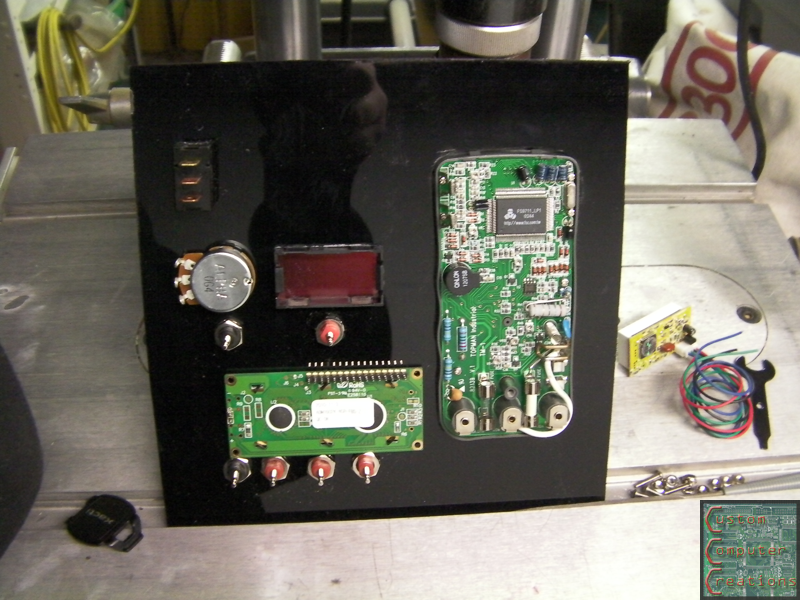
well I'm still using my LCD for the straight monitoring, that secondary LCD will be for a separate 12v line that I will be able to regulate down to 3v or so
Alright so I got some more work done on this thing!
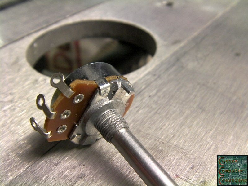
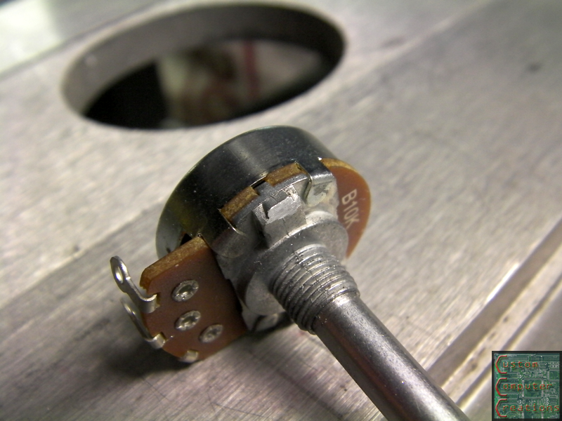
The pot I got for the variable output had 2 problems. First there was this little tab in the way, but that was easily taken care of :D
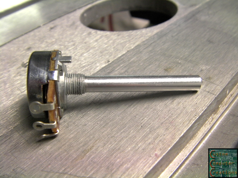
Second, it was WAAAYYY too long, but that was easily taken care of as well :D
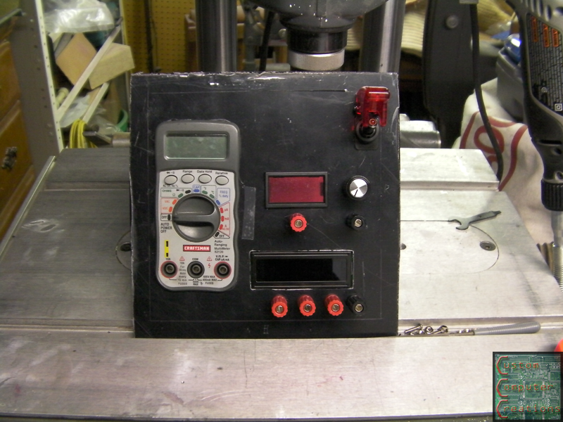
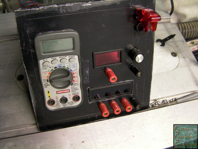
I also got the front panel mostly cutout and parts temporarily installed. All that's left is to cut the openings for the molex's and the little opening for the LED tester :D
That's it for now!
Interesting project SXR. I'm looking at doing something similar but measuring voltage, power, and current. I'm looking at TI's INA219 right now as an option. Still kicking tires and learning. I've got a few ina169's if you want to add current measurement.
How hard was it to dismantle your PSU? Anything to watch out for?
Thanks for the offer, but the SMT package won't work for me for this, I need a through-hole package.
As far as dismantling the PSU goes, it was pretty straightforward. A few screws for the housing and such. The only hard part is the power connector and switch. You either need to cut the housing (like I did) or de-solder all the wires from each one and get them out that way. I figured I didn't need the housing so I just cut it, it made things easier.
Watch out for the caps, make sure not to short them with anything (like a wedding ring) during disassembly :D
Thanks, I'll keep that wedding ring thing in mind :)
Great work so far! I have almost the exact project going on right now. I'm going to have 24v, 12v, 5v, 3.3v, and a variable line. I was also thinking of adding some usb ports for charging/testing usb powered things and a fuse tester. I like the suggestion of an led tester as well so I might have to borrow that idea.
I like the idea of the USB port for testing/charging...I may have to borrow that :D
Update time!
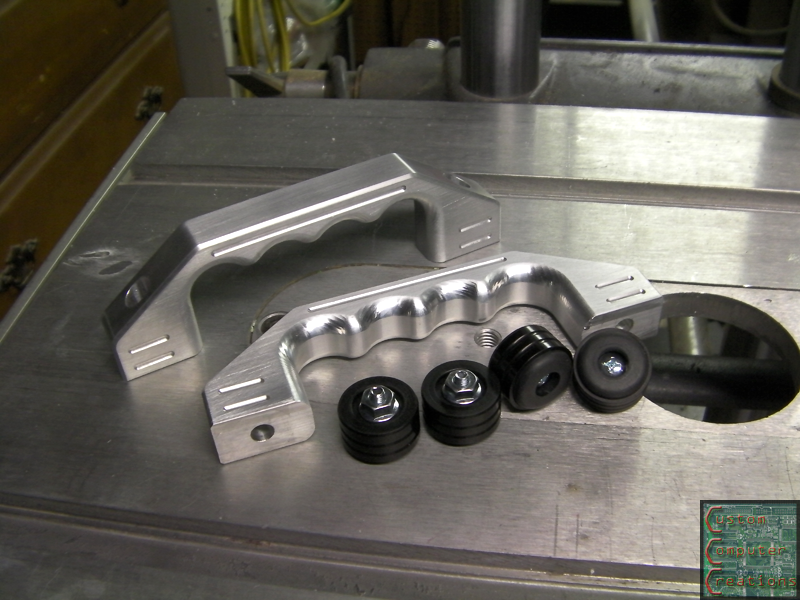
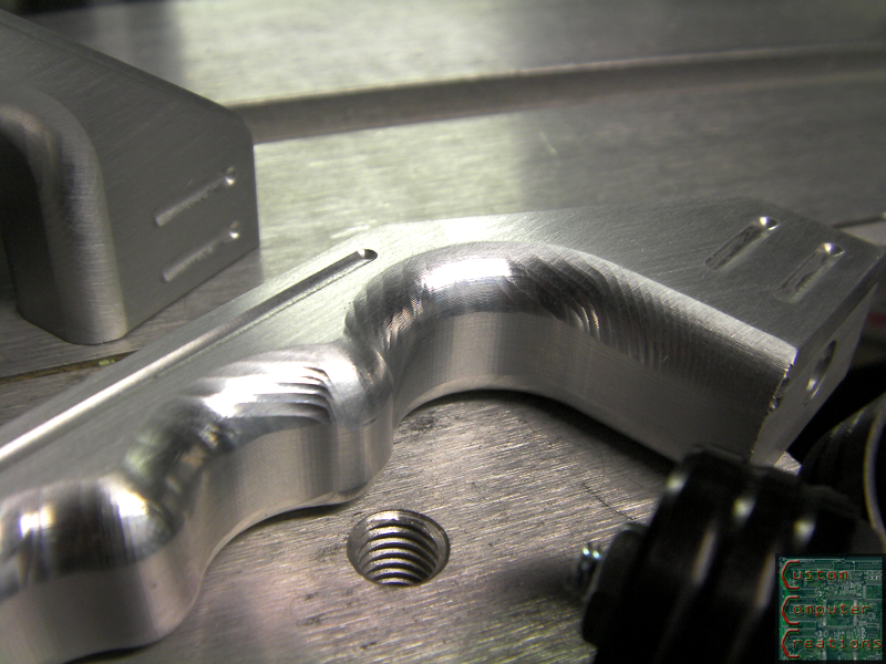
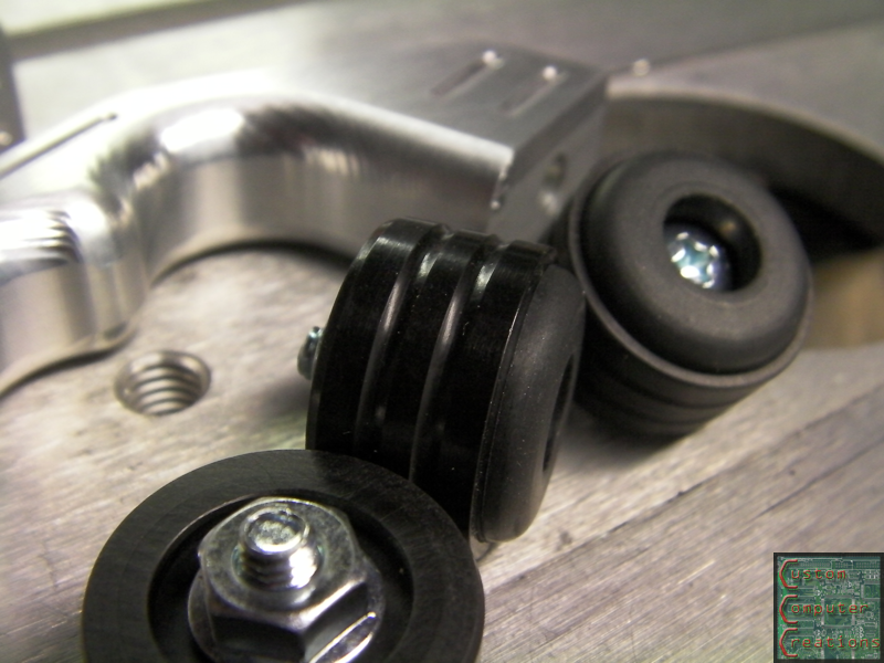
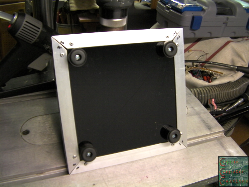
I got these SICK case handles and feet in from MNPCtech!
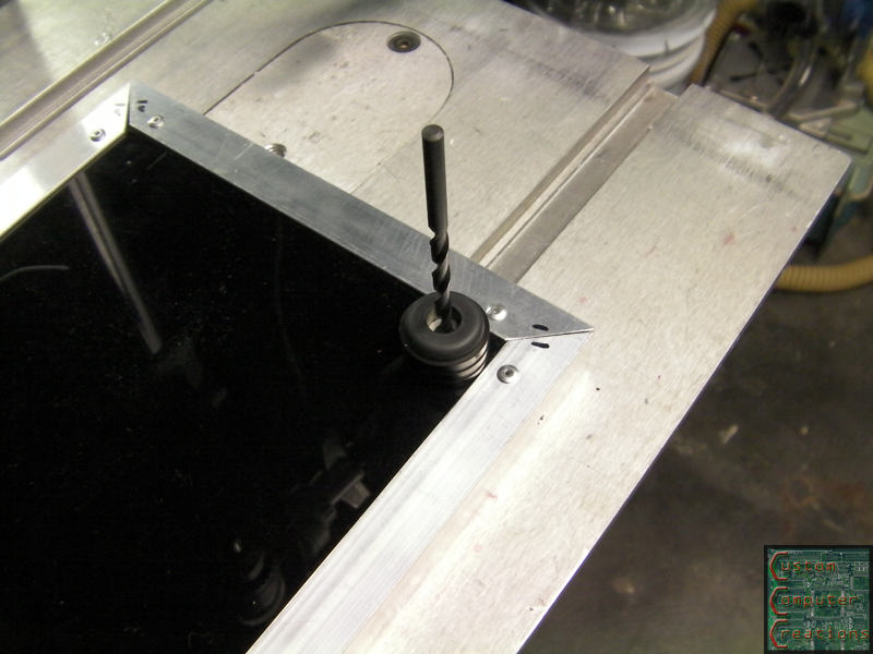
I placed each foot in it's position and marked it with a drill bit, then drilled the holes and mounted the feet.
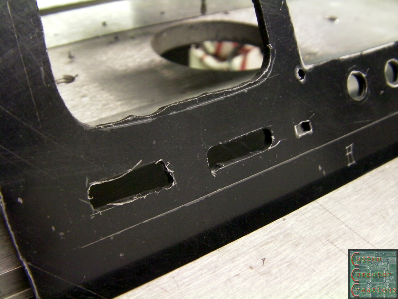
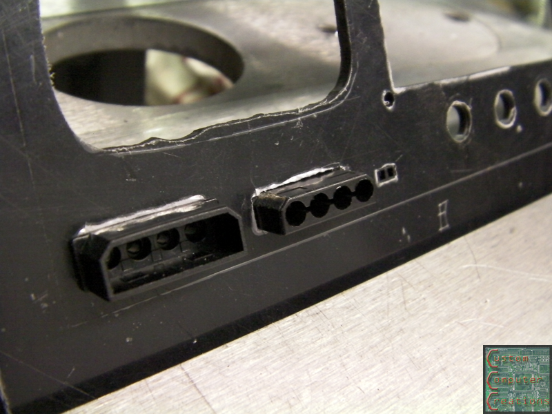
Next I got the rough cutouts for a male and female molex as well as a 2-pin MBB header (for the LED tester) done, then spent some time filing until the pieces fit.
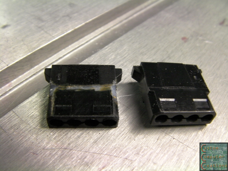
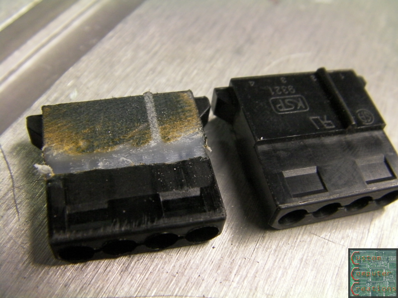
Now I had to modify the male molex so it would go through the panel enough for the pins to properly connect. I also found out, interestingly enough, that they're not made of black plastic!
Now I've got to decide where I'm going to put a USB connector (or two :D), and I've been throwing some design ideas around in photoshop that I'll etch into a blank space on the front. Granted it won't have the ability to be edge-lit, but it should still look sweet :D
Uhm...
Where are you going to get 24V from, Crimson?
AFAIK, the max is 12v in a standard PSU
Even Apples only have 16?/20?V on theirs.
Good progress, tho, SXR