Page 1 of 3 123 LastLast
Results 1 to 10 of 23

Thread: Onyx

  1. #1
    Stupidity feeds my children blueonblack's Avatar
    Join Date
    Feb 2008
    Posts
    2,616

    Default Onyx


    Well, here we go. I've decided to embark upon my first mod. I've been building systems for years now, but always bought the cheapest case available that would work for the job and hid it away somewhere. A couple of months ago I built a new one for myself and used the same old boring generic bargain-bin case I'd had the old guts in. I figured why buy anything cool since I couldn't fit it on my desk to admire anyway? Then I discovered this site, quite by accident, and it changed my whole perception. I then found the Ultra Microfly SFF case with windowed sides and thought I had my answer. I would just buy that and sleeve my cables, add lights and some UV-reactive glitter and all would be well.
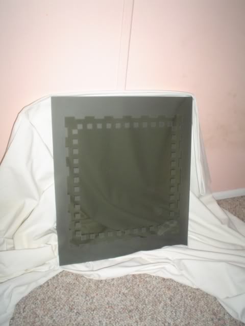
    Not so. This case is extremely cool, but it is TOO SMALL. With two hard drives, two optical drives, an ATX power supply and a 20-pin to 24-pin adaptor cable (the PS came with the bargain-bin case), there is NO room to do anything cool. So....
    I love the cube shape for cases. Just seems the tower is everywhere and I want something different. That's what brought me to the Microfly. But I have yet to find a cube with the space I need and a decent look to it, so I've decided to build my own, from scratch. Lots of firsts here for me: first mod, first opportunity to work with acrylic, first time sharing any work I've done in my shop while it is ongoing. This is obviously also my first worklog, so if I break any rules or violate any traditions, please feel free to let me know. I only hope I don't embarrass myself.
    The case I have in mind will be a cube, as mentioned, designed to fit the available space on my desk, roughly 18 inches on a side, and made entirely of acrylic. Plenty of room, which is good because I will be able to adapt the case to hold future upgrades if needed. None of you know me, so I thought I would throw in a few pics of what I have to work with.

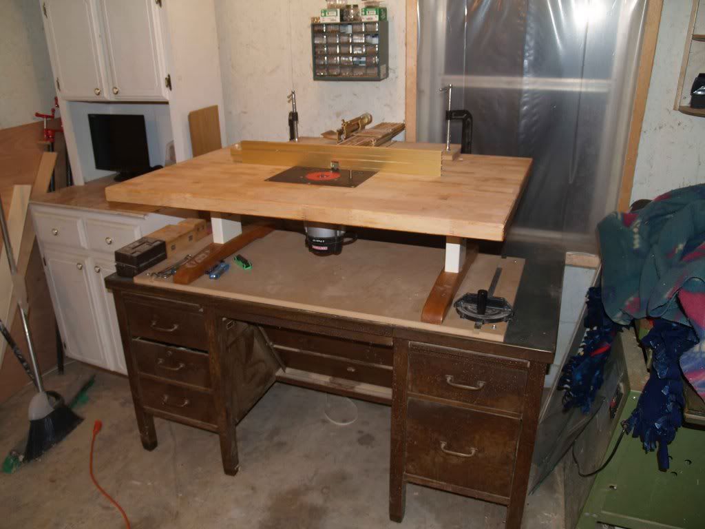
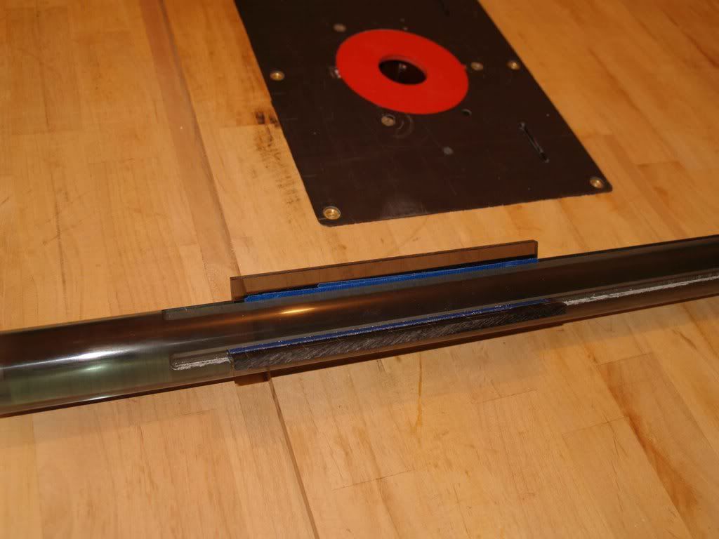
    My new router table. A recent mod of an old maple-topped kitchen table and I absolutely LOVE it. Time to put it to work!


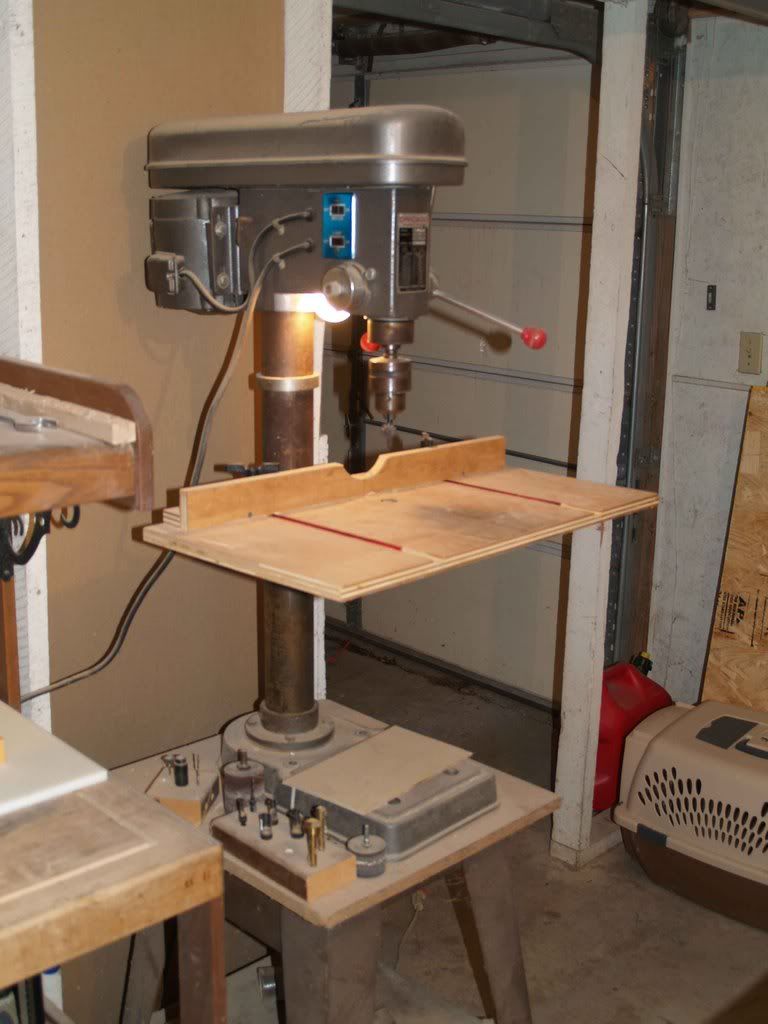
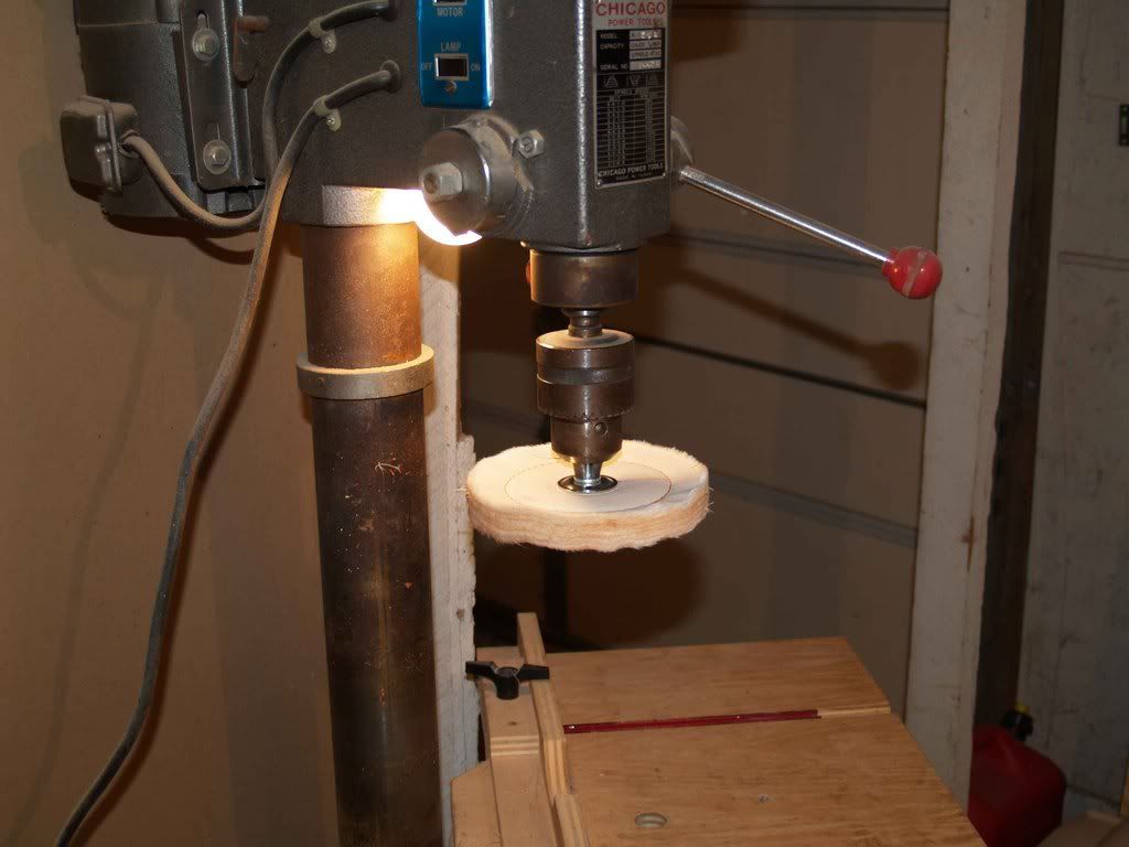
    My grandfather's old Chicago drill press. At least twenty-five years old and still runs true.


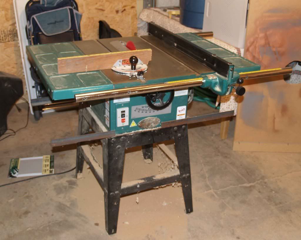
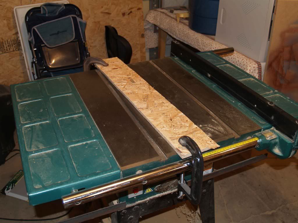
    My table saw. Grizzly rocks!


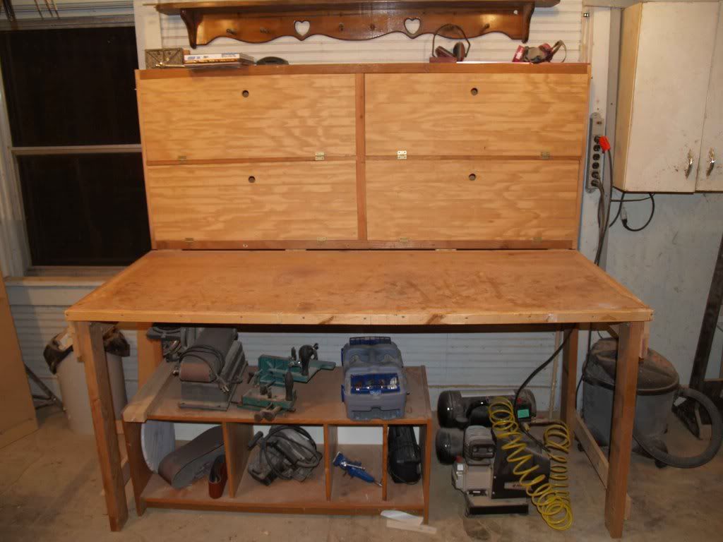
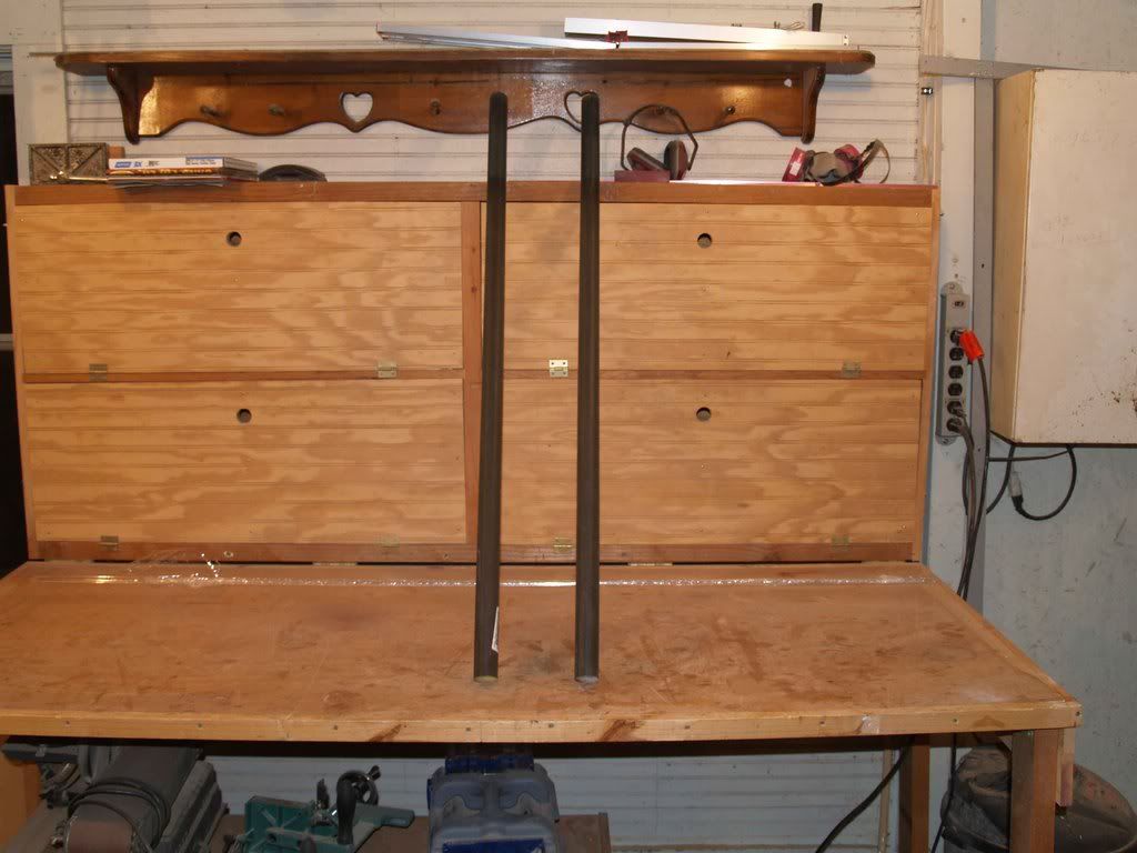
    My homemade workbench, made from scraps and a solid-core door blank.


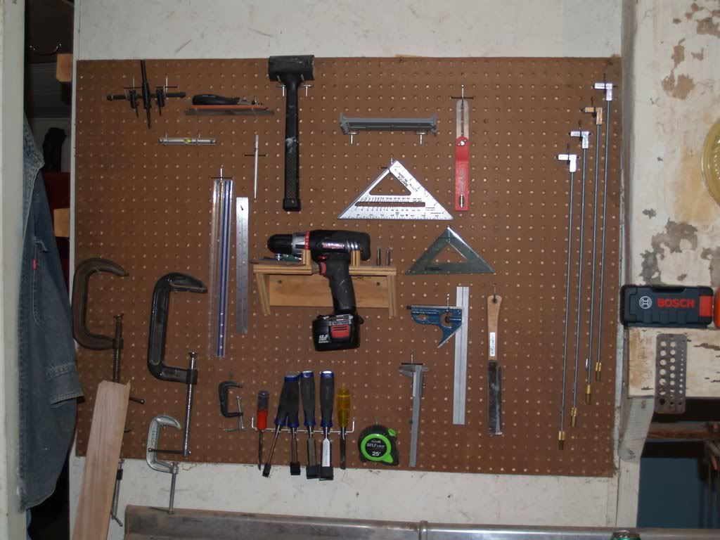
    My wall of most commonly-used layout and hand tools.


    Enough about my workspace, let's talk about this case. Once I decided on acrylic I started doing my homework. As most all of you know, there are 2 kinds of acrylic: cast and extruded. The difference is density, hardness, melting point and price. The design will call for extensive machining of at least five parts so those at the very least have to be cast acrylic, and four of those five are rods, and have to be at least 1 1/2" in diameter and 2 feet long. The other is for the top and needs to be 3/8" at least. Sticker shock!!!!

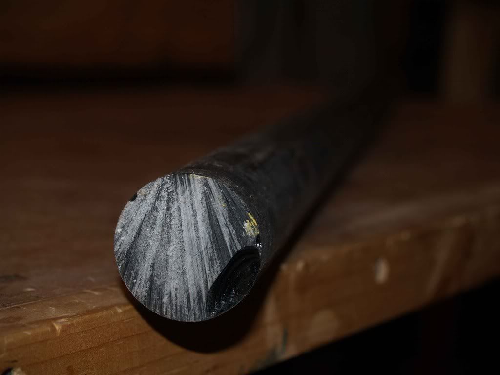
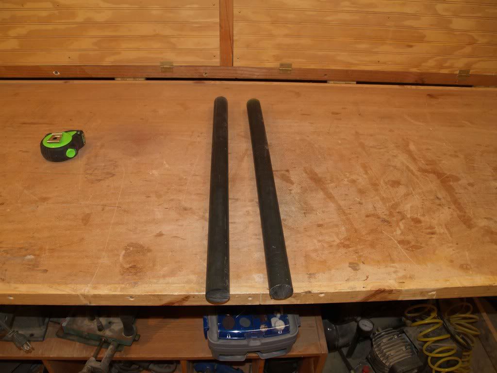
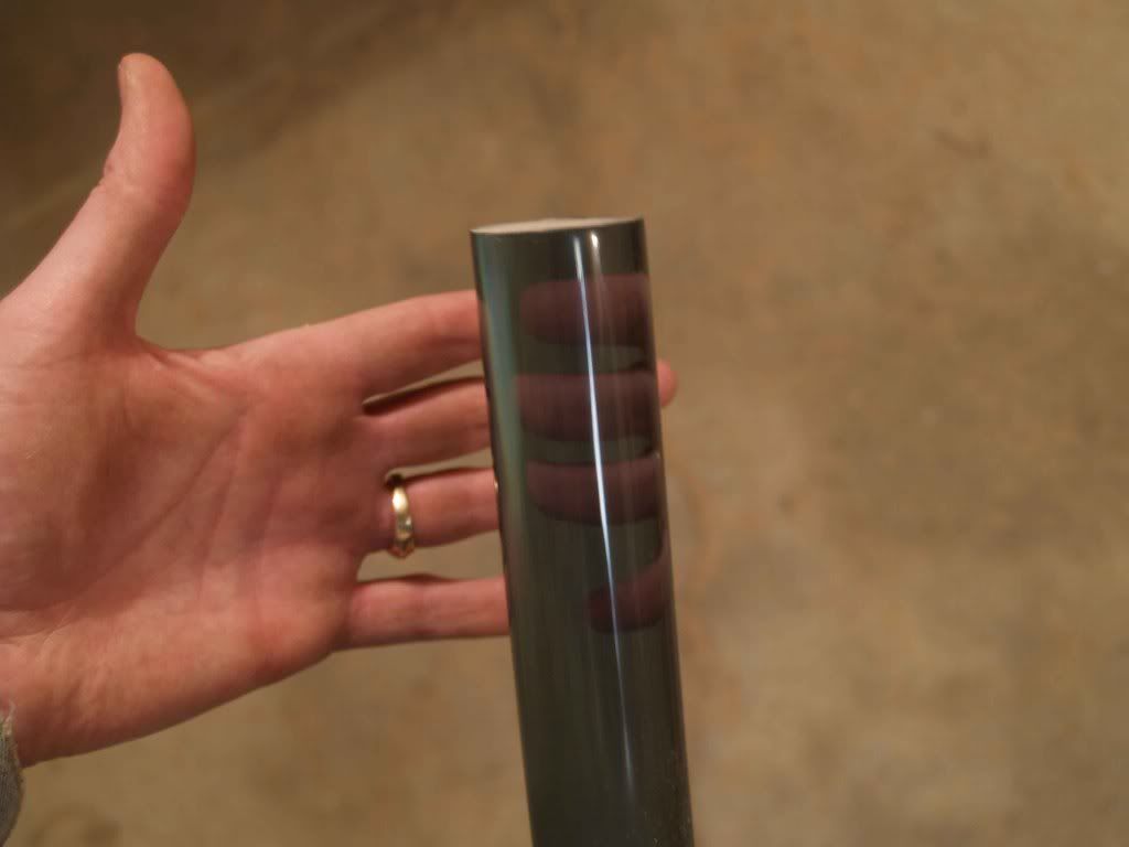
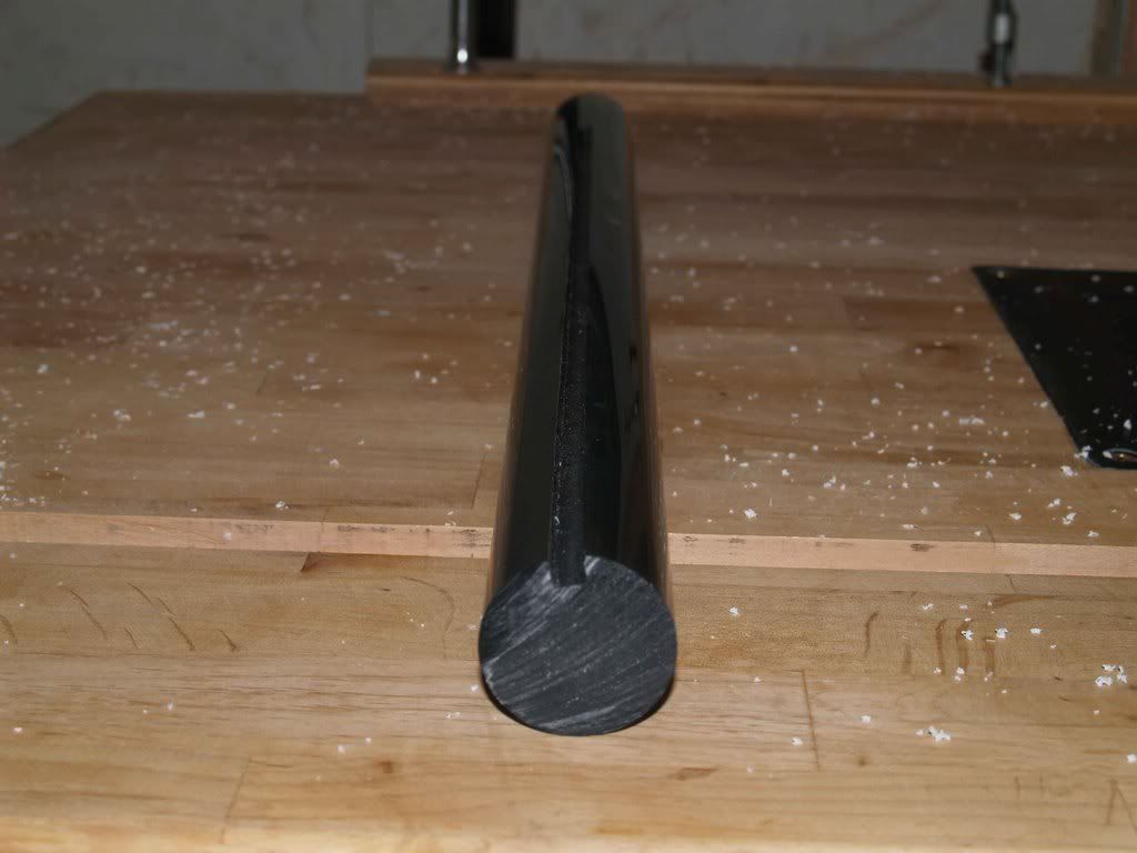
    But the lords of modding were smiling on me today. I'd been kind of down thinking it woud take a LONG time to save the cash to do this thing, with the materials being so high, but I went out to the only two local plastic suppliers we have today and hit the jackpot. The first place happened to have two pieces of drop (scrap) cast sheet, one 1/4" and the other 3/8", and guess what? The 3/8" piece is big enough for my top! While I probably won't have a use for the 1/4" piece, it will be excellent for practice since I've never worked with it before. They offered to order the rod I needed for the tiny price of my left arm and the soul of my next-born child. Down the road I went. The next place didn't have any sheet or any clear cast rod, but they DID have a large bin of colored cast rod that they had ordered for a customer six years ago and was never picked up. They want to get rid of it bad. I didn't want color, but they happened to have two 4-foot pieces if 1 1/2" gray cast rod, and would sell it to me at cost. Normally $19 a foot, I got it for less than $7. Only problem being, it's machine-grade which means it's not polished. I will have to polish it myself, but at that cost I couldn't walk away from it.

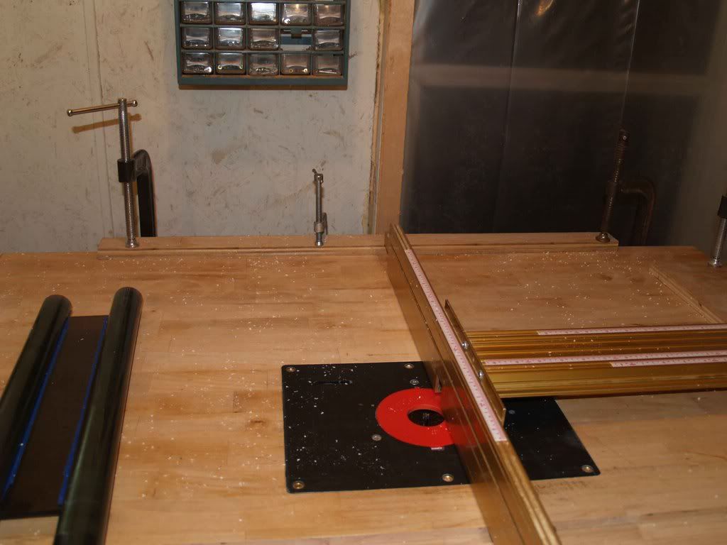
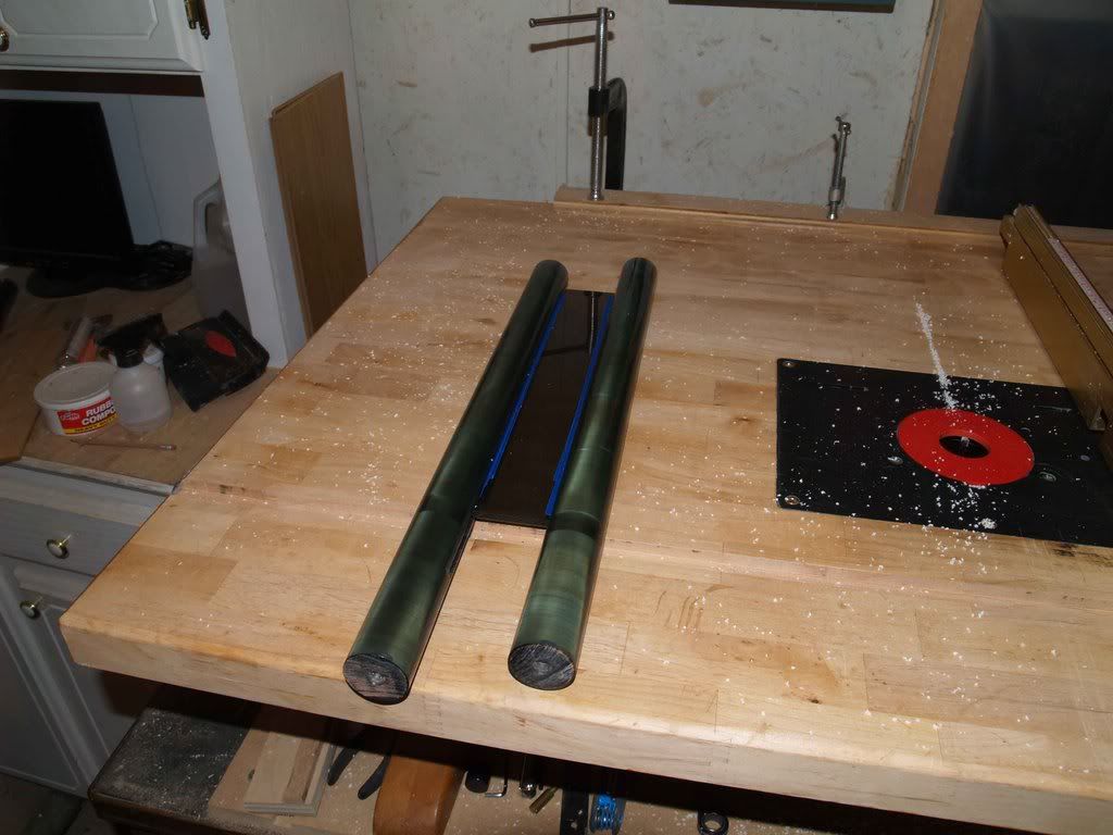
    My 2 new rods (smaller clear extruded rod laying on the bench behind them for internal work).


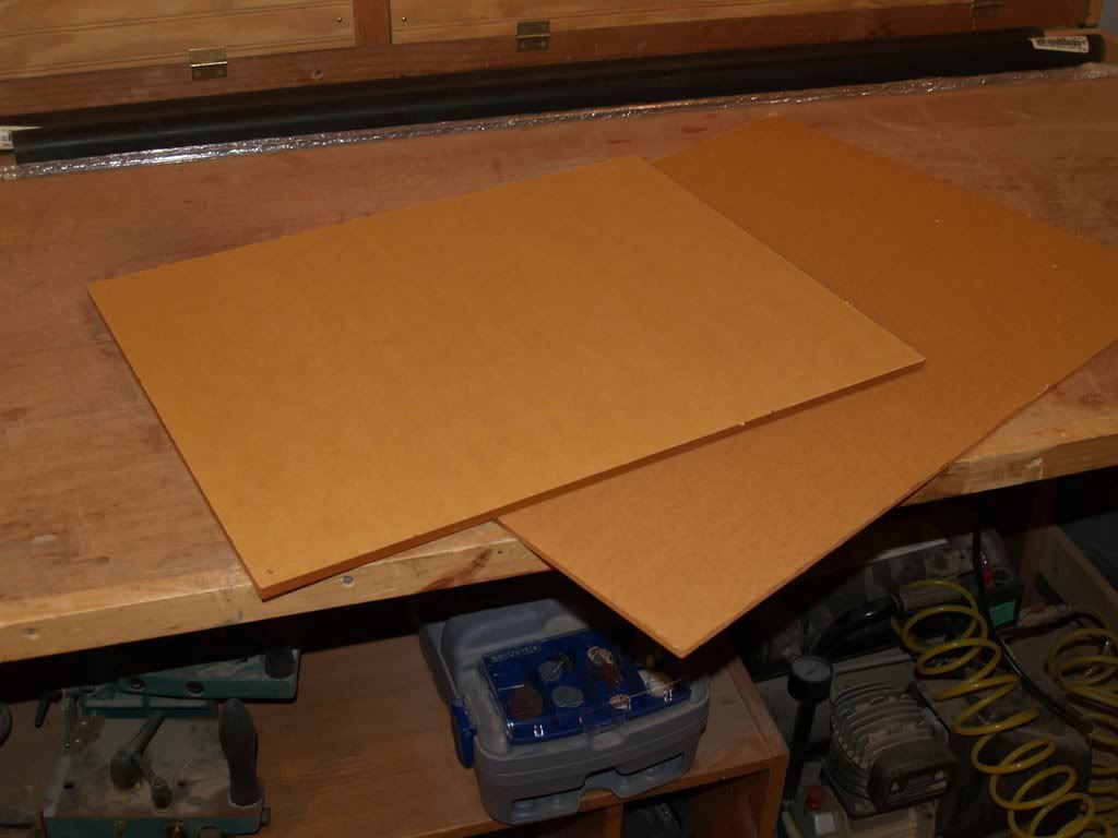
    My scrap sheet, a mere $20 for both of them!


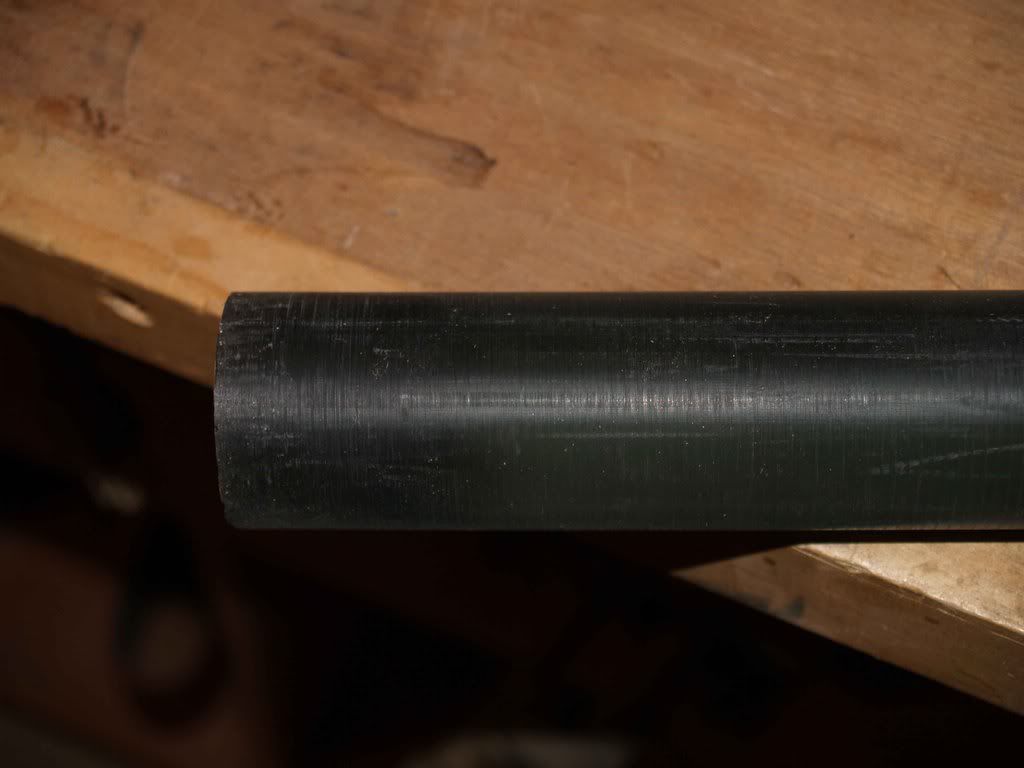
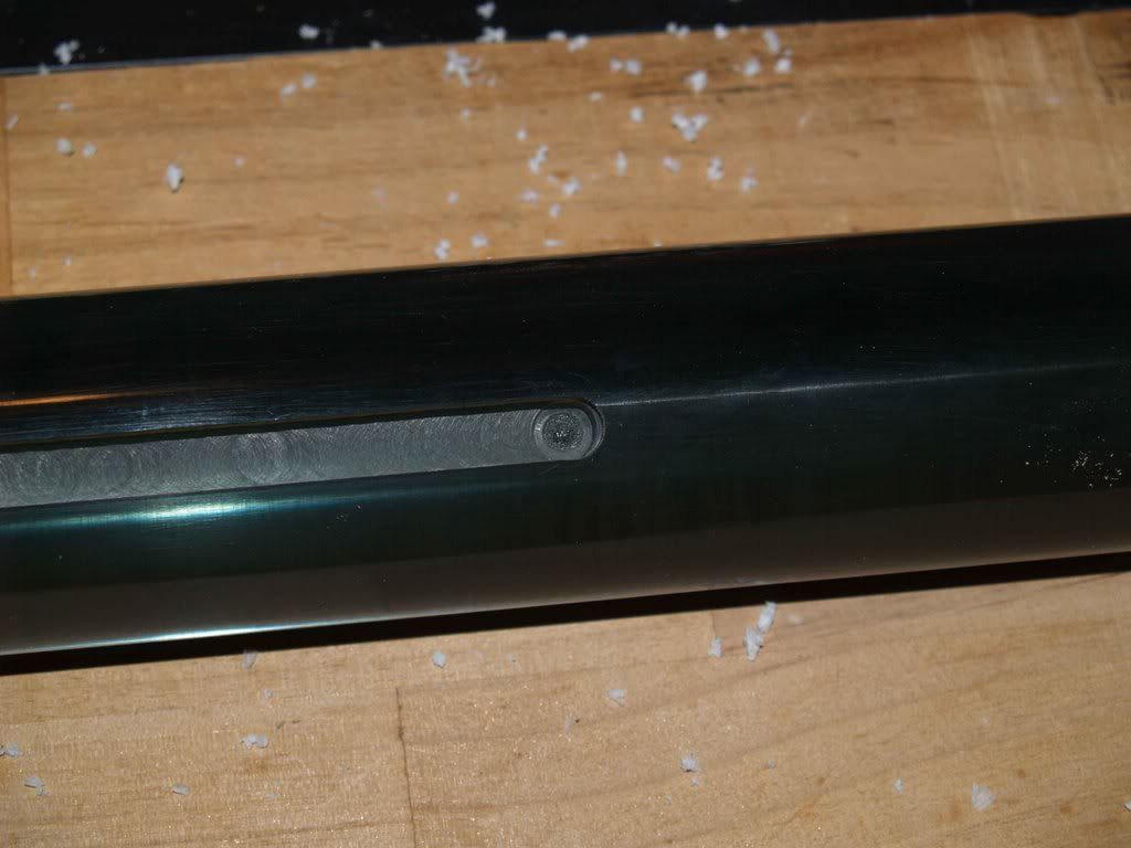
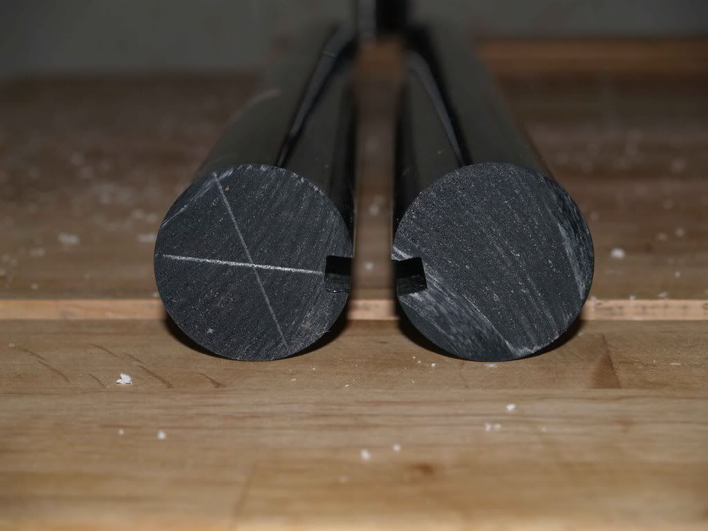
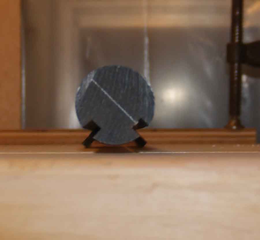
    Closeup of the rod, as you can see, it is FAR from polished.


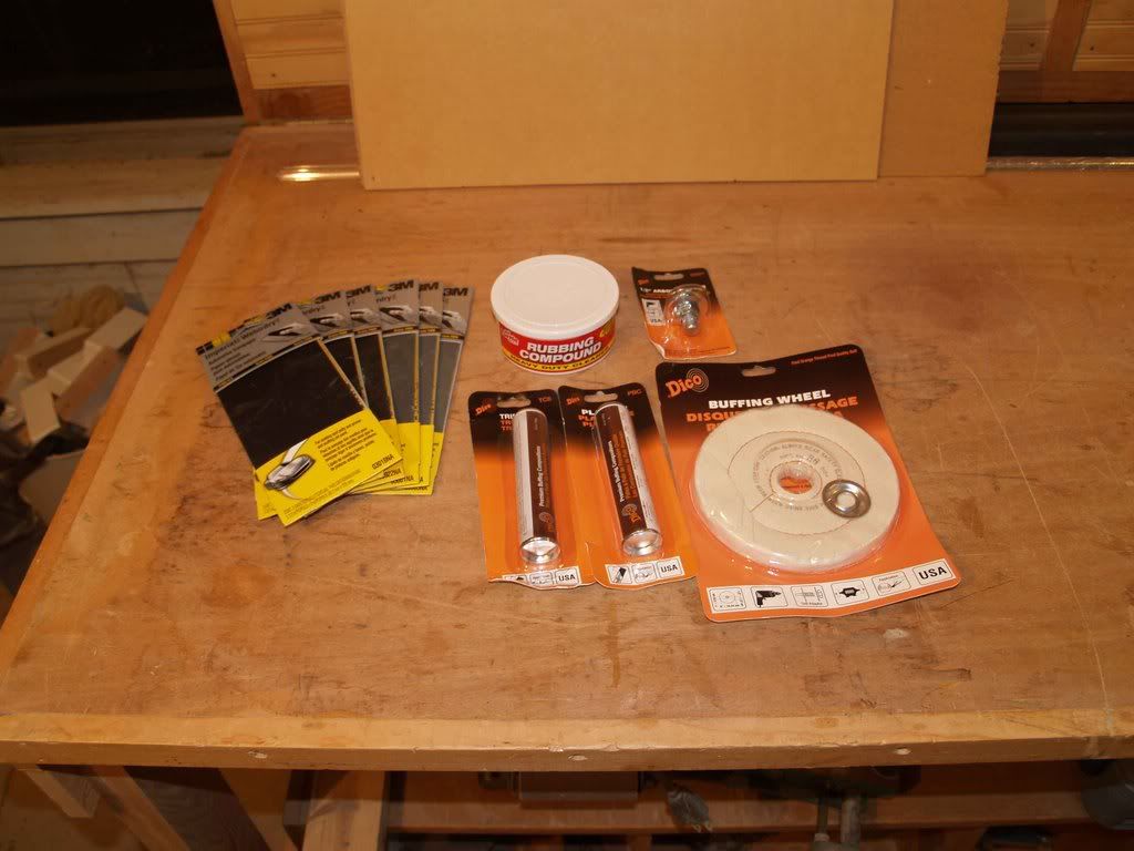
    Some sanding and polishing supplies I was told I would need:


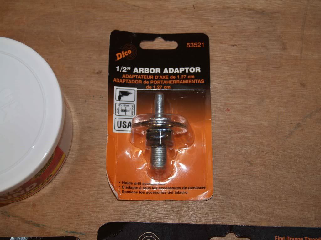
    I do not have a bench grinder, but can anyone tell me why I can't use this adaptor to put buffing wheels in my drill press?


    Some problems I foresee with this scratchbuild:
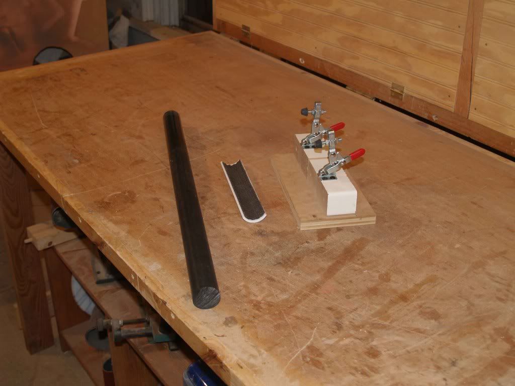
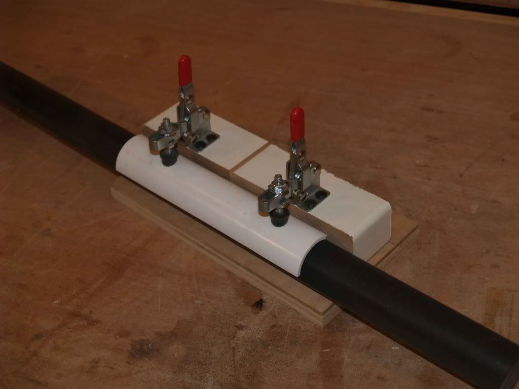
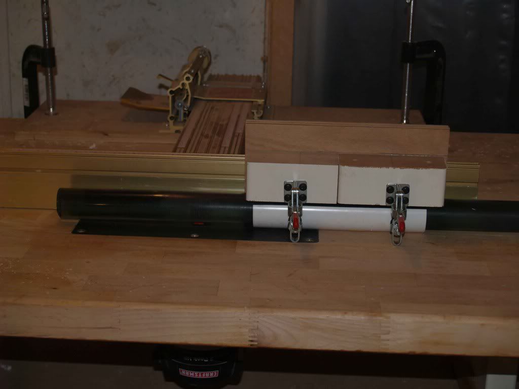
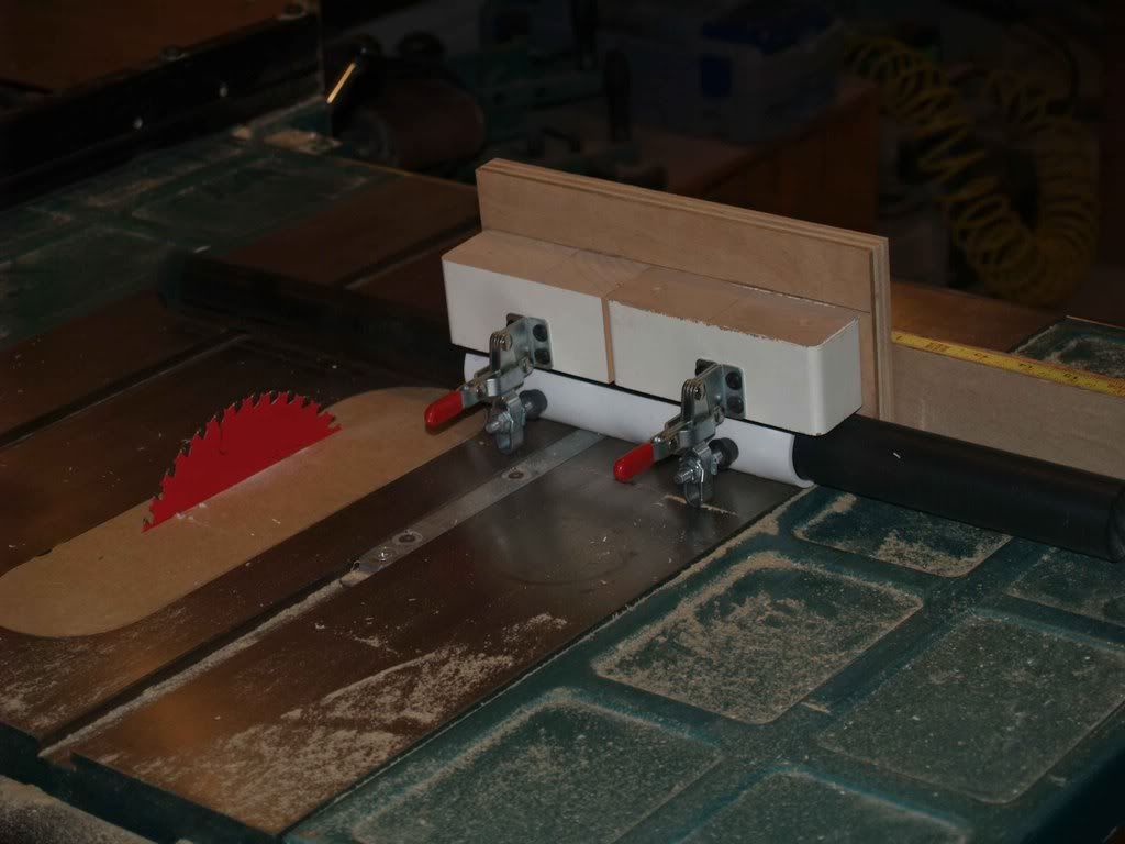
    Polishing that rod. Would be easy as pie of I had a lathe, but I don't. I could probably sand/polish it laterally and have it end up nice, but it would be much easier and a LOT faster if I could get it to spin. We will see.

    Machining the rod. Holding perfectly round and polished material perfectly square to a cutting blade on a flat surface while moving. Without scratching it. Will have to build at least one jig for this, likely three or more.

    Edge-polishing the top. The edges of the top sheet will be rounded into a half-circle with a router and will have to be polished to a glass clarity since the viewer will be looking right at it.

    Making the flat sheets match the newly-purchased gray-tinted rods. Window tinting film, perhaps?

    Anyway, more news as it happens, cutting and polishing the rod are up next. Wish me luck, I won't find a bargain like this again.
    ________
    Marijuana Dispensaries
    Last edited by blueonblack; 02-24-2011 at 02:37 PM.

  2. #2
    Stupidity feeds my children blueonblack's Avatar
    Join Date
    Feb 2008
    Posts
    2,616

    Default Update

    Got it started.

    The first thing I needed that I didn't have was a zero-clearance insert for my table saw. I could either go buy one for $25 (I actually did that once, doh!), or I could take a scrap piece if 1/2" MDF and make one myself. For those who don't know, this is an insert made specfically for an individual saw blade, and when done it will have, you guessed it, zero clearance around the blade. Helps reduce chipout and is crucial for smaller parts.

    Here is the stock insert from my saw alongside the scrap I will use.


    Traced the outline onto the scrap in order to cut it down closer to size...


    Now to use what is possibly the greatest invention of the 20th century: double-sided tape! Apply to the scrap, then press the insert onto it, inside the pattern you drew earlier.


    To make this cut you need a flush-cut bearing-guided bit. This one is a shearing bit, meaning that the cutting blade sits at an angle so that it has more of a cutting action than a chipping action. Important with materials like MDF. And acrylic, I am told.


    Put the work on the table MDF-side down and raise the bit so that the bearing rolls along the factory insert. Pass it along the bit all the way around, pry it apart gently and...


    Cool, it's cut to size. But it's not the correct thickness, so it will sit lower than the table top. Not good. Just about all table saws will have small horizontal areas under the insert for leveling screws:


    All we have to do is screw short screws into our MDF where these leveling areas are and use them to level the insert. Ok, so I got it to fit nice and snug and level. Clamped piece of scrap plywood over the insert...


    And SLOWLY raised the blade through the whole thing. Lift off the plywood and presto, perfect fit.


    I have read in more than one place that to cut acrylic you need a special saw blade. Triple chip, certain degree of rake blah blah yadda yadda. Quite honestly, I can't afford one. What you see here is a Freud Diablo 7 1/4" 40-tooth combination blade. I've been woodworking for a while now and have tried a great many blades, but this little miracle is the best ever. Looks a little funny sitting in a saw made for a 10" blade, but what the heck? The arbor hole is the same, it runs quieter, is less likely to bind in the work, cuts smoother (REAL smooth), and is thinner than any 10" blade you'll find anywhere, thereby making the cuts easier and producing half the waste. These are $15 at my local Home Depot and I can't say enough good things about them. I have to cut this 4-foot piece of acrylic rod in half now, so let's see how it does...


    Not bad at all! No chipping or melting, just the unavoidable machine marks but even those are so faint you can barely feel them.

    Now the part I've been dreading. This rod is dull. It looks like a piece off of a stealth bomber it's so dull. My initial plan to tap the end and use a bolt to chuck it into my drill press didn't work #@^&@!!!! The distance from the chuck to the base of my press is less than 2 feet. I couldn't figure out any other way to make this rod spin so here we go the old fashioned way. 220-grit wet/dry sandpaper to get out the milling marks (did you SEE those marks in the pic above??). Arm is tired already. Move up to 320, then 400, then 600, then 800, then 1000 with rubbing compound. Almost there. I really don't want to chuck this rod in a vise of any kind, so I needed a way to buff it while holding it.


    Worked pretty well:


    Only polished a small test area on this rod to see if it would work. Short answer is yes it will. But there's four times that much left on this rod, and three MORE rods after that! I have GOT to find an easier way.

    Next up, going to try my hand at machining and polishing the edge of some of this thicker sheet I got for the top of the case. Until then...
    ________
    F2004
    Last edited by blueonblack; 02-24-2011 at 02:38 PM.

  3. #3
    Stupidity feeds my children blueonblack's Avatar
    Join Date
    Feb 2008
    Posts
    2,616

    Default Update: Rod-holding jig

    Finally figured out how to hold this rod still and level while cutting it, thought I would share the steps in case it might help anyone else in the future. Here is the jig:


    Those lever clamps were left over from another jig I made several years ago and used once, had forgotten all about them. You can get them at Grizzly.com for about $10. You can see I mounted then on some scrap 2x6 and mounted THAT onto a piece of flat straight 3/4" plywood. Now I needed some way to apply the pressure from the two rubber pads on the clamps evenly to the rod. I cut a section out of a short piece of 1 1/2" PVC pipe (same size as the rod), applied double-sided tape to the inside of it, and to that I stuck this rubber sheet product that is sold as a shelf liner or drawer liner for tool boxes. Also sells as a non-slip routing/sanding pad at some wood stores.


    Here are the three pieces together...


    And here's the final product. The pipe spreads the clamping force of the 2 lever clamps across the rod, while the rubber liner keeps it from slipping. A little adjustment to the clamps and here we go.


    I'll have to machine slots in these rods lengthwise, so here is how it will work on the router fence.


    And it also works on the table saw.


    Took me a while, burned several hours last night with no results (didn't have the pipe, that was the key) but it turned out just fine. Hope it helps someone in the future.
    ________
    VAPOLUTION
    Last edited by blueonblack; 02-24-2011 at 02:38 PM.

  4. #4
    Stupidity feeds my children blueonblack's Avatar
    Join Date
    Feb 2008
    Posts
    2,616

    Default Question, any ideas?

    My original design called for circuit patterns to be laid out on the sides of the case in vinyl, with the center open to view as a window. I still love the circuit pattern option (like on a printed circuit board) but the vinyl's not going to work for me. I've decided to tackle another first and etch the plexi. Lay out the circuit pattern in vinyl or paper or tape or whatever and etch it so that the outer rim of the side is frosted and the circuit lines are clear. Have a couple of local vinyl shops that could probably cut the mask for me if I could bring them a pattern, but none of the software I have seems suitable for this and I can't draw them by hand. Can anyone recommend a way to produce this circuit effect on a computer so I can make this pattern? Also, can anyone recommend an etching agent that will etch plexi but not vinyl?

    Solved one of the above problems today and just ordered the rest of the flat plexi tinted the same as the rod. Still using the clear scrap, the thinner piece will be the bottom (since you'll barely see it anyway) and the thicker one will be the top. Wanted the top tinted also but for a piece like the scrap I got for $10 they want at least $65. I can always cut a new top later.
    ________
    Launch Box
    Last edited by blueonblack; 02-24-2011 at 02:38 PM.

  5. #5
    Stupidity feeds my children blueonblack's Avatar
    Join Date
    Feb 2008
    Posts
    2,616

    Default Re: Project: Onyx

    Quote Originally Posted by OvRiDe View Post
    Quick question.. When you use the jig to cut the acrylic rod on the table saw, do you use a regular toothed saw blade or one of those friction blades?

    Will be using the same Diablo blade in the above pics for all of my table saw work on this project. Those things are absolute magic! Turns out I have to buy a special router bit to cut my slots since 1/4" plexi is NOT 1/4". It's 7/32" and I don't have a 7/32" router bit. Most people don't. That's another $25. This is getting expensive.
    ________
    JAILBROKEN
    Last edited by blueonblack; 02-24-2011 at 02:38 PM.

  6. #6
    Stupidity feeds my children blueonblack's Avatar
    Join Date
    Feb 2008
    Posts
    2,616

    Default More parts!

    Well, I got more parts in. Found four pieces of 1/4" gray tinted plexi to match my rods for $20 each, cell cast acrylic, very nice stuff and it's actually 1/4" thick! Have enough of that for the sides so I'm done buying the sheet material.

    Also got what I THINK is all the rod I will need for the internal support structure. I've decided not to use any factory-made supports like drive cages or power supply bays. Going to make my own support network out of plexi rod.

    Power supplies have arrived, have UV lamps, temperature probe and Bulgin switch in route now. Scored myself a sweet cordless butane soldering iron and am about to start a 4-day weekend. Let's get some work done!
    ________
    Ford focus picture
    Last edited by blueonblack; 02-24-2011 at 02:38 PM.

  7. #7
    Stupidity feeds my children blueonblack's Avatar
    Join Date
    Feb 2008
    Posts
    2,616

    Default Side panels done!

    Well, I had planned to do this with a printed circuit pattern, but honestly, that turned out to be more trouble than it was worth. I think this pattern turned out nicely though. Both side panels are now complete and ready to fit.


    ________
    Vermont marijuana dispensaries
    Last edited by blueonblack; 02-24-2011 at 02:39 PM.

  8. #8
    Stupidity feeds my children blueonblack's Avatar
    Join Date
    Feb 2008
    Posts
    2,616

    Default Update - Finally some progress!!

    Finally got back to work on this thing, all my parts are in, had a heck of a time finding the tools to machine these large acrylic rods but it's done!

    I'll be using four of these vertically as the main support for the case, with a sheet of 1/4" acrylic glued inside a groove in the side of each one. Needless to say, the grooves had to be perfect. Here's a shot of one of them with a single groove.


    These grooves couldn't go all the way through the rod, as the tops are going to be visible and polished, so I had to set up a stop block before cutting any of them so they would all be exactly the same length.


    The end of one groove:


    One groove was pretty easy really, but the other groove on each column had to be exactly 90 degrees to the other, since they are corners. How to do that? Found a simple solution:


    Set two grooves side by side, connect them with a narrow piece of scrap:


    And bingo. Leave them connected like that and run them over the router, the groove that's cut on the bottom is a perfect 90 to the one on the side.

    All done:


    Now there also have to be short grooves *across* the columns for the top and bottom pieces. And they have to be perfectly 45 degrees to the two grooves I already cut. Same method:


    Hook two *equally sized* pieces of scrap into the two grooves and set the rod on these pieces. Automatically sets the angle perfectly to 45 to the router bit.

    This is a rather poor shot of the front piece with the layout for the holes on it. Ran out of time to actually cut them tonight.


    I did, however, get the columns and all four sides put together loosely just to see what this thing will look like. I like it.


    And I just had to lay some of my UV tubes in there to see if they were going to shine brightly enough through the tinted acrylic. The picture is awful, I know, but it looks like the lights will work. I have more coming anyway.


    That all for this week, will start cutting the top and bottom next week, finish designing the inner support structure and hopefully get some components in there!
    ________
    REVIEW VAPORIZER
    Last edited by blueonblack; 02-24-2011 at 02:39 PM.

  9. #9
    Stupidity feeds my children blueonblack's Avatar
    Join Date
    Feb 2008
    Posts
    2,616

    Default Update: 3/13

    Finally got busy again, last night of my 5-day weekend. Not going as quickly as I would like (of course), but it's going.


    Got the front panel cut out:


    I decided I didn't want to look inside the machine from the front panel, so I bought some Krylon Fusion in satin black and painted the inside of it.


    Got my plasma ball apart, did some testing on it (only fried one circuit, woo hoo!). Discovered that even though it runs on 12V DC the little coil in there steps that up considerably. (Forgive me my electronics ignorance, but this just seems to be how I learn.) First clue was the tremendous shock I got off it, then the purple arc of electricity that followed my test lead off of the top electrode when I checked it. Be careful!


    I've also decided that I cannot in good conscience build this thing and have to look at the dull black surface of a stock card reader bay either.


    So I cut my own.


    Lots of polishing yet to do , plus laying out the rear panel and cutting it and drilling and threading support rod before case assembly can begin.
    ________
    Ferrari Gg50 Specifications
    Last edited by blueonblack; 02-24-2011 at 02:39 PM.

  10. #10
    Stupidity feeds my children blueonblack's Avatar
    Join Date
    Feb 2008
    Posts
    2,616

    Default Detail on side panel

    It was suggested to me that I show a little more detail on the etching I did on the side panels. As you can see from the pic, I used a product from Plasti-kote that simulates frosted glass. I had my doubts at first, but the results are excellent. Perfectly even coverage, and you can control the amount of "frosting" you want on your acrylic. Highly recommended stuff!


    ________
    GENETICALLY MODIFIED FOOD
    Last edited by blueonblack; 02-24-2011 at 02:39 PM.

Posting Permissions

  • You may not post new threads
  • You may not post replies
  • You may not post attachments
  • You may not edit your posts
  •