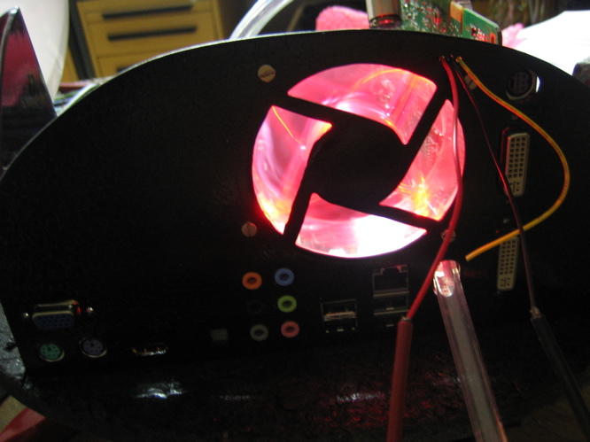
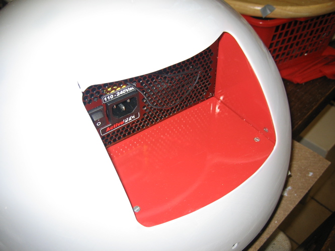
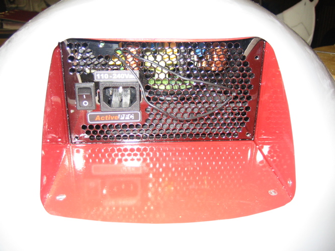
I have to admit: I did it again... Another version of the backplate. Had to make a new one after I noticed I drilled two holes much too big But this time it's perfect. I also cut the holes for the fan:
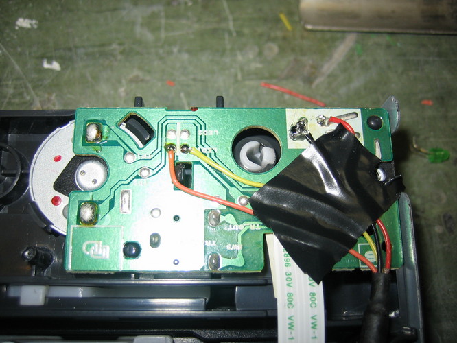
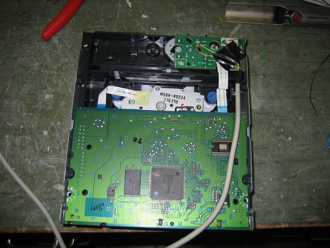
My modding-time was short, so I only had time for a quick change on my DVD. Removed the LED and soldered on an external connector for LED and Eject button. This will be triggered by the controller board only when the visor is open.
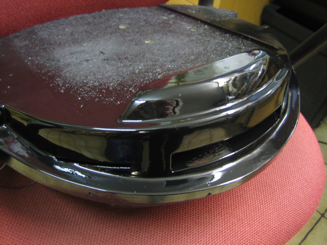
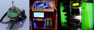
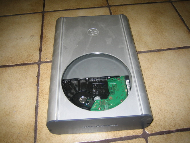
BTW: I found the next modding target It's the packaging of an old Motorola mobile phone. The cage is made of aluminium and it already has a nice window. That would be perfect for an external DVD where you could watch the disk spinning...
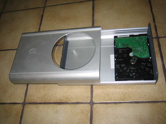
My only problem: I don't need an external DVD Rom. What I have lying around are three 250GB harddrives. So I think I will make an external USB drive case for two drives from this, with a switch, so one can toggle the active drive.
I hope I can do this by simply switching the power of the IDE drives and connect both (master-)drives to a simple IDE2USB converter...
Damn! I almost forgot the video I took of my work on the backplate...
So, here it is: What you see is an ordinary drillbit for big holes and the drill press on top speed. Cuts through smooth like butter.
Not a single comment on that nice Motorola box?!
Perhaps on this update: I started building a Power / Reset switch wich will be placed inside the right foot on the same height as the fingerprint reader in the left foot.
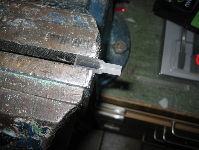
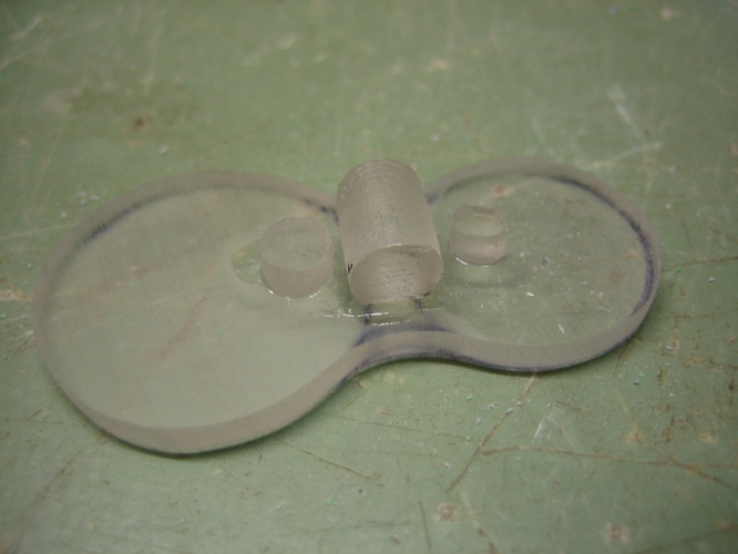
First piece is an axis with one flatend side:
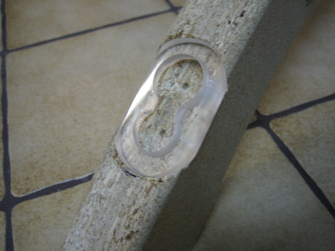
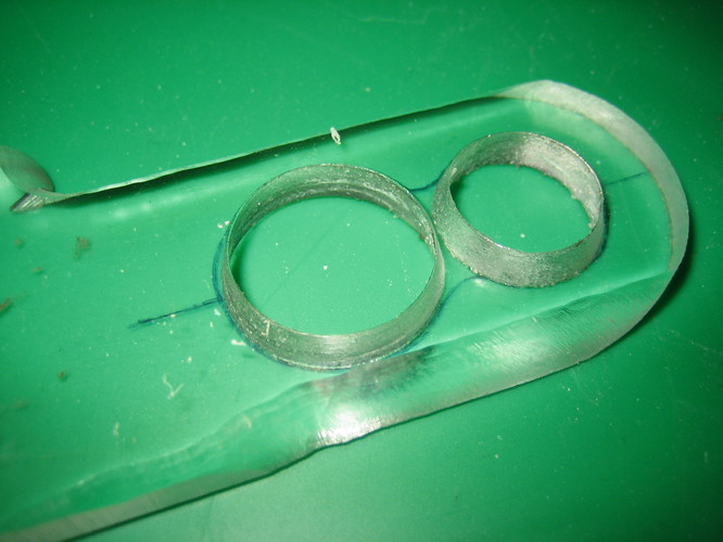
The axis and two tiny spacers are glued on the actual switchplate which has the form of an 8. One big circle for Power and the smaller one for Reset. The spacers will push on the switches.
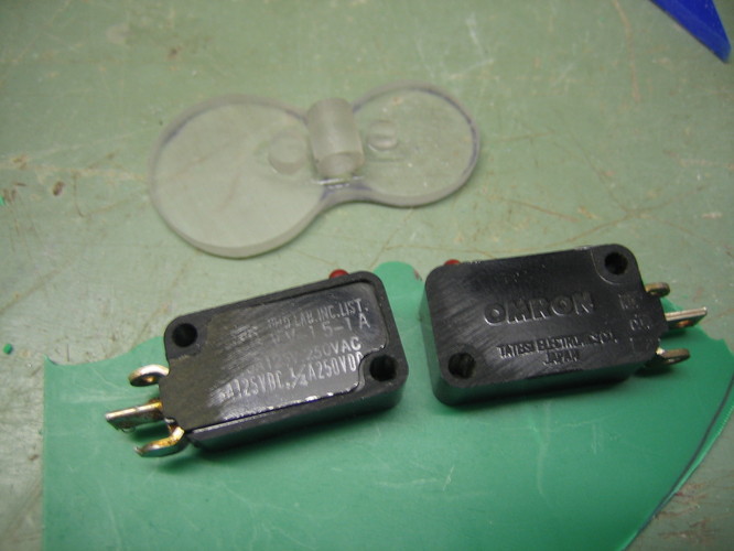
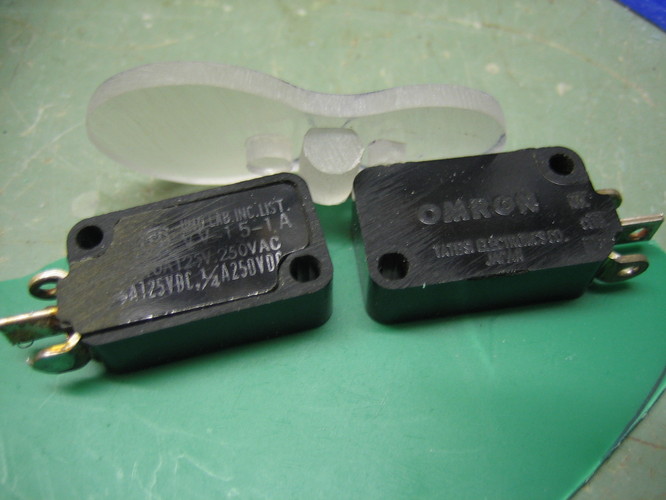
These are two microswitches on a plastic sheet. The bump between the switches will be the support for the axis. I will add the another sheet on top later.
If everything works the way I suppose it to, the springs in the microswitches will hold the plate leveled.
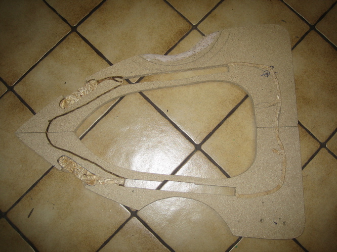
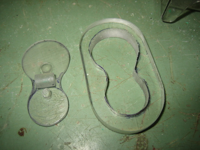
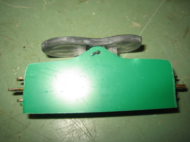
This piece will be the enclosure of the switch-plate.
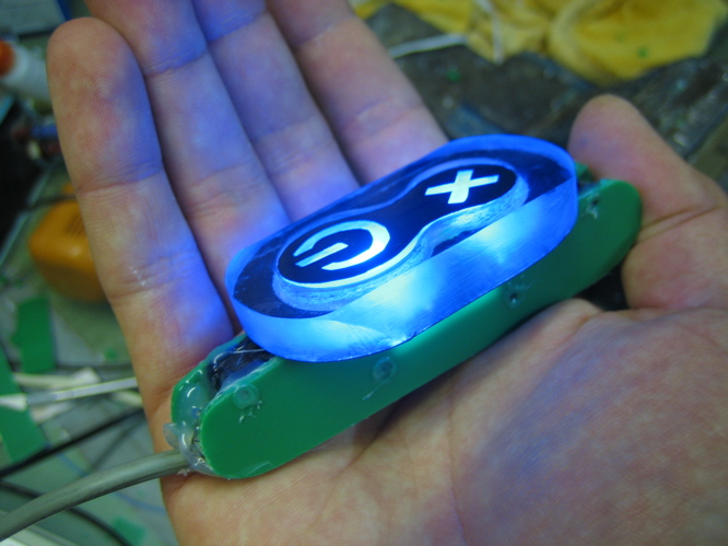
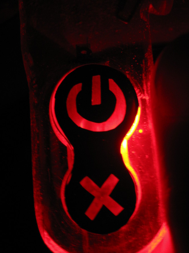
This stuff is still in beta-stadium but I hope it will look nice when polished and illuminated (:
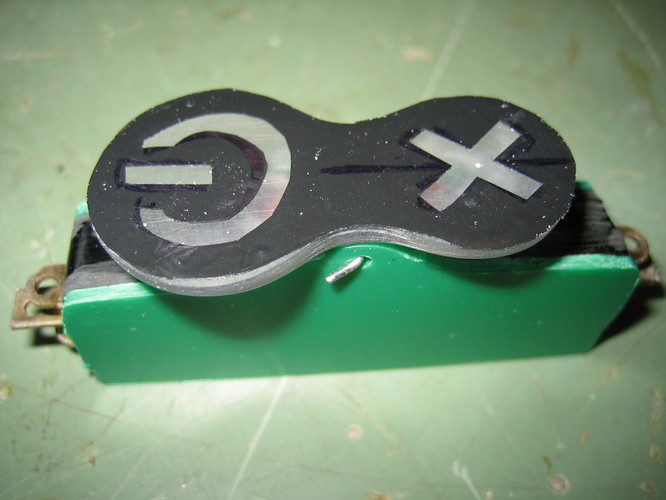
Thank you p0Pe! The switch still needs a lot more sanding but it's now out of beta stadium and got a "proof of concept"
The black foil will of course be replaced by an exact cutout of the symbols!
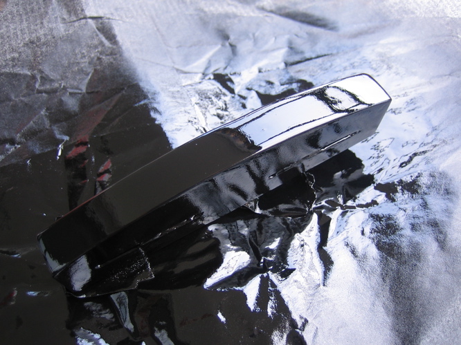
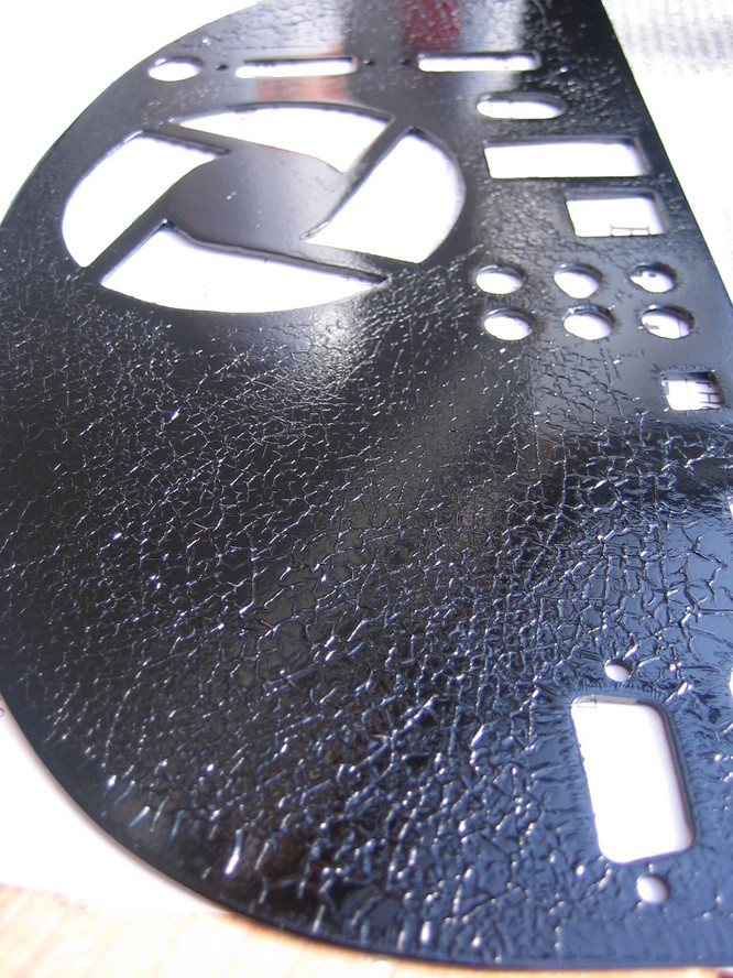
The weather today was quite nice here in Germany, so I added the last coat of paint to the backplate:
Don't ask, how I did that special fx... I simply sprayed on the black paint and it crystalized imidiately. The effect looked nice to me, so I added a clear coat and finished the third try of the backplate finally...
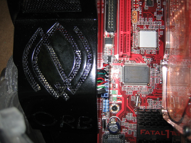
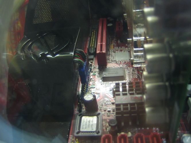
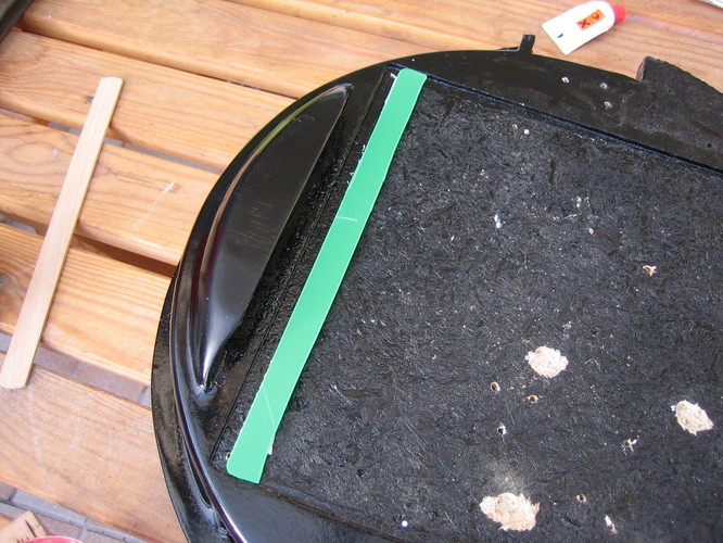
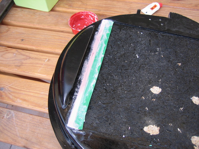
I also modded the Orbs base. As the MoBo moved backwards about 6mm because of the GeForce, I had to fill the gap in the MoBo pit. For that I cut out a stripe of plastic and used it as a form for some filler (so the green stuff will be removed):
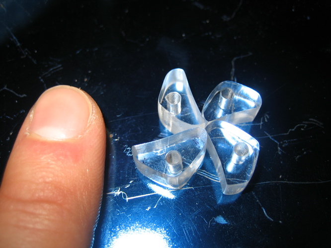
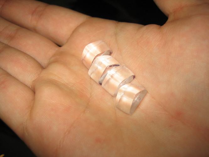
And from the "bits and pieces" section: The mounting pieces for my self made fan:
Watch out for the next update. Hopefully with some more impressive pics of the whole project and not only of some small parts
YIIIEHAAA! Is this my case?? In a Modcast? Really?
What a stunning job, Froop, Thank you so much! *showingthevidtoeverybody*
This video definitely will be my screensafer on the DCMM competition.
I think now I have to put the Haro Mod aside and focus on the Orb again
Wow, one more time on the Frontpage! Thanx a lot TBCS! This deserves an update:
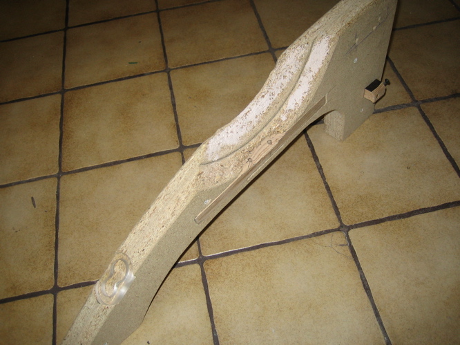
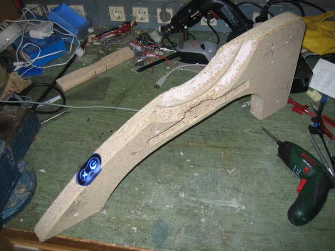
After almost finishing my Haro iRadio I went back to work on the second foot. The housing for the main switch is done so I could drill the holes to fit it in.
For that the two wooden pieces were fixed by by some screw clamps and placed under the drill press. Two wholes with a 2,5cm drill and it was done (okay, will need some bondo)
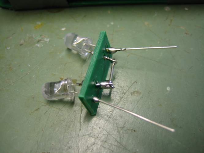
After that I decided to rearange the microswitches. They are now placed with more space between them. This gave me the possibility to place two LEDs between them and reduced the depth the buttons have to be pushed.
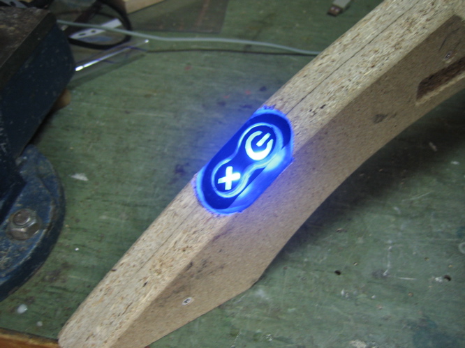
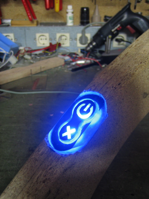
Result with LEDs on:
The whole unit is now conserved in hot-melt adhesive for more easier handling:
With the router I cut out the cabeling ducts and the space for the switch unit:
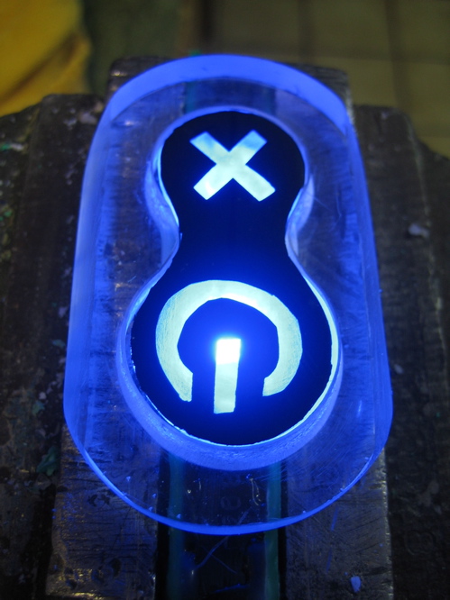
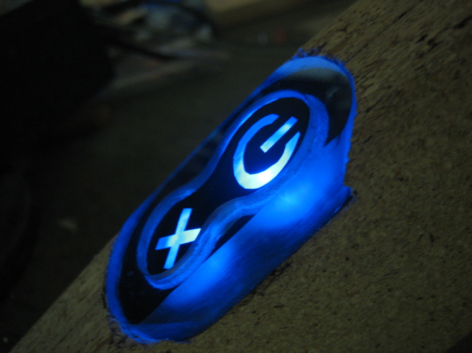
Nice shots with the stuff put together:
The last shot shows the LEDs dimmed, because the cam overexposed the shots.
I still need the power and reset logo in a better quality. My free-hand cuts suck
I also worked on the logo in this foot and cut it out of the wood and made two plexiglas pieces but I keep that for the next update (hopefully tomorrow).
@blueonblack Thanks.
@Helix: Thanks! - Thats exactly what I am trying to do: Thinking outside the (PC-)box.
I collected enough pics for the next big update. So here are the news:
A little work on the right foot, basicly the same as on the left one:
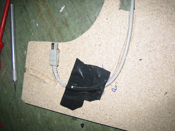
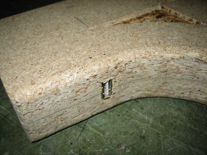
Mounted the USB-connector:
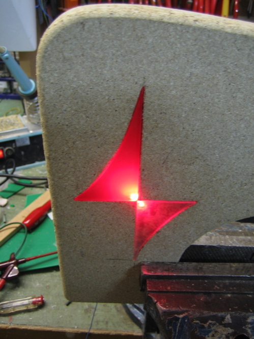
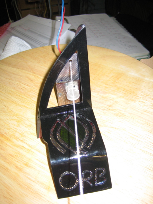
Carved in my logo and cut out the corresponding plexi parts. Also added two LEDs:
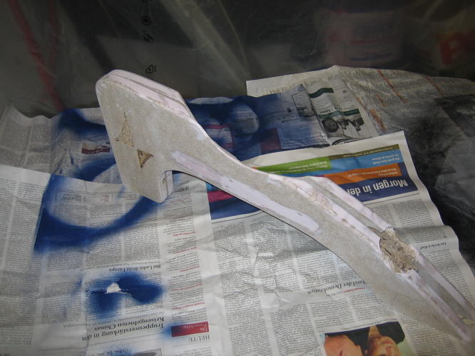
Somehow I lost about 5 pictures from my work on the baseplate Well, you can see it here.
I had to fill a gap in front of the mainboard and also the paint got some scratches. So I sanded it completely and painted it again. The result with a clear coat:
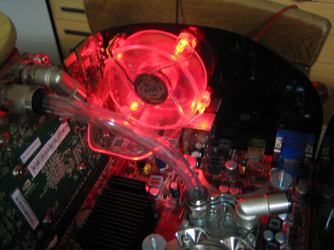
Finally completed the fan for the motherboard (the beginning can be seen here).
These are the mounting brackets (I arranged them for the pic like Tribaloverkill does ) These are glued to the plexi pipe and bolted to the backplate.
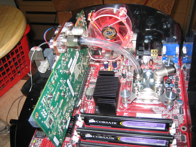
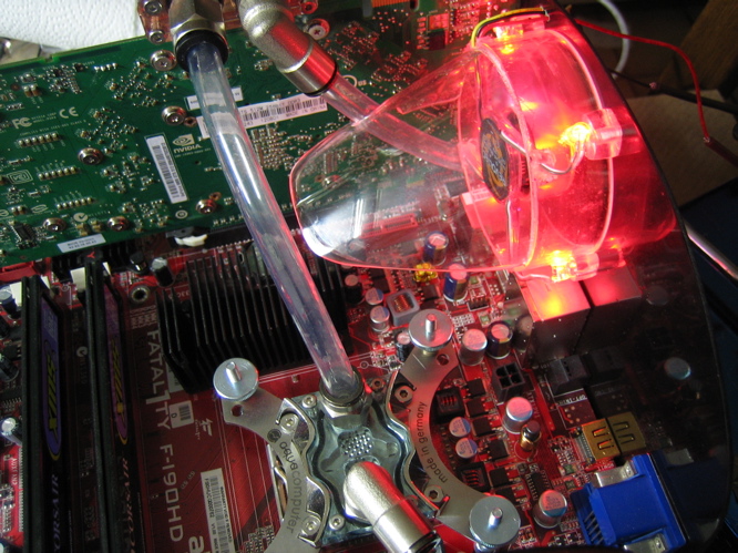
Result looks like this:
Quite happy with that glow
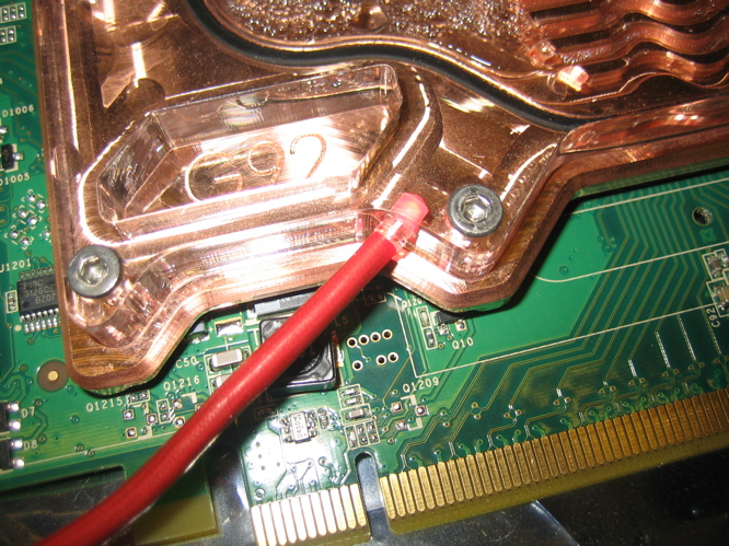
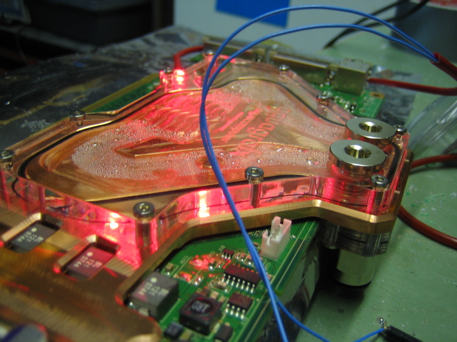
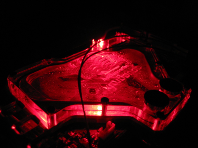
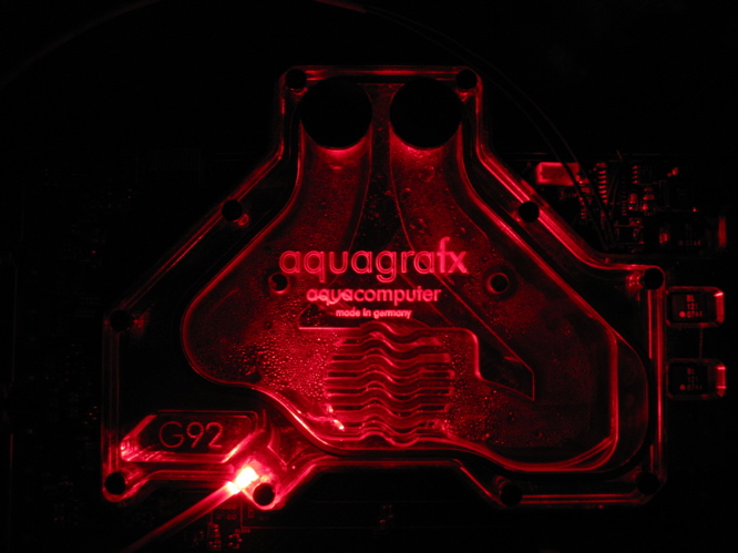
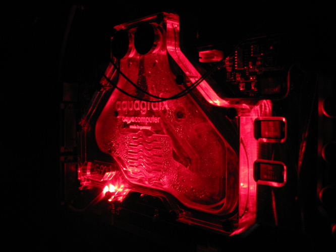
When I saw that, I simply had to improve the watercooling block of the GeForce. One little hole and a red LED and it looked so much better:
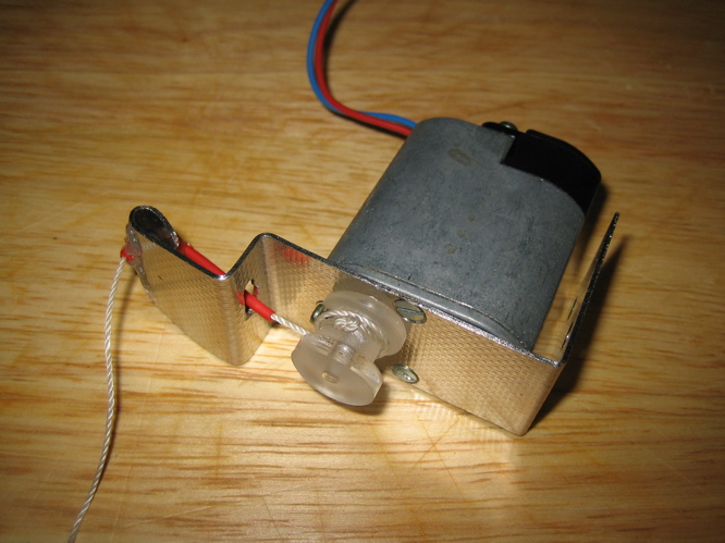
Another redo of a part is the mounting for the motor moving the visor. I enlarged it so now the deflection pulley is no longer part of the hinge cover but a part of the mounting. That way is much more stable:
Last thing: The hinge cover itself with some new holes for the USB cables. Fortunately the USB connectors are only some milimeters away from the hinge cover, so you barely see the cables
Wow, I think this update sets the new maximum regarding the pictures. Hope you like it!


One more +Rep for you Brinkz0r.
Just kidding!


 Another version of the backplate. Had to make a new one after I noticed I drilled two holes much too big
  But this time it's perfect. I also cut the holes for the fan:
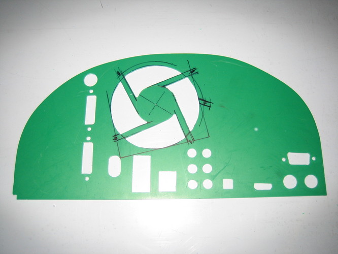
 It's the packaging of an old Motorola mobile phone. The cage is made of aluminium and it already has a nice window. That would be perfect for an external DVD where you could watch the disk spinning...
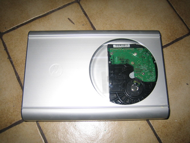


 Thank you so much! *showingthevidtoeverybody*
 Thanx a lot TBCS! This deserves an update: