Wow, I totally thought about doing this mod a year or so ago. +rep for actually doing it
As for the lights on top I'd just have multiple lights for HD activity and such


Wow, I totally thought about doing this mod a year or so ago. +rep for actually doing it
As for the lights on top I'd just have multiple lights for HD activity and such
WH1T3 0U7
*******************************
Modified Thermaltake View 37
Intel 9900K, MSI Z390A, 128GB (32GB x4) GSkill Royal 3200MHz, RTX 3080 Vision, EVGA Nu Audio, 1TB Silicon Power SSD, EVGA 1300G2, ID cooling 360mm AiO, LG 3440 x 1440


Thanks TGS - I was pretty much thinking along the same lines. Basically, my current plan is as follows:
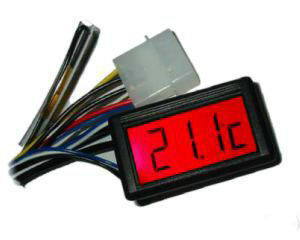
And I think I'll just buy a pair of these:
Put one in as-is, and tear the other one apart to get the surround so it matches, then put a piece of frosted perspex in it with an LED or two for the HDD activity.
As for a power light - I'm planning on illuminating the inside of the case, maybe adding a downlight under it etc so there'll be no doubt if it is on or off...
The two spare buttons, I think I'll just wire in LED's - all of the lights will be on permanently so it won't make a huge visual difference.
Anyone know what the "usual" max rating for the motherboard LED headers is - can I get away with running more than one LED in parallel off of the header or will I blow something up???
Current Projects: Lobo | Unimatrix | High Voltage | Antec 900 Revamp (Phase 2)
Completed Projects: General Lee | Synergy Green | Liquid Yellow
Planned Projects: K-9-PC | Limey
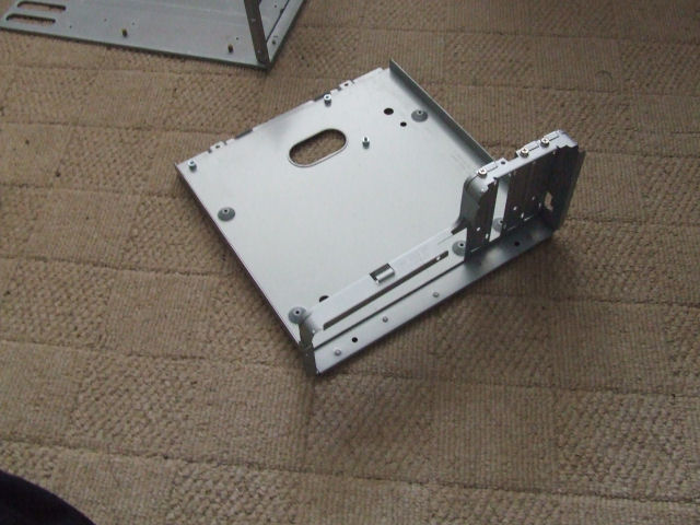
I have a choice of two drive bay setups for this project - well - two I'm considering anyway - one from a shuttle and one from a silverstone media center case
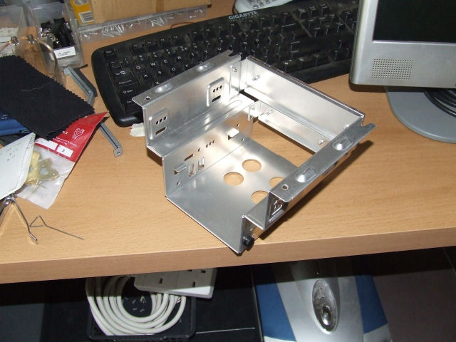
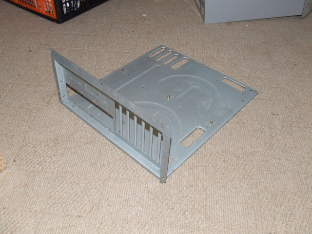
Shuttle:
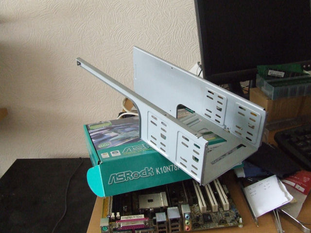
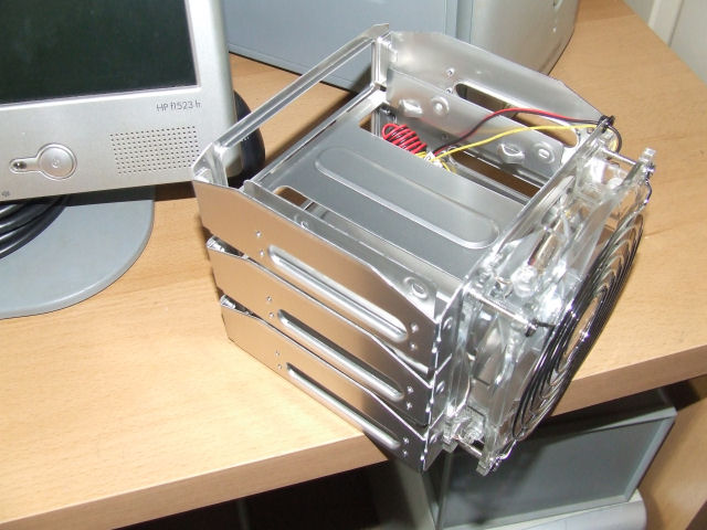
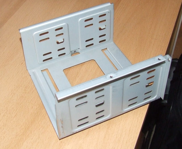
Silverstone:
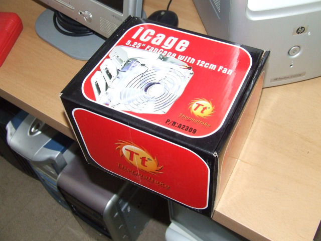
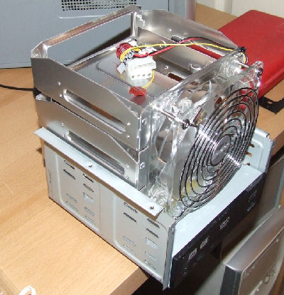
If i opt for the shuttle one, I'll have less dremel work to do, no dedicated cooling, one optical and 2 hard disk slots. If I go with the silverstone one, there's a fair bit of cutting to do (not really a problem) and then room for one optical and three hard disks because the iCage (shown below) will quite happily sit when just attached to one drive bay
Like so:
I'm personally leaning towards the silverstone solution for the extra cooling, lighting, extra hard disk bay and the relatively long mounting slots will allow me to fine adjust the drives to sit where I want them without having to be UBER precise in my construction. Having said that - any thoughts? I may be overlooking something you guys can spot....
Second dilemma - I now have TWO removable motherboard trays:
Obviously one is a lot smaller - both should fit without any problems - the MATX one will give me more room around it to play (my son's PC is currently running on a MATX mobo) but the full ATX one will allow better potential for the future (I hope) - again - opinions welcome but I am leaning towards the full ATX as that IS the one I originally drew up my plans around...
Current Projects: Lobo | Unimatrix | High Voltage | Antec 900 Revamp (Phase 2)
Completed Projects: General Lee | Synergy Green | Liquid Yellow
Planned Projects: K-9-PC | Limey
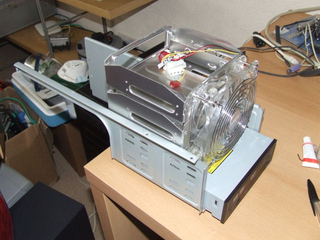
Ok so I went with the silverstone drive option and have cut it down to just the part that I need.
And a quick test fit of the drive & icage to make sure I'll be able to get the drives nice and smooth against the front of the case behind the flap...
Going to paint it all black anyway, just to keep with the dark innards of the case I want - should make the lighting I put in a little more effective etc.
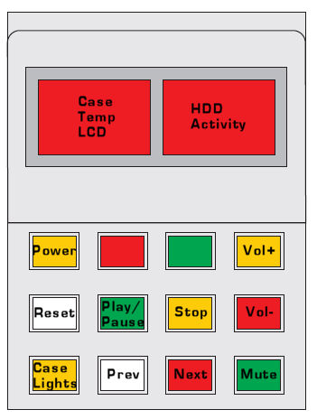
And now I NEED help please fellow geek type people. Let me explain....
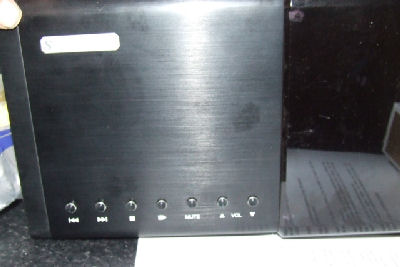
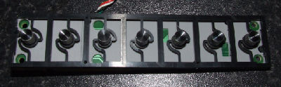
I took the buttons out of the silverstone media centre case...
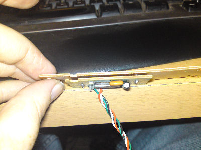
And then took them apart to check on how to rewire them into the control panel on the top of the case...
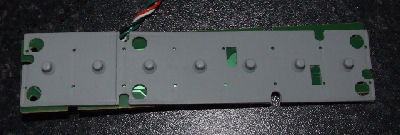
and on the back of the board is this...
it's actually two boards, back to back, with 8 pins going from one to the other....
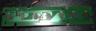
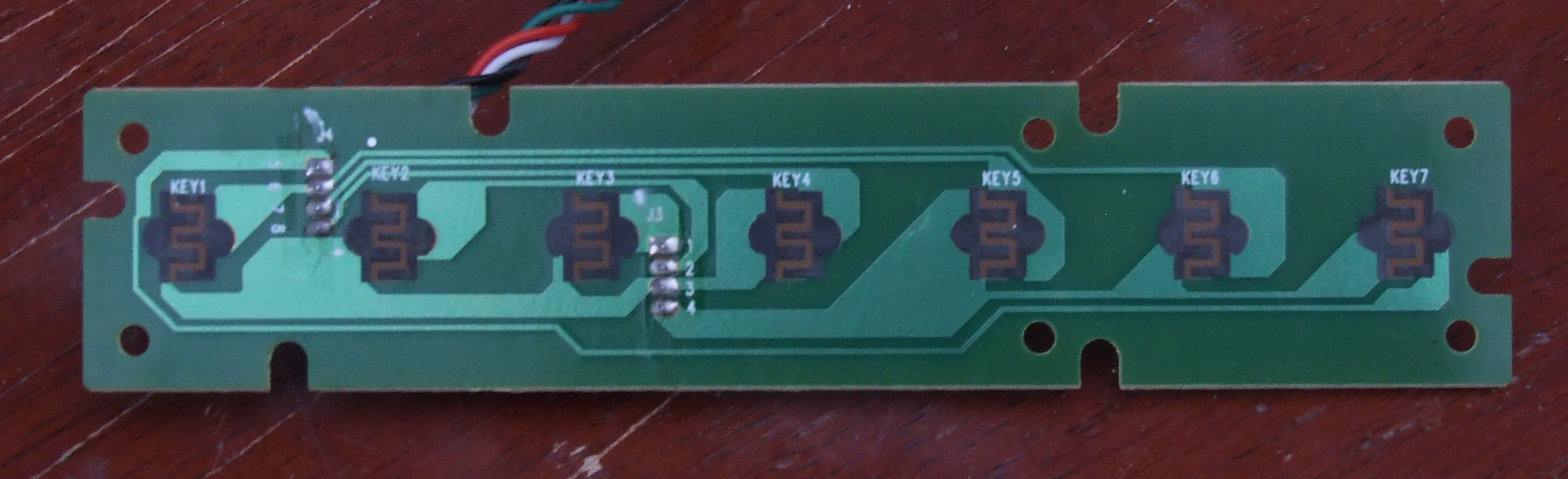
But there are no physical buttons to rewire - it appears to be a touch-sensitive panel. I thought at first, with 7 touch-pads, and 8 connectors going between the touch-board and the control board, that there's be a common ground, and 7 "live" but when I've looked at the circuits, it doesn't appear to be the case - I have done my best to copy the circuit layout here for clarity....
The 1-8 are the pins going to between the controller and touch boards, and K1 to K7 are the 7 touch sensitive sensors - and they appear to be wired as follows...
K1 - Pins 3/6
K2 - Pins 2/3
K3 - Pins 1/3
K4 - Pins 3/8
K5 - Pins 4/7
K6 - Pins 4/6
K7 - Pins 4/5
So, two things - one does this actually make sense to anyone because I'm not an electronics guru. The second is a little more cheeky....
My soldering is barely competent, at best - is there anyone out there willing to lend a hand with this - I THINK what needs to be done is the solder removed from the 8 pins on the touch-board side and that whole board removed - then individual wires connected to each of the 8 pins, or alternatively, a new board fabricated to replace the touch-board and give more accessible contact points for wiring in cables to then connect to the momentary push-to-make switches I'm using for the control panel on the back...
I'm obviously more than willing to cover any costs and I don't expect anything for nothing, but if there's someone who can help me get past this hurdle, I'd really really appreciate it - I don't want to end up with 10 buttons on the back that effectively are just lights.
I'm in the UK but really don't care where you are - I'll ship to whereever I need to - can anyone help?
Current Projects: Lobo | Unimatrix | High Voltage | Antec 900 Revamp (Phase 2)
Completed Projects: General Lee | Synergy Green | Liquid Yellow
Planned Projects: K-9-PC | Limey
Just in case I screwed up when I made the circuit diagram, here's a hi-res image of the board ....
It'll probably end up resized - here's a link to the original...
http://www.slaveofconvention.com/ima...cuit-hires.jpg
Current Projects: Lobo | Unimatrix | High Voltage | Antec 900 Revamp (Phase 2)
Completed Projects: General Lee | Synergy Green | Liquid Yellow
Planned Projects: K-9-PC | Limey

I think the designs are fantastic. Can't wait to see the robodog.
Well I can't take credit for the design - just the implementation - thanks though!
Current Projects: Lobo | Unimatrix | High Voltage | Antec 900 Revamp (Phase 2)
Completed Projects: General Lee | Synergy Green | Liquid Yellow
Planned Projects: K-9-PC | Limey

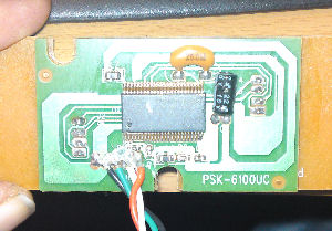
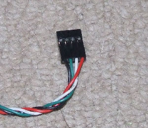
What's on the other end of the green, black, orange and white wires? USB connector? I can likely help if no one on your side of the Atlantic volunteers but testing could be a problem if that's not a usb connector. PM me if you want to give it a go.

Sorry I can't help out. I'm sure someone will. G/L
Yes, it's a standard 4 pin female connector to go onto an internal USB headerOriginally Posted by Mach

Current Projects: Lobo | Unimatrix | High Voltage | Antec 900 Revamp (Phase 2)
Completed Projects: General Lee | Synergy Green | Liquid Yellow
Planned Projects: K-9-PC | Limey
 Posting Permissions

 Reply With Quote