-
 Re: Project: Power House
Update time
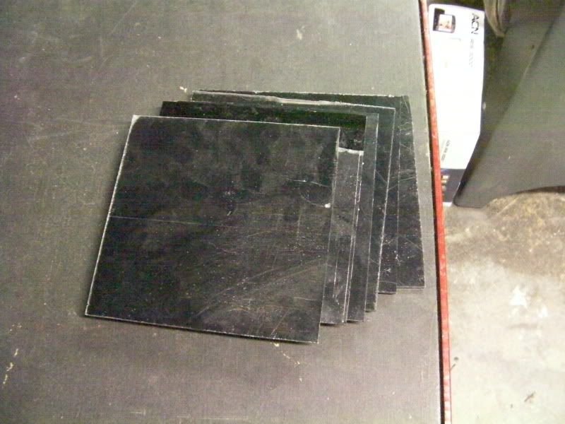
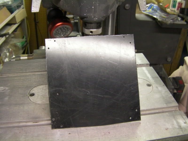
I got the 6 wall pieces cut out. Each measures roughly 7 5/8" square.
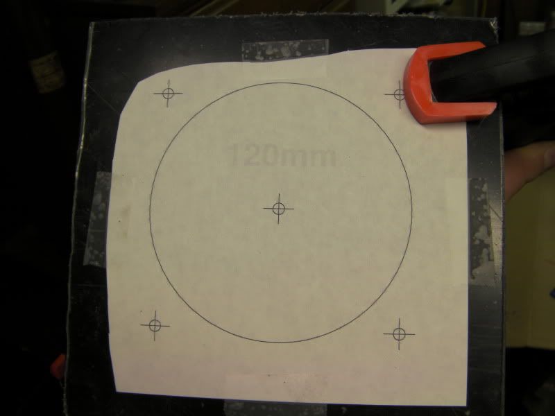
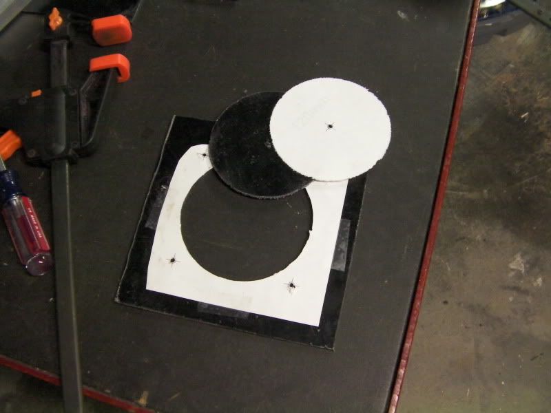
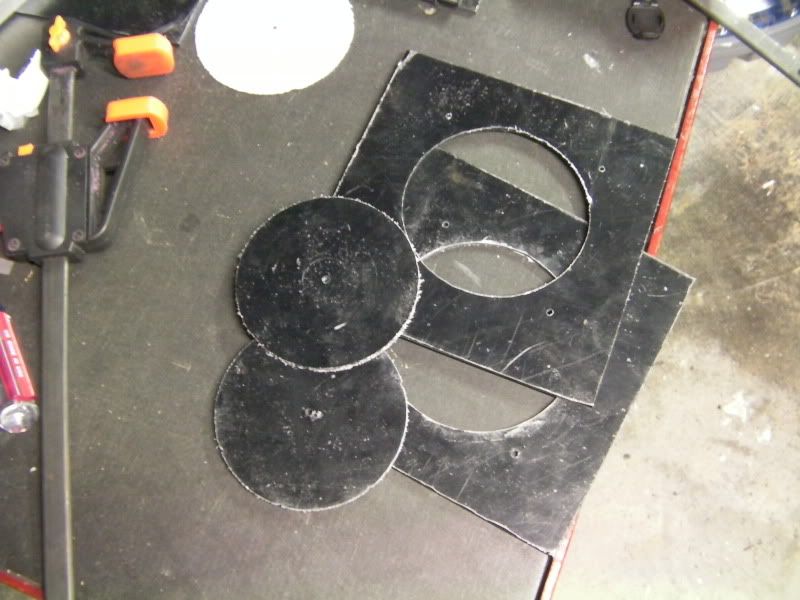
Then I used a 120mm fan template from MNPC Tech and cut fan holes in 2 of the panels with my Dremel and the SWEET circle cutter attachment 
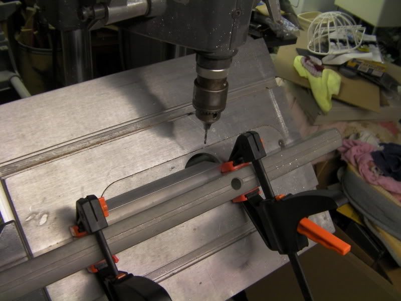
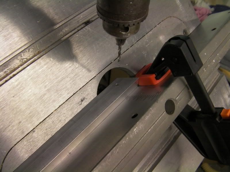
Next I used the drill press, and tilted the table at a 45º angle so I could drill straight through the angle beam where I marked. I marked 1" in from the ends and 1/2" from the bend. I used the clamps so I only had to measure one piece, and just butt up each subsequent piece to the clamp and it'd be dead on.
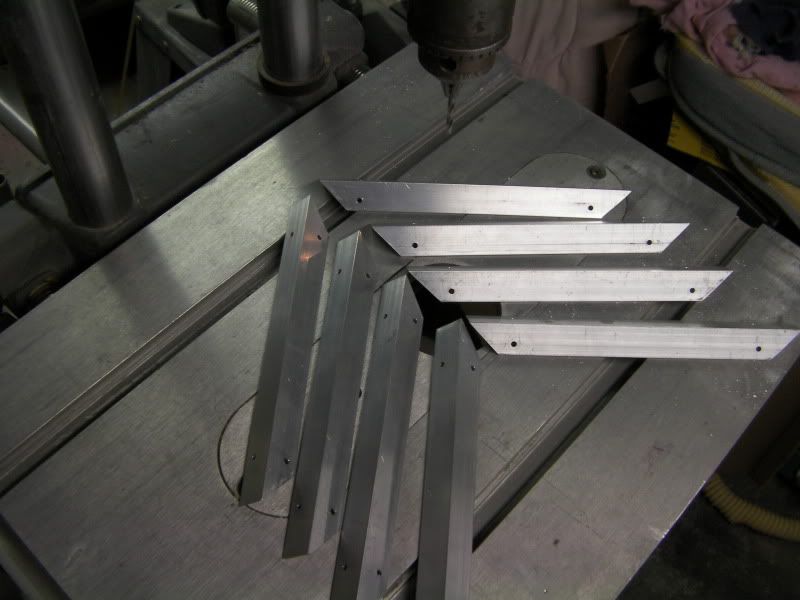
And all the pieces drilled
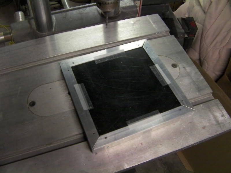
Next I taped the 4 frame parts together, then I taped one of the panels (the bottom in this case) to the frame for drilling.
The panel drilled
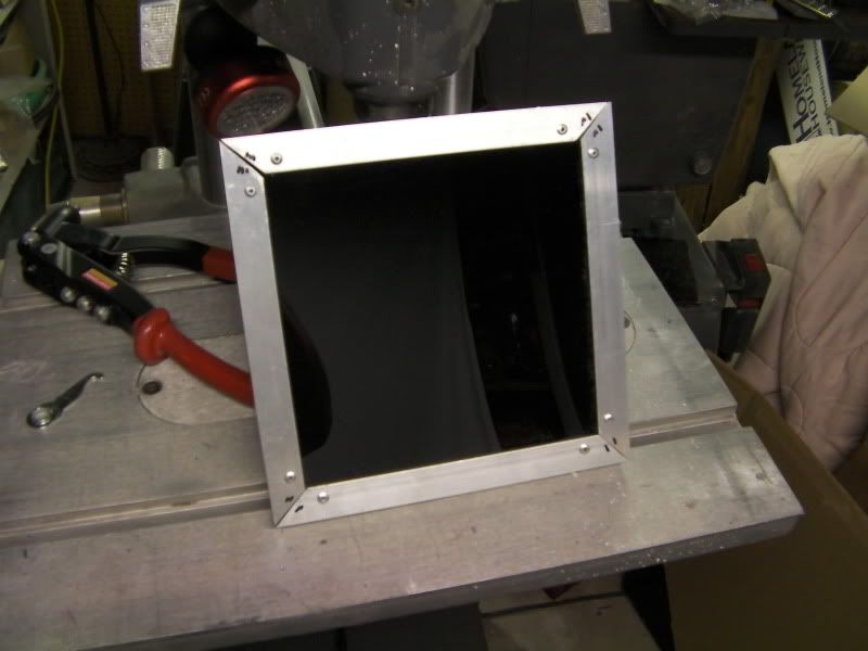
And riveted. This completes the bottom frame section. These corners don't line up 100%, but it's the bottom so I'm not worried. I will file the top ones so they all fit nicely together.
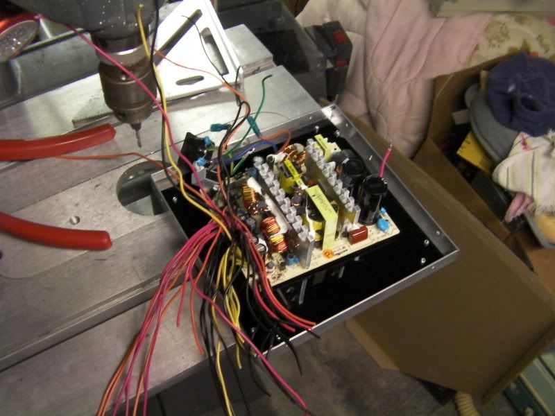
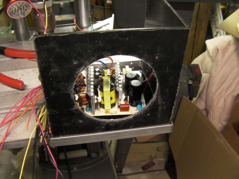
Here's the PSU internals laid on the bottom. This will actually be mounted to the rear part, but this gives an idea of size.
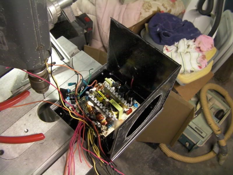
And with 2 panels sitting in place.
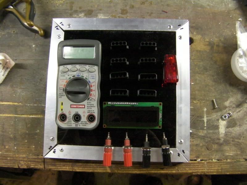
And I laid out the components to get an idea of fit and size. I plan to put a 2p connector under the main power switch. This will be hooked to the 3v supply to test LEDs. I didn't put a spot for a power LED, as the switch I got has an LED in the tip of it.
That's all for tonight!
-
Re: Project: Power House
I found that lining up the corners is SUPER hard in making a frame like this. The metal on my xbox mod doesn't line up either, even with lots of careful filing.  Just like you though, mine is the bottom so I can't be too bothered to fix it. lol

Originally Posted by
Omega
ber is id elicous
Centurion 5 Mod <<--- ON HOLD FOR THE WINTER
-
Re: Project: Power House
yea, I plan to do whatever necessary to make the tops fit, as they will be seen and I want them to be perfect (or close to it)
-
Re: Project: Power House
Man, I wish I thought of this sooner.
Figuring out how to tie a wattmeter into the line.
-
Re: Project: Power House
I'm actually working on that at the moment Either a watt-meter or an ammeter in addition to the voltage display. I plan to have a push button to cycle through the different modes.
-
Meow


Re: Project: Power House
-
Re: Project: Power House
Originally Posted by
Drum Thumper

you tease!
-
Re: Project: Power House
thanks
-
Re: Project: Power House
What about adding an adjustable output from one of the 12v lines? I have a schematic that uses just a few components and will allow 1.3v-12v
Nice job BTW
-
Re: Project: Power House
I love the idea but I've got one concern. The measuring circuit for the 12v line uses two resistors as a voltage divider, if the voltage gets low enough will that cause issues with the Arduino reading? But then again if I need to go down to 5v I already have a 5v line. Shoot over your shcematic!
I'm working on getting an amperage measurement worked into my LCD display as well. Once I get that sorted maybe I'll work your regulator circuit into it and have a single PCB made up
 Posting Permissions
- You may not post new threads
- You may not post replies
- You may not post attachments
- You may not edit your posts
-
Forum Rules


 Reply With Quote


