Page 2 of 5 FirstFirst 12345 LastLast
Results 11 to 20 of 47

Thread: Tempest SXR

  1. #11
    Fox Furry crenn's Avatar
    Join Date
    Apr 2005
    Location
    In the shadows behind you
    Posts
    4,067

    Default Re: Project: Tempest SXR

    Quote Originally Posted by SXRguyinMA View Post
    I went to upload that last one, and it popped up with "error: expected unqualified-id before numeric constant" on the "const unsigned char CONTROL = 7" line

    :EDIT: I deleted that line and it seems to work really well. it's just a TOUCH jittery when it moves, but that's fine. The issue I had was it jittering in one place lol

    hopefully I'll have my parts tomorrow, and I can get this thing built so I can hook it all up and test it. The jittering may go away when there's a slight load on the servo. If I lightly push it with my finger and put a load on it it seems to stop jittering
    I see why it had the error, I forgot to remove
    Code:
    #define CONTROL 7
    so it was seeing when it compiled
    Code:
    const unsigned char 7 = 7;
    which isn't what I wanted, the code will be update in 2 ticks to reflect that. Increase the number of samples to 20 (change MAX_VAL) and see if that helps.
    Antec Sonata II | Pioneer DVR-212
    Good news! You can follow my website or follow me on twitter!

  2. #12
    Resident 100HP water-cannon operator SXRguyinMA's Avatar
    Join Date
    Jun 2008
    Location
    MA
    Posts
    5,865

    Default Re: Project: Tempest SXR

    here ya go click for bigger pics

    He forgot to make 3 pieces though, which he said he'll do in the morning. So once again, a HUGE thanks to Tom over @ HydroCutter for doing this for me!!!

    Everything fits a little tight, but that's perfect. The edges are almost perfect and will only require a little bit of sanding, but that will smooth them and make everything fit perfectly. Then once it's all glued together I'll bondo it up and sand it so it looks nice. I'll get some close-up pics of the edges tomorrow.

    the holes in the mounting tabs are 1/8" and the space between the hole and the edge is 1/16". Not bad for 60,000 psi of water traveling over 1,700mph!


    now I've got plenty of clear 1/8" acrylic rod left from rockin case, so I will use that for the hinges. hopefully this week I can get some work done on this and more work done on the LEDs as well

  3. #13
    Resident 100HP water-cannon operator SXRguyinMA's Avatar
    Join Date
    Jun 2008
    Location
    MA
    Posts
    5,865

    Default Re: Project: Tempest SXR

    here's a few close-ups of the edges. they're pretty damn smooth for such a soft material. there's a slight bit of browning on some of the edges, but that was to be expected. it's not deformed at all and will be easily hidden with bondo and paint or sanded away altogether.

    the pics came out ok, I need to get or make a nice photo box setup to get better lighting though


  4. #14
    Resident 100HP water-cannon operator SXRguyinMA's Avatar
    Join Date
    Jun 2008
    Location
    MA
    Posts
    5,865

    Default Re: Project: Tempest SXR

    Update time!!!

    After about an hour of sanding on the fins i got them all to fit in perfectly


    I then took all my hinge pieces and filed out the holes until the acrylic rod slid in easily, then stacked them all up to sand down the mating surfaces


    after they were all sanded I laid them out in their places


    I ran a piece of rod through 4 of the mounts so it would keep them properly aligned. I measured 1" from each fin edge (the middle of each fin) and scribed a line to mark where each piece was to line up.


    Then I used some ultra thick CA glue with a 10-25 sec. set time and glued the parts in their places


    3 sets done


    All 5 sets done. This took quite a while to get right, as I needed to nudge each part gently to get it to properly line up, then glue with one hand while holding everything steady with the other. I set the actuating rod in place to help line up the 5 actuating arms, and put 15 temporary pins in to hold everything together.


    Opened


    I used painter's tape to hold the 3 edges on so I could sit the unit on the case over the fans and check clearances.

    Louvers closed


    And opened


    Now I've got a bunch of sanding and filing to do on the edges of the louvers so they all open and close smoothly. Currently in the closed position they catch on each other when trying to open, so I'll probably end up beveling the edges to loosen it all up. If it doesn't work well enough I'll probably have another set of mounts cut out and put the new mounts farther to the rear of the louvers to change the pivot point. We'll see what happens though. Hopefully within the next few days I can get them all sanded and check clearances.

    I'm also going to cut some small ledges to glue to the bottom backside of the louvers, so when they're closed they'll sit perfectly flush

  5. #15
    Resident 100HP water-cannon operator SXRguyinMA's Avatar
    Join Date
    Jun 2008
    Location
    MA
    Posts
    5,865

    Default Re: Project: Tempest SXR

    Quote Originally Posted by x88x View Post
    Niiiice. That's gonna look awesome once it's hooked up.
    Thanks I just need to figure out where I'm going to mount the servo then make some mounts for it and it'll be pretty much ready to go! There will just be a nice bondo coat to fill in the gaps and then some black spray paint to cover it all up. I'm just not sure @ this point if I want to do gloss black or matte black...maybe I'll paint one louver in each and see how they look with the rest of the case.

    Quote Originally Posted by Oneslowz28 View Post
    Looking awesome! I showed this to one of my contacts and lets just say they like it!
    Thanks CJ!

    Quote Originally Posted by StormRider View Post
    I'm gonna have to learn how to make something like that. I already have a plan for it too
    sweet work on the case so far!
    It's easy really. I designed it all in sketchup then added all the measurements and printed out the drawings and handed them to Tom @ HydroCutter and said make me this

    Ok well it was a little more involved and time consuming than that lol, but it did go together quicker tonight than I thought it was going to, so I'm pumped

  6. #16
    Resident 100HP water-cannon operator SXRguyinMA's Avatar
    Join Date
    Jun 2008
    Location
    MA
    Posts
    5,865

    Default Re: Project: Tempest SXR

    Quote Originally Posted by msmrx57 View Post
    Farging AWESOME!!!!!!! That is sooooooo damn cool. +rep for sure
    Thanks!!!

    Quote Originally Posted by crenn View Post
    I want to see this in action! I'm also curious the radius of the arm (from pivot to connector) for each panel and the radius of the servo.... just curious!

    Also you're welcome for the code, didn't take too long to write up and hopefully will work exactly how you want it to!
    Not sure exactly what you want for measurements. I think this is what you were asking for. It's all the dimensions for the actuator arms. I can't seem to find out how to make sketchup show angles like the rest of the measurements though, but the angle is 30º. The smaller pieces are the same but without the extra arm coming off. Hope this helps


    :EDIT: upon further research it would appear that SketchUp does NOT DO ANGLE MEASUREMENTS like it does the other length measurements. Seems to be a rather important thing they left out. However you can jsut use th eprotractor to find the angle and make some text pointing to it with the angle I suppose

    oh and it's 1/2" center to center on the holes

  7. #17
    Resident 100HP water-cannon operator SXRguyinMA's Avatar
    Join Date
    Jun 2008
    Location
    MA
    Posts
    5,865

    Default Re: Project: Tempest SXR

    Smallish update!

    I did all the needed sanding to get the fins to not catch on each other anymore, they all open and close smoothly now. I also added small tabs to the bottom of each one so they will only close until they're flush and won't more any farther. This will also alleviate any play in the linkage that might keep one fin open a crack while the others are closed.

    I also finished gluing all the mounts. Now I'll just have to do some finish sanding on the glue and finish sanding with higher grits on the fins to take out the scratches before everything gets painted.

    Hopefully this weekend I'll get to finish all the mounts permanently with the acrylic pins glued into place, and get the servo mounts made and the servo mounted. That's all for now!

  8. #18
    Resident 100HP water-cannon operator SXRguyinMA's Avatar
    Join Date
    Jun 2008
    Location
    MA
    Posts
    5,865

    Default Re: Project: Tempest SXR

    Update time!

    The original actuator arm I had made broke because I made the walls around the holes too thin. So I cut a piece and made myself a new one


    Then the 3rd side was glued on


    The 1/8" acrylic rod pieces were glued into their respective holes in the actuator arm


    I drilled a small hole to thread in this ball stud


    Now I had to swap out my micro servo for this standard one because the linkage I wanted to use was too big for the small arm on the micro servo


    I made some servo mounts


    And all glued up


    That's it for now while the glue sets up. Tomorrow or Thursday I should be able to hook this puppy up and test it! The linkage I used was from the forward/reverse servo from my old Traxxas T-Maxx. It's got 2 springs that should help keep the louvers shut as I can have the servo go a little past the point where they close and it'll hold them shut nicely.

    Once it's all tested, all that's left is to finish gluing up the rest of it, make some mounts to mount it to the case, then bondo it up, sand it, and paint it!

  9. #19
    Resident 100HP water-cannon operator SXRguyinMA's Avatar
    Join Date
    Jun 2008
    Location
    MA
    Posts
    5,865

    Default Re: Project: Tempest SXR

    Quote Originally Posted by x88x View Post
    Very nice. Looks like there's plenty of space for the larger servo too.
    Thanks! Yes there should be plenty of space for it. The next step is to temporarily mount the 2 top fans and place this on and check all clearances and see how far open the louvers can go before they hit the fans, if they hit at all.

    Quote Originally Posted by crenn View Post
    How come you moved to a ball linkage if you mind me asking? I don't think that was in the original design.
    TBH I never really had a set design in the beginning as far as hooking the servo the the actuator arm. I was planning on building the assembly, then mounting the servo wherever possible and using whatever linkage needed to make it work. I've got a ton of old R/C car stuff laying around (hence this servo and linkage) that made that part easy. I ended up needing the ball socket part because it was going to be nearly impossible to get the servo mounted exactly how it needed to be to hook it directly to the actuating arm. This way allows a little more flexibility in servo location as well as some give in the whole setup, which will be needed once I get the system up and running to properly calibrate the servo to the temp readings.

    The linkage was from the forward/reverse selector on the transmission and that particular servo was a hi-torque one that was used in the steering. I had to swap it into a new case and solder on new connector and wiring (R/C nitromethane fuel doesn't do plastic any good)

    Quote Originally Posted by OvRiDe View Post
    Top notch my friend. Looking great! I can't wait to see it in action.
    Thanks! Hopefully just another day or two when I've got a free sec to plug it in!

    Quote Originally Posted by Oneslowz28 View Post
    Looking awesome! This is going to be one of the coolest PC + Arduino mods to date!
    Thanks CJ!!

  10. #20
    Resident 100HP water-cannon operator SXRguyinMA's Avatar
    Join Date
    Jun 2008
    Location
    MA
    Posts
    5,865

    Default Re: Project: Tempest SXR

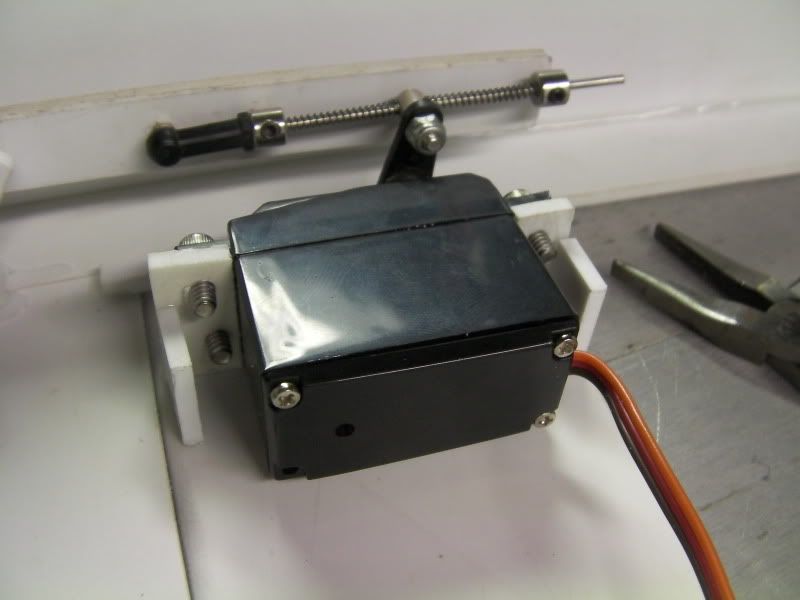
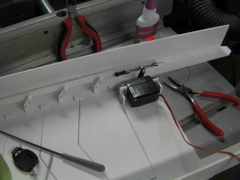
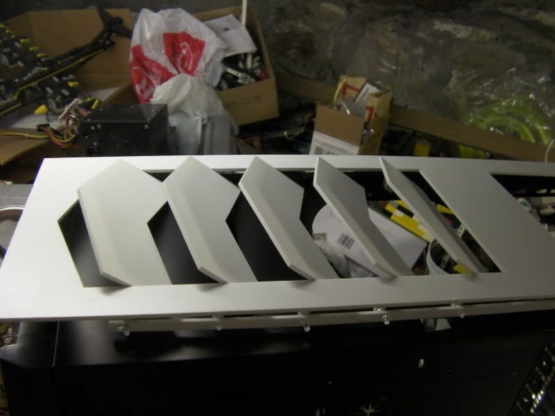
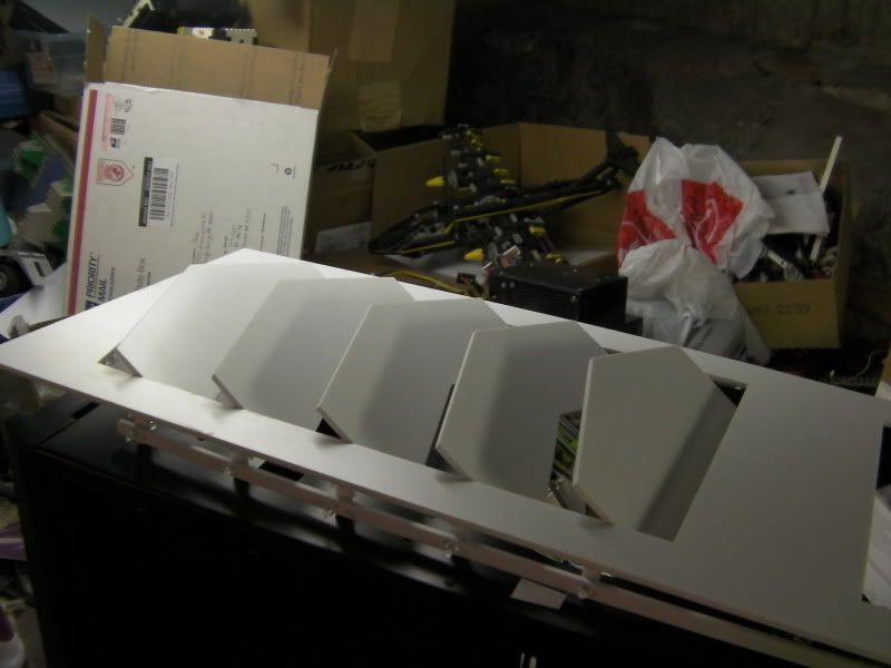
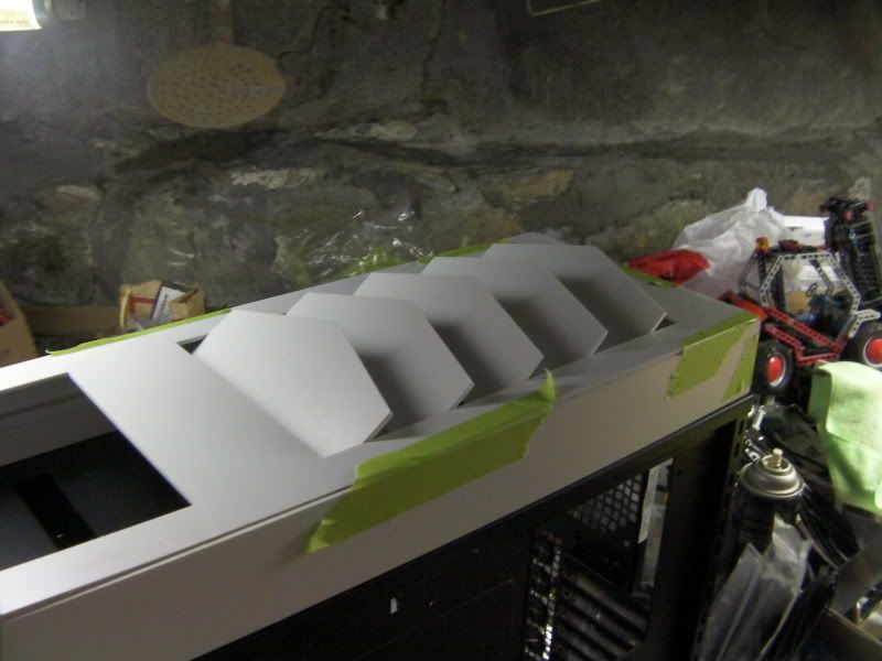
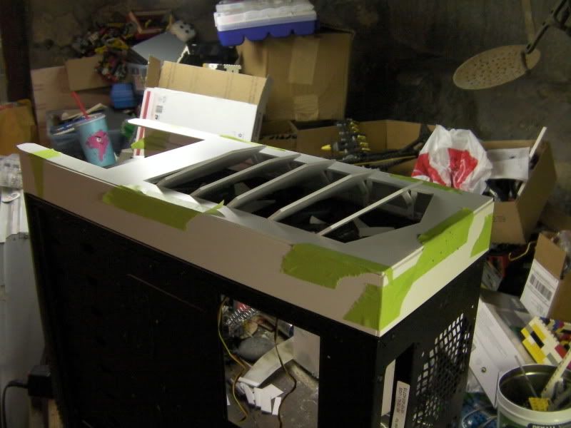
    ok I figured it out. I set the computer off (no voltage to pin 7) setting to 180 instead of 50 (other end of servo). Then I placed the servo arm in it's correct position so the louvers will be closed when the servo is at this position. I then swapped the map=val figures to make the servo spin the other way and set the range of motion for the servo. These readings will need to be adjusted more once I get the system up and running, so I can set the ROM for the actual temps the case sees, not just ambient or in my mouth lol

    Current code:
    Code:
    // Controlling a servo position using a temperature sensor
    // by Michal Rinott 
    // edited 5-12-2010 by Will Lyon to include base setting for servo if voltage not detected on pin 7
    // edited again 7-4-2010 by crenn to simplify the code a little
    // edited yet again 7-5-2010 by crenn to add features
    // edited again 7-21-2010 by Will Lyon - recalibrated servo positions
    
    #include 
    
    Servo myservo;  // create servo object to control a servo
    
    //Constants
    const unsigned char CONTROL = 7;	// digital pin used to detect if the system is on or off
    const unsigned char temps = 0;		// analog pin used to connect the temp sensor
    const unsigned char MAX_VAL = 10;
    
    //Main global varibles
    char trigger = 0;			// varible used to store the control pin value
    unsigned int val;			// variable to read the value from the analog pin
    
    unsigned int updateAvgtemp(){
    	static int history[MAX_VAL]={0};
    	static unsigned char lastHist=0;
    	static unsigned char numHist=0;
    	unsigned int temp=0;
    	unsigned char counter=0;
    	unsigned char arcount=0;
    	history[lastHist] = analogRead(temps);
    	if(numHist=MAX_VAL)
    		lastHist=0;
    	temp=0;
    	counter=0;
    	do{
    		temp+=history[arcount];
    		arcount--;
    		if(arcount>MAX_VAL)
    			arcount=(MAX_VAL-1);
    		counter++;
    	}while(counter < numHist);
    	return (temp/numHist);
    }
    
    void setup()
    {
      pinMode (CONTROL, INPUT);		// sets the control pin to input
      myservo.attach(9);			// attaches the servo on pin 9 to the servo object
      digitalWrite(CONTROL, LOW);		// ensure internal pullup resistor is disabled.
    }
    void loop()
    {
      trigger = digitalRead(CONTROL);	// read input of pin CONTROL  and store it
      if (trigger == HIGH){			// reads if pin CONTROL, if true, do this:
        val = updateAvgtemp();		// read the value of the temp sensor (value with range of 1024)
        val = map(val, 350, 700, 160, 80);	// scale it to use it with the servo (value between 160 and 80)
        myservo.write(val);			// sets the servo position according to the scaled value
      }
      else {
        myservo.write(180);			// sets servo position to 180 if above statment is false
      }
      delay(125);								// wait 25ms for the servo to move to it's new position and also 100ms until it gets the new value
    }
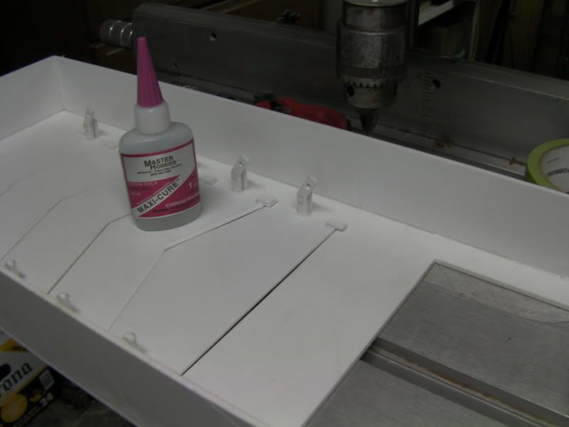
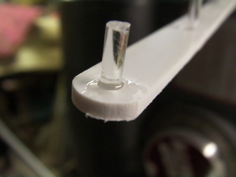
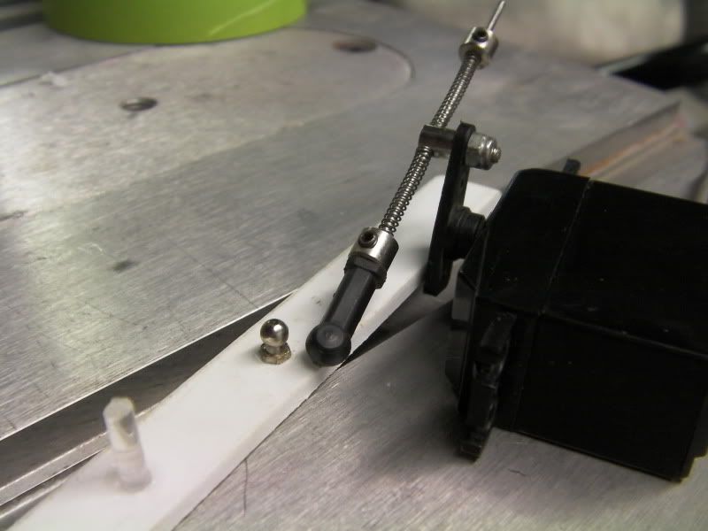
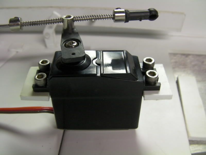
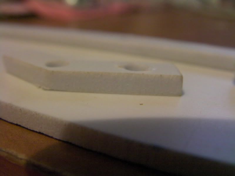
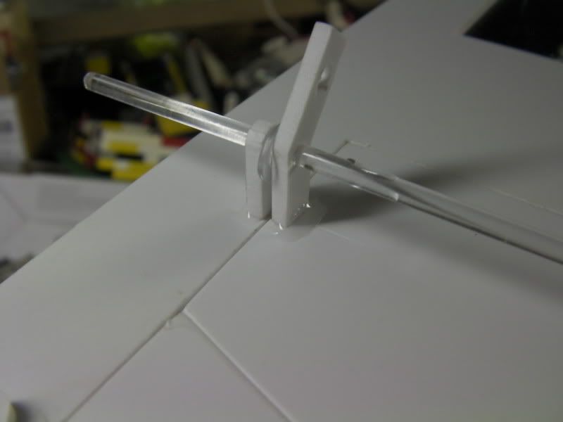
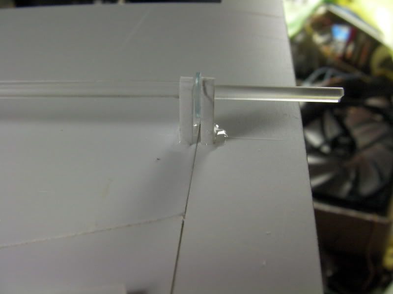
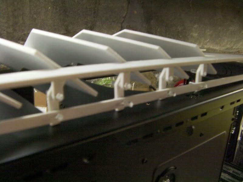
    I was going to get some vid, but during the servo removal process I accidentally broke one of the servo mounts, so I had to re-glue it and it's setting now. Hopefully later tonight or tomorrow I can get it all back together and get a vid of it working!

Posting Permissions

  • You may not post new threads
  • You may not post replies
  • You may not post attachments
  • You may not edit your posts
  •