That sleeving looks smexy.


That sleeving looks smexy.
Centurion 5 Mod <<--- ON HOLD FOR THE WINTEROriginally Posted by Omega

Looks great! I'm uber jelous for the WC RAM XP

man its all coming together!!
think some black velco straps around some of those sleeved cables would look nice? (like on the video card)
Really like the red led's around the mainboard and the UV lights in the blocks and such.
them UV lights actually ought to help kill off microbes in your water system lol!


I actually put some small black zip ties on the VGA cables to clean them up a tad, they look much better now lol. As far as microbes I don't think I'll have that problem with the fluid Kayin is sending me
Arctic Cat * Maximum Security * Cribbage Board * Rockin Case * Armor Redux
Tempest SXR * Power House * Red Comet * ICHIWZ * Acrylic Headphone Hook
Continuing sponsorship support from PCBoard.ca

Love the shot of the PSU with the warranty sticker broken!Do you get a deal with MDPC-X or something? It seems pretty pricey to me to do a whole system in single sleeve with shipping from Europe. Granted it does look better than anything else out there.
Build is coming together nicely, should look awesome when it is finished!
TheMainMan
@TheMainMan - Its only $0.22 per foot + about 9euro for shipping. Whole system sleeved for around $80. Where other sleeving is $0.59 or more per foot making sleeving a whole system well over $150.
Ahh, thanks for the explanation. I hadn't priced out other sources beyond the cheapo kits at a local store (I use them for builds for people who don't care about interior looks). I've been looking at the MDPC-X stuff for a long time but haven't been able to justify that kind of cost while still being a student, so I just get to drool over the pictures of those of you who can
TheMainMan
the MDPC-X stuff is only like $0.20USD/foot lol it's CHEAP
Arctic Cat * Maximum Security * Cribbage Board * Rockin Case * Armor Redux
Tempest SXR * Power House * Red Comet * ICHIWZ * Acrylic Headphone Hook
Continuing sponsorship support from PCBoard.ca
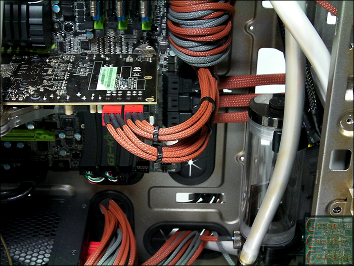
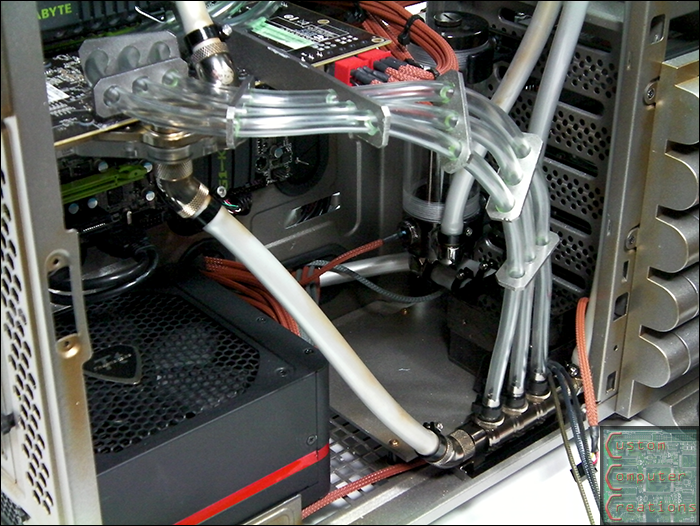
I put some zip ties on the PCI-e cables to clean them up a bit
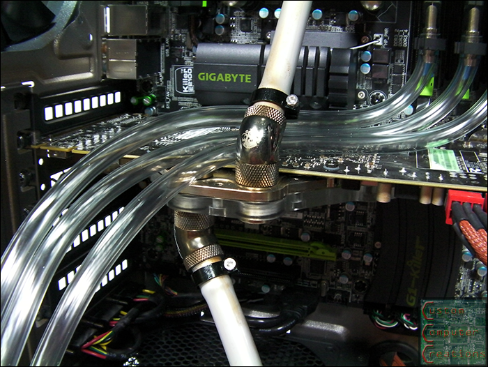
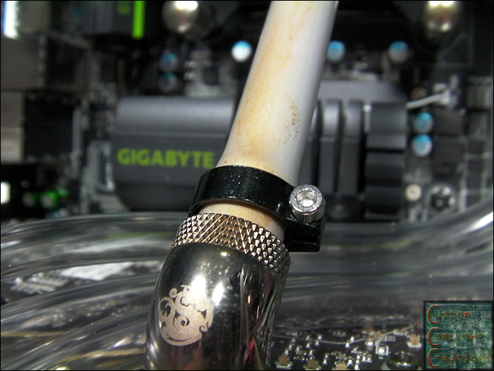
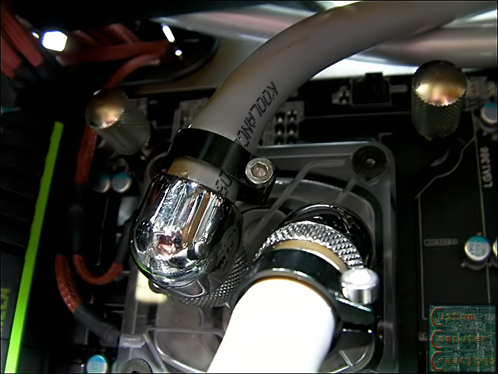
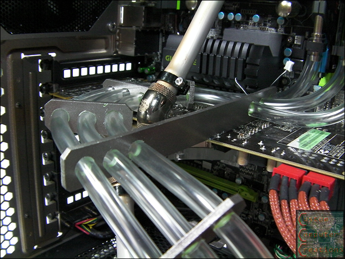
I also picked up these sweet aluminum hose clamps for all the 3/8" tubing. I wanted the same ones for the 1/4" but they were all out, so I got the standard plastic clamps
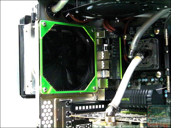
I picked up this Bitspower radgrill for the rear fan
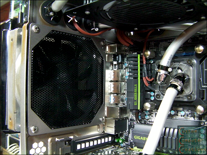
But the green wasn't cutting it so I painted it to match the rest
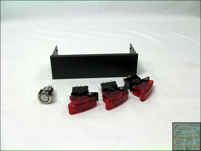
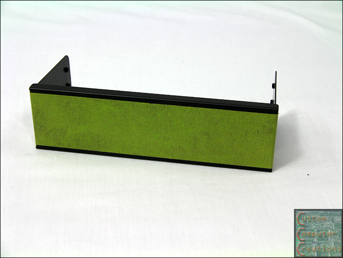
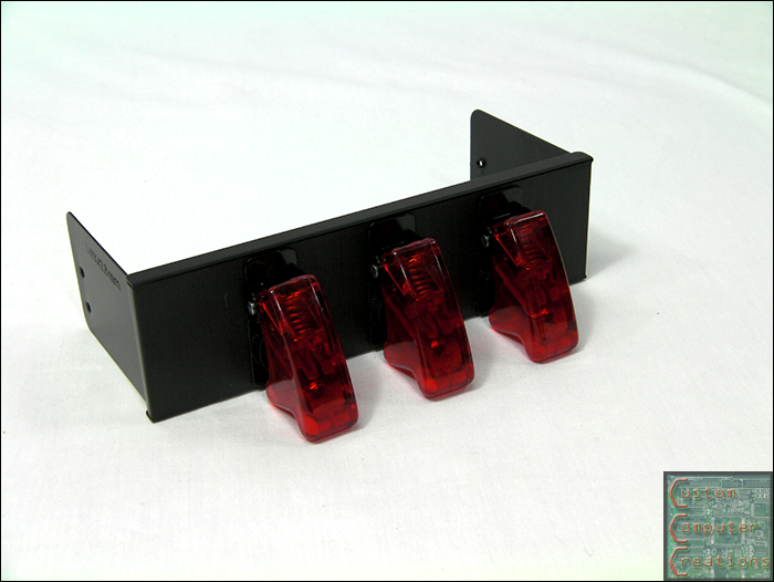
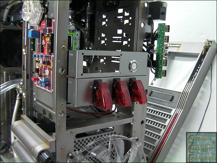
I also got a pair of Lian Li blank 5.25" drive covers and some military switches.
I taped, marked, drilled and mounted everything
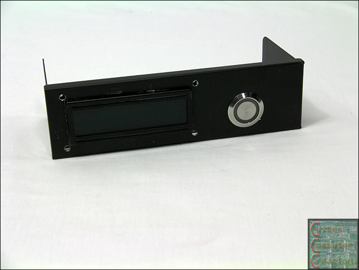
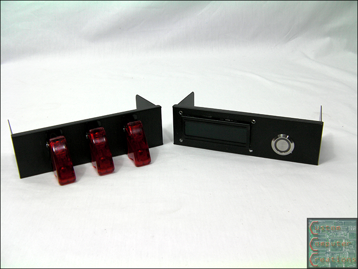
The other holds a 16x2 LCD and a Bulgin button.
I decided to go with a single LCD versus the 2 for simplicity's sake, and the fact that I only really needed one anyways. I also painted both panels to match as well.
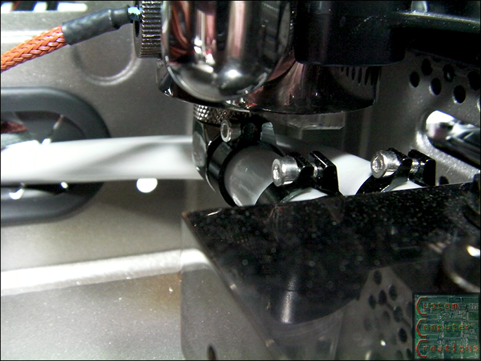
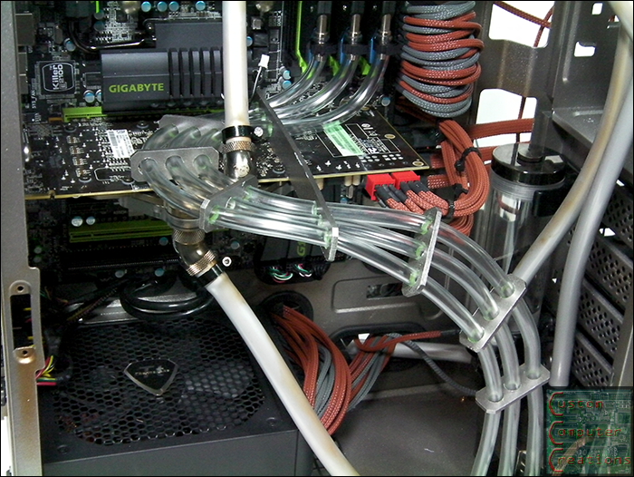
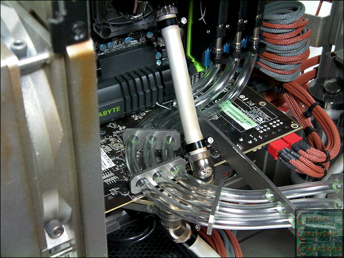
Now I figured I'd do something different with the 1/4" clear tubing for the RAM. I wanted them to do something rather than just be there. So I tried some different routing setups and settled on this one. I cut up some spare plexi I had laying around, sanded, drilled and painted, and here is the end result. This will look sick once the fluid is in there
That's all for now. I've been working a lot with the coding for everything lately. All that's left to do really is finish the switch wiring, finish the airbrushing and integrate the flow meter into the coding one the system is up and running!
Arctic Cat * Maximum Security * Cribbage Board * Rockin Case * Armor Redux
Tempest SXR * Power House * Red Comet * ICHIWZ * Acrylic Headphone Hook
Continuing sponsorship support from PCBoard.ca
Another update
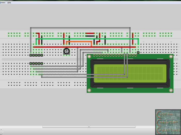
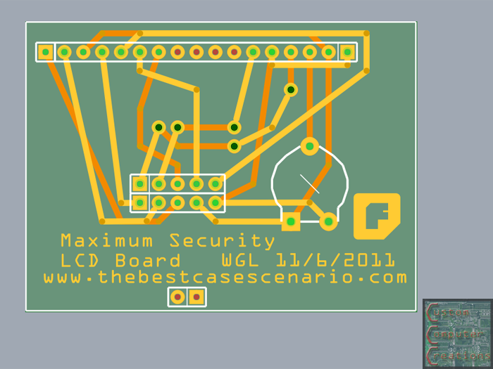
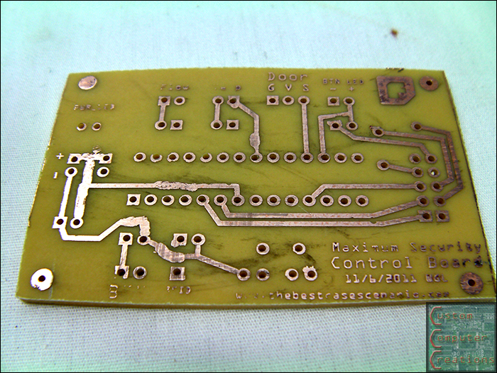
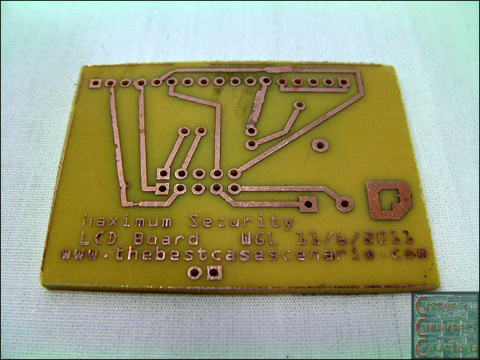
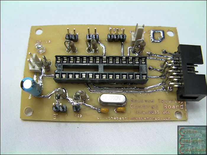
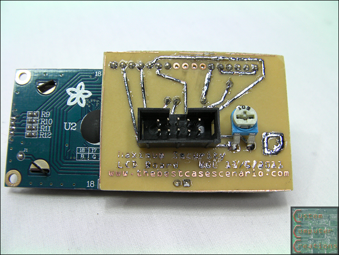
I designed, etched and assembled the 2 circuit boards I'll be needing now that I'm only using 1 LCD. One board will house the ATMega328 and all it's associated components as well as have all the I/O pins for the accessories. The second board will mount to the LCD directly and allow me to use a 2x5 ribbon cable instead of the breadboard-friendly layout as the LCDs come.
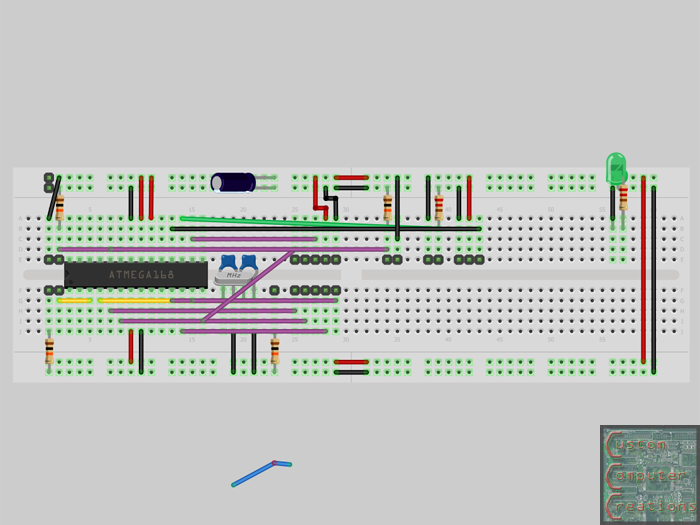
I used Fritzing to create the layouts and the PCBs.
I started off by laying out everything in the breadboard view.
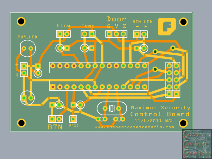
I used that to create the PCB layouts as seen here. From the breadboard point to the ready-to-print PCB point was about 2 hours. This consisted of moving parts around the boards to get the best possible layout.
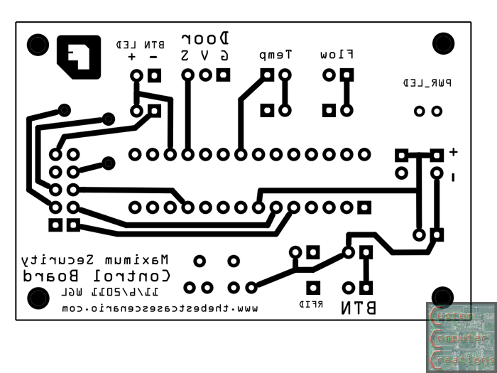
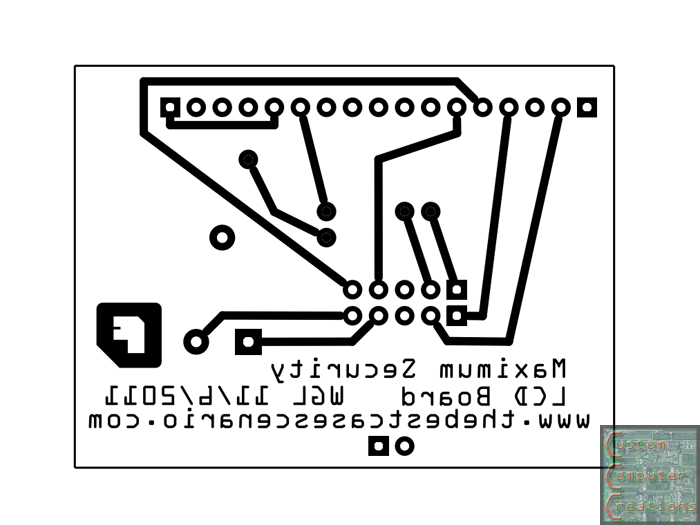
Next I created etchable .pdf's (done with Fritzing) so I can print out the boards. You'll notice one side is mirrored. This is because when you transfer the image it'll come out oriented correctly.
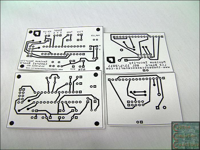
Here the boards are printed out and cut out. They are printed with a laser printer onto inkjet photo paper. The reason for this is that the toner, which is plastic, will not adhere to the inkjet photo paper. This will allow it to be transferred to the copper clad with an iron.
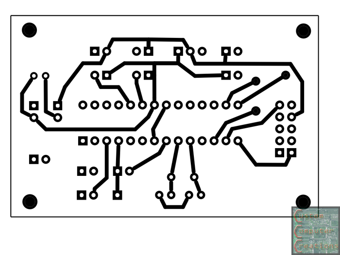
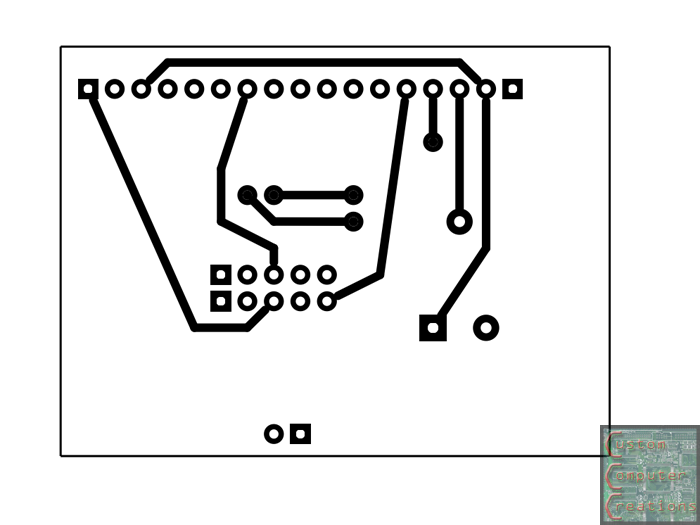
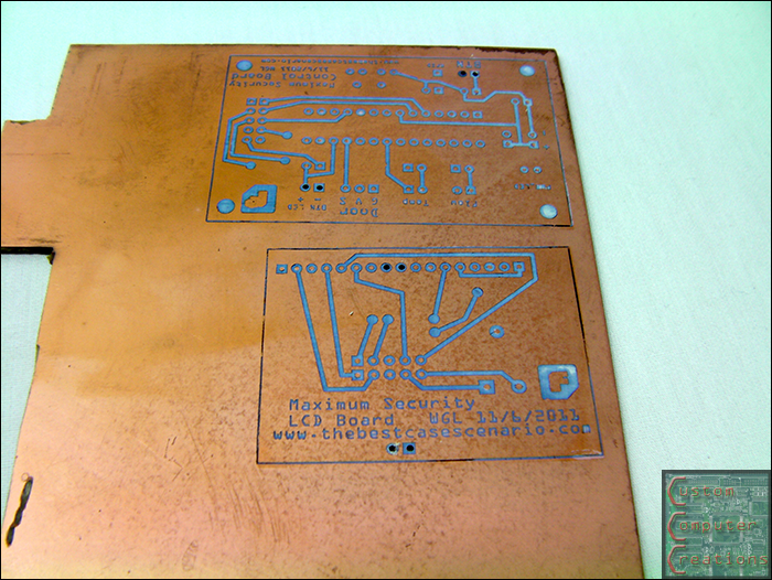
Here are the top sides all transferred.
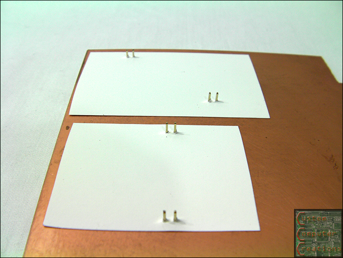
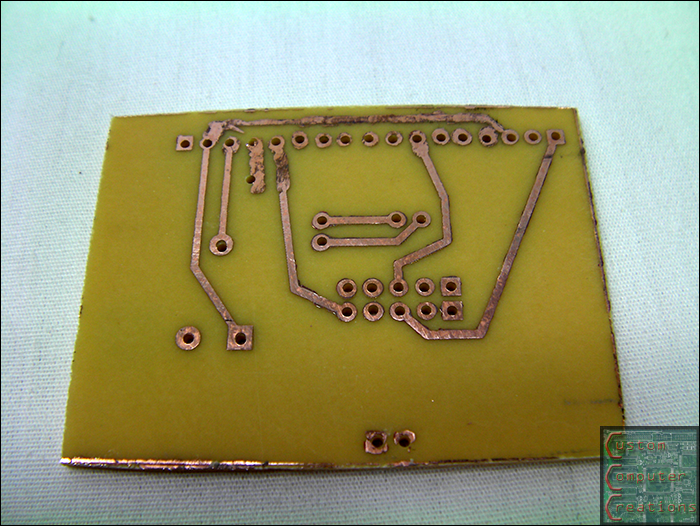
Here I've drilled a set of holes and inserted pins through them. I use these pins to line up the back side traces for transferring.
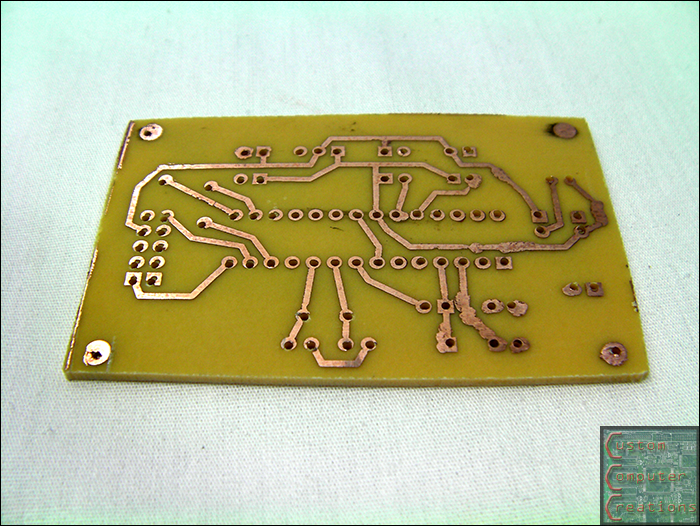
Fast forward a few steps and you've got a pair of freshly-etched and drilled boards ready for assembly! The blobby-ness on the traces is from a sharpie. If you get mostly good transfer but have a few little patches where it didn't stick you simply use a sharpie to draw it in. It works as an etch resist almost as good as the toner itself.
And here we have the pair of completed boards. I still need to test these to make sure they're working 100%
That's all for now!
Arctic Cat * Maximum Security * Cribbage Board * Rockin Case * Armor Redux
Tempest SXR * Power House * Red Comet * ICHIWZ * Acrylic Headphone Hook
Continuing sponsorship support from PCBoard.ca
 Posting Permissions

 Reply With Quote