Hmm.. I'd guess about the size of a Pinball machine!Originally Posted by AmEv

I'm totally jelly! Can't wait to see it progress Troy! Great work so far.


Hmm.. I'd guess about the size of a Pinball machine!
I'm totally jelly! Can't wait to see it progress Troy! Great work so far.


I see what you did there....
Arctic Cat * Maximum Security * Cribbage Board * Rockin Case * Armor Redux
Tempest SXR * Power House * Red Comet * ICHIWZ * Acrylic Headphone Hook
Continuing sponsorship support from PCBoard.ca
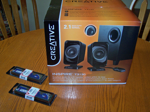
I decided to make a couple of hardware changes, first up I am ditching the 2GB of Crucial Ballistix memory in favor of 4GB of Kingston Hyper-X, because more is better and they are lower latency. Secondly, the Logitech speakers work great in my MAME machine, but they are right in your face. At 1.5w per speaker I can't imagine they'd sound as good four feet away, another negative is the volume control knob would have stuck out from the back glass. My new Creative Inspire T3130 speakers are 25w total with 5w each satellite and 15w for the subwoofer are a better fit for this project and the volume controls can now be easily hidden.
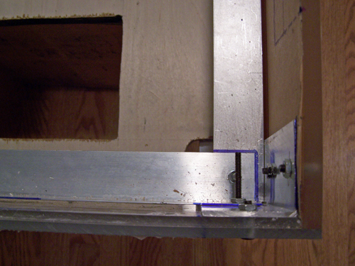
I finished drilling mount holes in the Alum-angle and then double side taped each piece onto the acrylic side panels to use as drilling templates. I have a set of drill bits that are specifically for plastic and acrylic and mention it only because they are crucial to achieving professional results when working on stuff like this... besides, it doesn't make sense to risk cracking a hundred dollars worth of 3/8" acrylic over a nine dollar specialty drill bit.
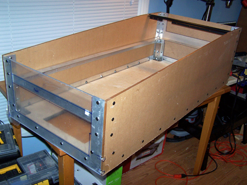
Here the side panels have been drilled and are mounted to the base for a test fit and everything so far fits good.
Below is the inner leg brace, since it fits tight already I only need to drill out the center holes on the side edges of the brace to permanently attach them.
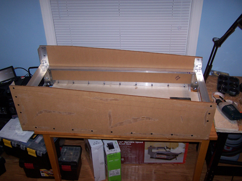
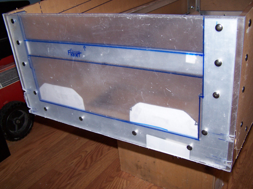
The back side panel is cut from pressboard and the first piece of the two part front panel is cut from a sheet of .220 Optix acrylic, below shows both attached for a test fit. I also bought a piece of black molding from a Williams wide body pinball machine that secures the back edge of the table glass, I cut it to size and it is sitting in place on the top edge below.
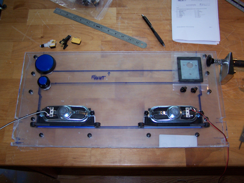
I cut the second piece of 3/16 acrylic sheet for the front panel, below shows a top down view.
The reason the front panel had to be two sheets thick will become apparent when I mount the speakers from the TV and the five recessed LED buttons. The two white pieces of paper show where I Intend to mount the TV speakers.
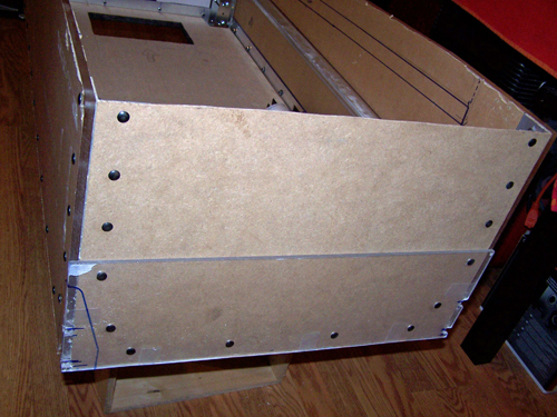
I had to thicken up the back material so that the pinball table legs will seat correctly, for this I used the same 3/16" acrylic as the front panels. Sadly, in figuring out that the thickness of the rear material mattered when mounting the legs I destroyed two bolts and a leg mounting plate, I am currently awaiting delivery of replacements.
Visit My Site: www.CaseModGod.com
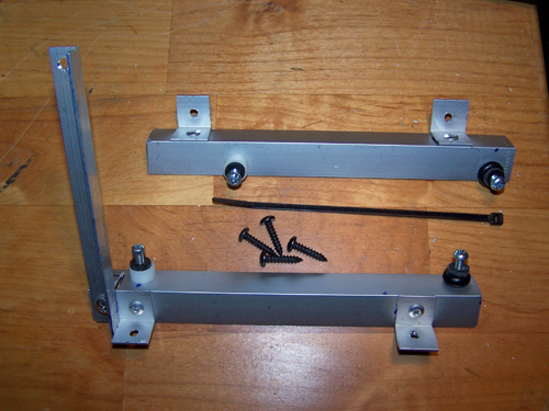
I cut and rivet together a few pieces of Alum-angle as the start of a simple mounting base for the motherboard and video card. The four screws will secure the motherboard to the wood base of the pinball table and the zip tie is there to hold the video card in place.
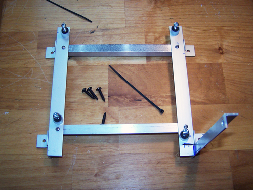
To prevent the motherboard from ever flexing I cut and bolt down a couple cross braces, I chose to bolt the cross braces on instead of riveting because if the motherboard mounting holes don't line up perfectly the bolts will adjust way easier than resetting rivets.
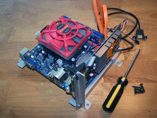
I installed the processor, CPU fan, video card and memory into the motherboard, I also plugged in a SATA cable, an external USB and I used an old four wire audio cable over the power switch and power LED pin-outs on the motherboard... this thing will be ready to be mount permanently in the cabinet after I install the OS, drivers and software.
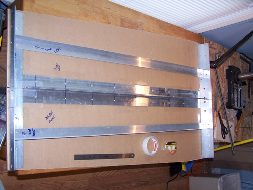
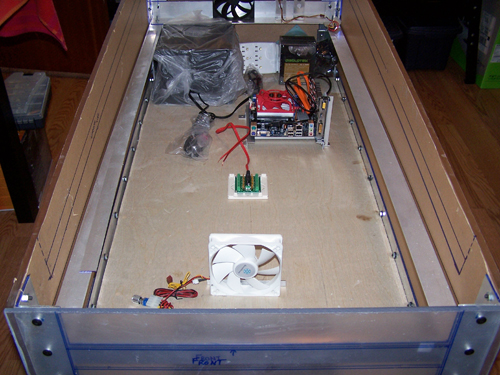
Next up is trying to find the best places inside the table for the hardware. I cut and drilled a strip of 1/2" Alum-angle and attached it to the bottom of a speed adjustable 120mm fan, it will sit up front and blow back. Sitting just behind the fan is a Logisys power distribution box, then the motherboard, and behind that is the 6 outlet surge protector and the power supply. The power supply will be ducted to the rear, as will the subwoofer (shown still covered in plastic).
Visit My Site: www.CaseModGod.com

So, when are you sending it my way???
@ AmEv... Um, I'm thinking never, besides it's heavy and shipping would be a bitch.
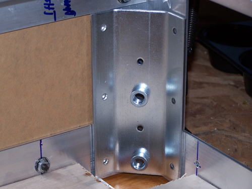
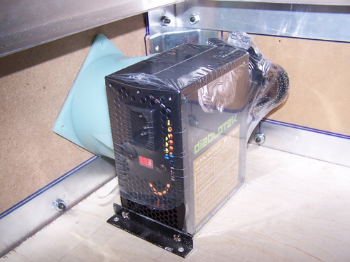
Alum-angle on the bottom of the PSU to mount it and a duct to the rear to provide cool air, I will probably also use some double sided tape on the bottom of the PSU to make sure it stays put as well as rubberize the PSU edge of the duct against vibration.
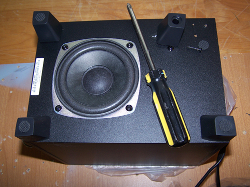
Off with the legs! Removing the legs from the subwoofer allows it to sit at nearly the same distance away from the pinball table interior side wall as it sat with legs... without interfering with a couple other things I have planned.
Below shows the three pieces of Alum-angle that I cut to secure the subwoofer, they will all be lined with felt to prevent vibration before the sub is final installed.
Visit My Site: www.CaseModGod.com
AWWWW...
Seriously, though, keep up the good work!


This is sooo cool Troy!
"At the midpoint on the journey of life, I found myself in a dark forest, for the clear path was lost..." -Dante Alighieri
I measured out where a few holes needed to be cut in the back panel and predrilled pilot holes using an 1/4" bit for plastics, then I run the hole saws first forward to cut the pressboard and then in reverse to cut through the acrylic.
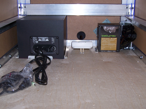
Below is the back panel with the holes drilled and the hardware that required those holes installed, everything lines up even better than I expected. The blue-green PSU duct will be vinyl dyed black and a black plug for the power cord was added after realizing that the hole I cut was the exact same diameter as the plug I had.
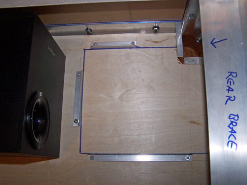
Next up is a look from the inside with the sub-woofer and PSU installed, since I no longer plan to attach the six outlet surge suppressor to the back panel I will need to figure out another way to secure it... a fair trade for how clean the back looks.
Visit My Site: www.CaseModGod.com
I decided to change the design of the front panel, so the white, green, yellow and red LED pushbuttons are now out in favor of only using the blue LED jumbo and small pushbuttons. Another two small black SPST momentary pushbuttons will be recess mounted below the plunger to act as the pause and exit to main menu buttons.
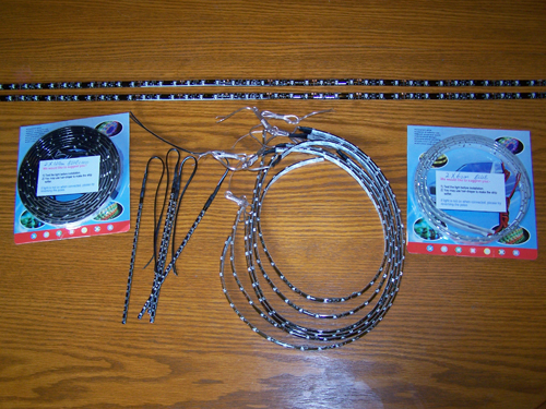
The build will now be themed totally in blue and black, why? Because I got a really cool idea that I couldn't shake about how to make the pinball machine really stand out visually without resorting to print vinyl graphics. Below shows one hundred dollars worth of blue 12v SMD LED strips in lengths from six to forty eight inches and flavors from chaser to flashing that I ordered from a seller in China, they will all be worked into the project.
I had to test them all to be sure they survived shipping so I screwed ten of them into the Logisys power distribution box. I really like the Logisys unit, it is made for powering video surveillance cameras, but works perfectly for this type of application. Also, I feel that I got more than my moneys worth of SMD LED strips, these bad boys are wicked bright.
If anyone is curious how the active LED strips look in action I made a video of the six inch chaser SMD LED strips and the twenty-four inch flashing SMD LED strips...
http://www.youtube.com/watch?feature...&v=r6u8dAHnwRY
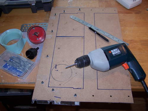
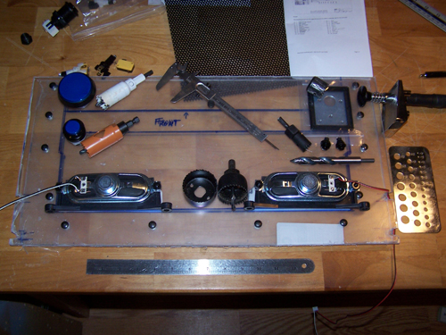
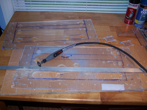
Back to working on the front... below shows the measuring tools, drill bits and hole saws that will be used to fabricate the two ply front panel.
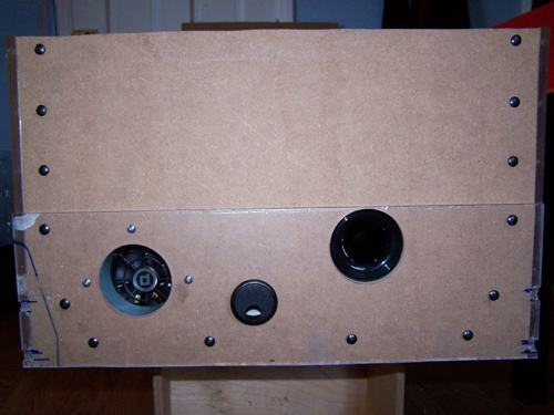
Here are the front panel pieces almost finished, I used the trusty Dremel flex shaft and a length of Alum-angle as a guide for the ripsaw blade to cut out the extra bits from the speaker holes.
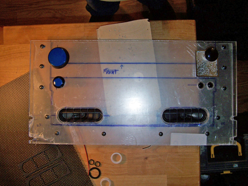
The front panel with the speakers, buttons and plunger test fit, I still need to cut some mesh and install it over where the speakers are going to sit.
Visit My Site: www.CaseModGod.com
 Posting Permissions


 Reply With Quote