I think the train stopped once . Cant remember where we stopped. Was round about 1991. I ended up in Bulgaria before running out of money. It was a railcard trip. I was young and mostly drunk throughout the trip!


I think the train stopped once . Cant remember where we stopped. Was round about 1991. I ended up in Bulgaria before running out of money. It was a railcard trip. I was young and mostly drunk throughout the trip!
www.Justblair.co.uk My depository for electronic projects and articles

ha haaa in '91 I had about 3 years))
Bulgaria is nice, i think they are starting to revive theyr economy
hope that after 2007 the EU would force some changes, the thing that gets me going about this is an easyer way for me to get to UK or france or maybe even get a job there.... but its a long way till then
LOUD AND PROUD !
Update...
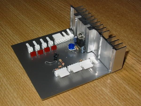
I finished the pcb. Mostly without trouble, but I had an issue with the power regulator. First of all the good stuff.
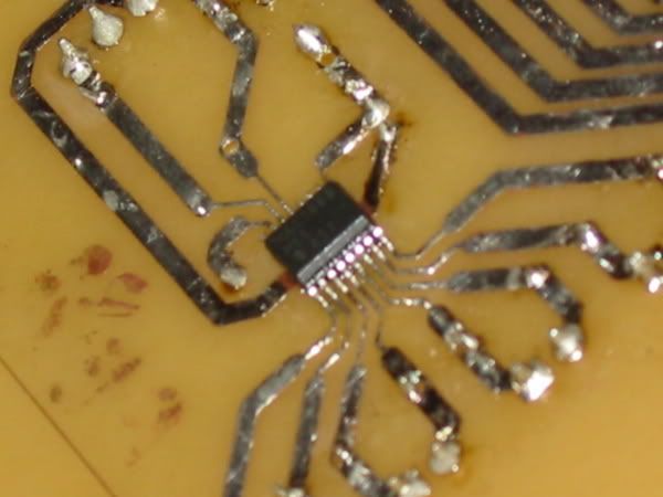
The temperature sensor worked straight away. Even though soldering the 5mm 16 pin soic looked terrifying, it was as easy, if not easier than the through board solders.
Here is the Maxim 1668 in all its glory! This is my favourite part, it looks so difficult to do, but it really isn't. From now on I'm doing surface mount stuff in all of my projects.
Tested it first, and the local sensor worked first time. I checked it with a medical thermometer, and the accuracy is better than the +/- 1c that maxim quote.
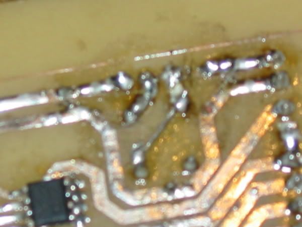
Here is the reverse side of the PCB. The 24LC21 chip is there as well. It worked first time as well. Though I haven't got it programmed yet to the right settings, it is accepting programming and is reading correctly by the matrox card.
You can see also that I tinned the copper traces with solder. Cleaned them fluxed them and then drew on a thin layer of solder. In real life you can't see the imperfections.
Now the gory bit. I tried the power regulator, but all was not well. It could be adjusted to the right voltage using an adj resistor. Then when I plugged the psone screen in, it just didn't light up... Bugger.
After posting for help on SPCR someone pointed out what was wrong. I had followed the manufacturers diagrams for the regulator. However the diagrams had the wrong pin assignation on them! How stupid is that? Then I had an issue. Do I start again? Do I keep the mostly working pcb and build a power regulator seperately?
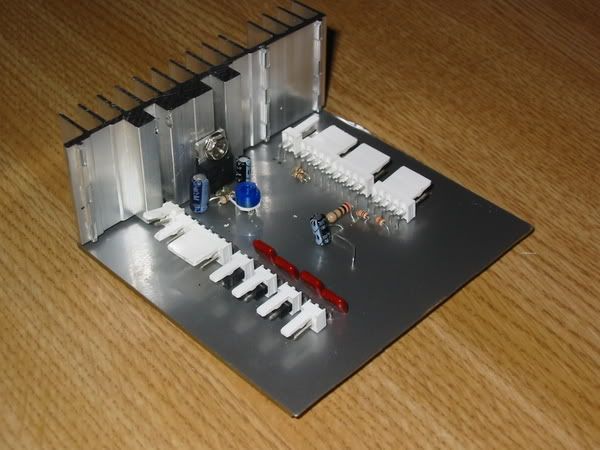
Nope. I had another plan. I tore up a couple of tracks, inserted a couple of jump wires and lo and behold I had a working regulator. On the printed side (above) of the pcb it is a little messy, but on the side that will be visible, you can hardly tell the difference.
Then I attached a heatsink to the regulator. It was a heatsink from the first ps2 that I killed (technically sony slaughter... I didn't mean it your honour)
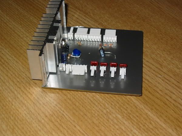
I also had in my cupboard some adhesive vinyl that I purchased in Hungary on an impulse (that will be usefull for something) purchase in March. This I used to coat the non tracked side of the pcb. It silvery, but non conductive. I think it adds a touch of class to the component side of the board, which will most likely be visible when I find a place for it. The result I am most pleased with... Check it out...
The other thing I am happy with is that I finally worked out how to use the camera... No more blurry closeups!
Now I have to come up with a creative way to mount it. That heatsink is live... Its only 7.5v so its not dangerous, but it will have to remain isolated from the chasis of the puter, I get sparks otherwise!
***Edit***
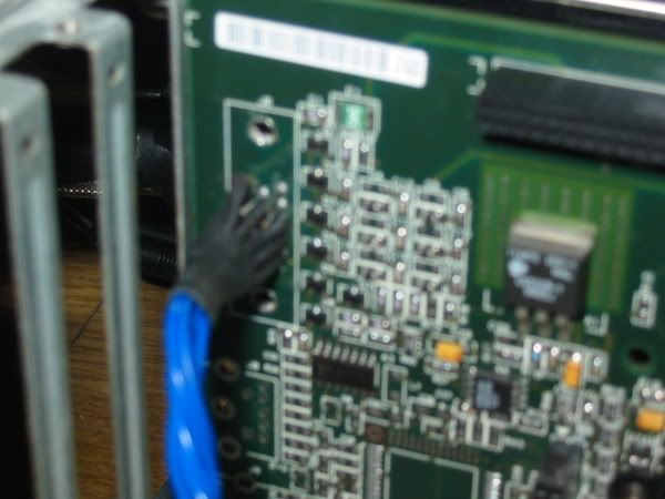
I completely forgot to say... I finished my mod on the matrox graphics card as well. As mentioned before I attacked the vga header with a hacksaw. What I was left with were 15 pins. I soldered some single core copper wire to these pins and at the other end added molex connectors to attach to my PCB. Here is the result...
This means all of the psone screens wiring is now held inside the case. I attached enough wire that I can hide it when it comes to final build time.
www.Justblair.co.uk My depository for electronic projects and articles
ZOMFG thats a big heatsink. i love the covering on the pcb. great job man.
Its not really that big a heatsink, the cards pcb is 8x9cm the heatsink is 9x2x3cm.. Its bigger perhaps than I need. (it gets hot though) but I err'd on the side of caution cause its going to be in a passive system.
The vinyl I am pleased with. Haveing looked in the photos it looked like it had a couple of tears in it. Have checked and to much relief, that turned out to be a couple of pcb shavings.
l
www.Justblair.co.uk My depository for electronic projects and articles
woooow great job dude, it looks so damn pro!
the vinyl ads a lot to the whole thing
LOUD AND PROUD !
Well this update has been a while coming....
So what have I been up to?
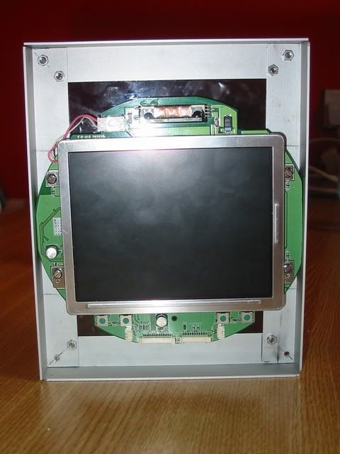
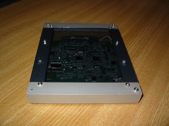
Well. I built a mount for the psone screen. This I made out of alu L brackets. Finally got to use my drill press in anger... What a usefull tool it is.
Basicly I made a rectangular box. Then using four bolts through the screens mounting points I had an adjustable (for depth) mount.
Here you can see the psone mounted (ooh err).
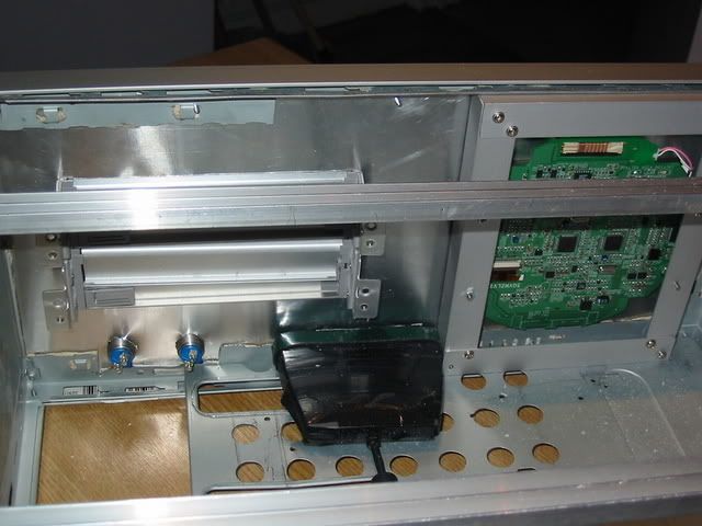
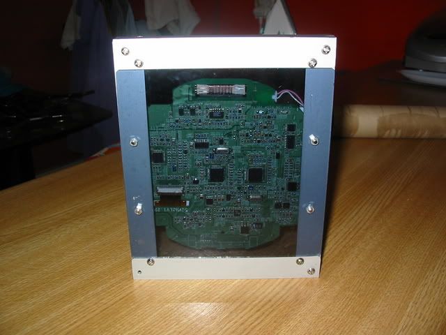
And one from behind (double ooh err!)
When I fired it up, nothing happened... I had damaged the cables at the molex end going into my homemade pcb. The problem (I found after spending an hour with a multimeter) is that the psone screens cables are very fine. This was a relief, as to get the right clearances I filed off about a centemetre of the screens pcb. On the right of the pcb is a lot of ground plane, this is what I removed. I have a plan to make a more durable connection which is yet to be executed. I did though get it working.
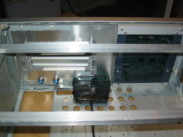
When it was lit up I noticed something that had eluded me before. The backlight of the screen shines through the pcb highlighting the gaps between the tracks. This i thought had to be exploited. So I made a cover for the back. i used 2mm thick perpex then covered it in a smoke tint film (the kind you get for car windows).
When I get the power to this, I think it will look pretty damn good.
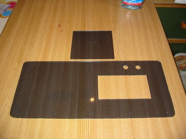
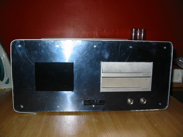
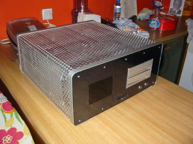
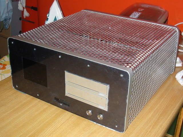
Next on the things to do list was a front panel. This is made of a very thin sheet of alu, then a sheet of perspex in front of it.
There was a lot of cutting and shaping to do to both layers. On the perspex there is a hole cut for the drive bay covers (lian li) plus two stainless steel buttons which will be the power buttons for the pc and the playstation.
I also drilled and counter sunk some screw holes top and bottom to hold the facia onto the case. I had considered glueing, but the countersunk screws I think look cool. It would perhaps have been a bit bland otherwise.
On the alu I did the same plus cut a hole for the psone screen and the remote sensor. Here is the result....
The scratches are on the alu sheet behind. There are still some bubbles on the tint, but I am hoping that they will disapear as it dries out.
I am pretty pleased with the result. There is a whole lot more to do, but I think that the front panel is getting to the point where you can imagine how the finished case is going to look.
The alu will be spray painted black. This should make the psone screen and the IR sensor disapear behind the smoked perspex.
On the to do list now.
1. A side panel needs to be manufactured with the PS2 inputs, Usb ports and two rotary switches (with alu dials of course) which will switch the usb (between the PC and PS2) and switch the lights and psone screen on and off.
2. A base needs to be made. i have a set of sorbothane feet already. Some of the base will be meshed.
3. I have a sheet of perspex mostly cut to sit on the mobo tray where it is exposed. i will cover this in some more of the silver sticky backed plastic. The pcb will mount to this.
4. I will have to redo the ps2 controller extensions to take into account the new location of the psone.
5. I have to build a new mount for the ps2
6. I still have some tidying to do for the case lid, including screwing it all together. I plan to use countersunk screws in the alu bands. I also have to put a final strip in on the front at the bottom.
Ideas are still welcome even at this late stage?
www.Justblair.co.uk My depository for electronic projects and articles
Amazing. I'm just blown away. I've been following since day one, keep up the good work.
Currently under work: Xbox/PC Hybrid Tower
CZTR Series Queue Line:
Shuttle XPC
Dell Inspiron 3800 (Yeah a laptop)
SGI O2

lol Mean Lean Grilling Machine. Nice.
Coffee is love, coffee is life.


This mod kicks some serious ass. Great work with the circuitry, i'm rubbish at Soldering. I'm hoping to improve over time with practice.
Well done with those tiny little pins though, how you managed that, i'll never know.
-Dave
Originally Posted by jdbnsn
 Posting Permissions

 Reply With Quote