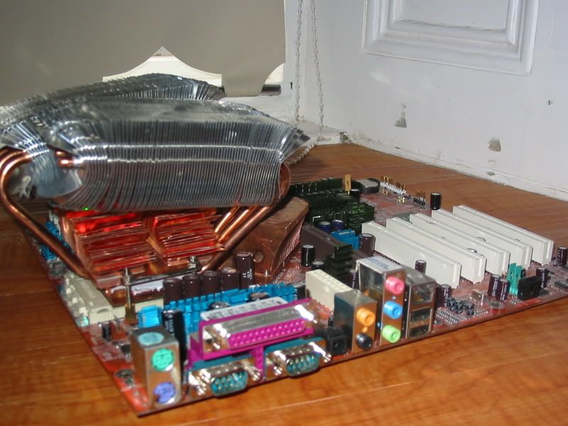
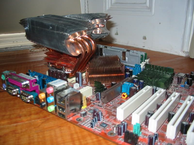
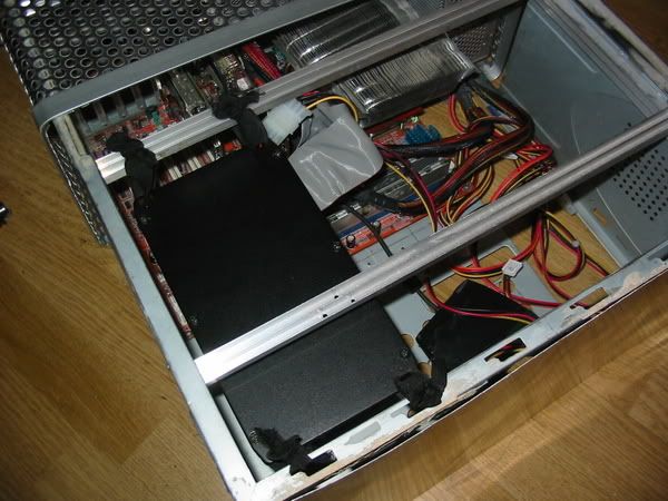
Ok the tea didn't do me any good the other night. But I look through my albums to see what I had. Here are some photos of the mobo, cpu cooler mods.
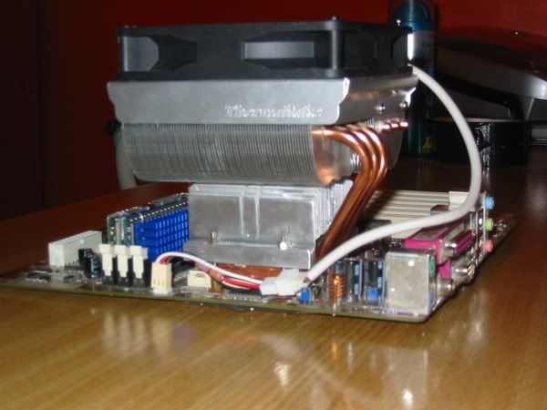
You can see in the pictures that there has been quite a few mods made to the mobo and also the TT big typhoon cooler. I didn't take pictures as I went along, so this is just a finished result. The mods are.
Mobo.
Cut up 2 pII anodised heatsinks. The bits were used to add cooling to.
Green one
The southbridge of the mobo
The power regulator for the graphics card
For the southbridge I had to trim a chunk out of it to allow the graphics card clearance. By happy coincidence the chunk that was trimmed was the right size and shape to sit on the power regulator without fouling the card.
Blue one.
The power regulation section of the mobo
The power regulation for the memory
Any other chips that were hot to the touch.
This got really cut up. I shaped it initially to fit on the mobos power regulation mosfets that control vcore etc. There were 5 (i think) mosfets to cool, but the snag was that they had caps sitting between them. I trimmed the cpu cooler to fit around the caps. It actually is 2 pieces of alu, but lined up to look like one.
The remaining pieces were used to cool any other mosfets or hot chips that I could find on the board.
All the alu sections were attached using double sided thermal tape. This I would say is an extreme mod to do, I know that overclockers have got some extra mhz by cooling the mosfets. In my case though i was out to ensure that passive operation wasn't going to cause instability in the system.
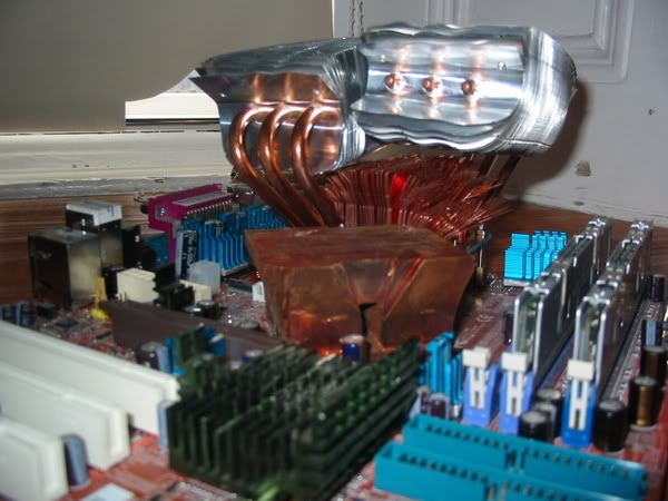
The northbridge needed a bit more...
For this I took an evercool pure copper 6cm heatsink and trimmed it down to clear the CPU cooler. I attached it by using self tapping screws (and plastic washers to spread the tension and insulate) throught the 2 origional mounting holes. It replaced a whiny little fan that was standard in on the Abit NF7 mobo.
I dont know how much of this modification stabalized the system. I do recall that the vcore fluctuations were more stable when viewed on speedfan, but as the system was stable before, I cant say for certain that this more stable vcore made much difference. However this whole setting up phase was done in free air, so perhaps I avoided some problems later.
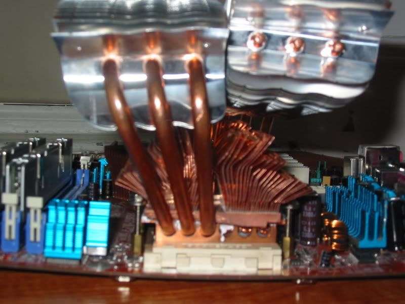
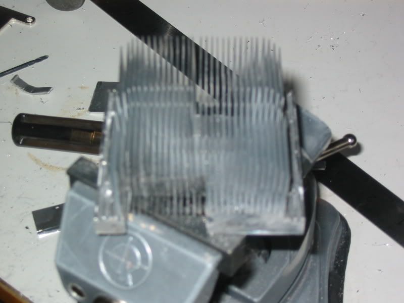
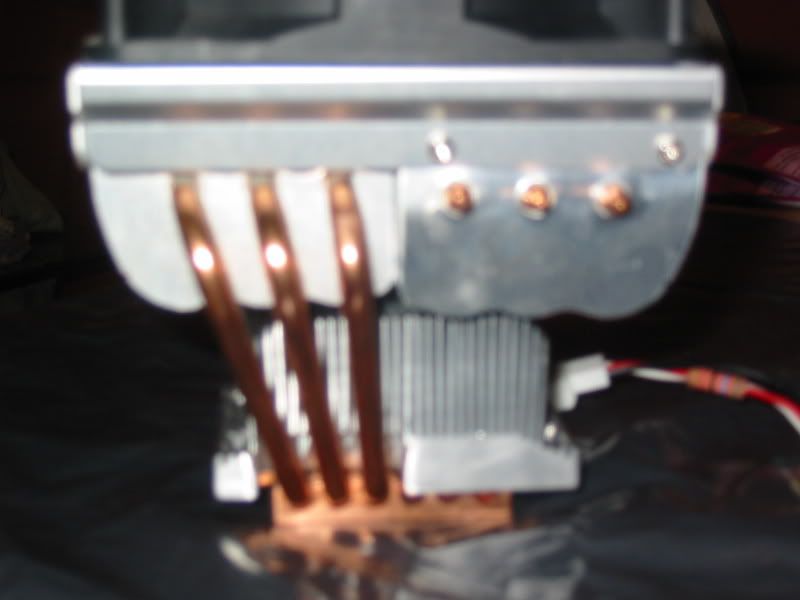
The Typhoon is another story. I used a tt 8cm copper core from a volcano cooler. Shaped its base, removed the bracket system from the base of the typhoon and attached it to the base. The fins were bent to make it fit. I also bent out the heatpipes, and the alu fins to allow as much fresh air in as possible.
Overall I am not happy with the aesthetics of this, though the mod certainly is a practical one. In free air in my passive config It reduced the idle from 49c to 40c and reduced the load temp from 53.5c down to 48c.
When you are working passive systems any sort of drop in temperature is difficult to achieve. The system runs at most of the time below 40% cpu useage when running MCE. So this made a big difference to the temps. At the time I was running the processor at 1100mhz. This mod gave me another 100 mhz of clock speed whilst the sytem remained stable.
************************************************** ********
Just to show the process, here is a step by step of my second attempt.
I did this mod a second time, this time with lessons learned. This is the worklog for the second typhoon. You can see how much better I got this second time roundThis one sits in my desk pc, but I may redo the one for the passive pc if I can find a donor heatsink. I got a better result, the mounting system is much neater and I think the airflow is better.
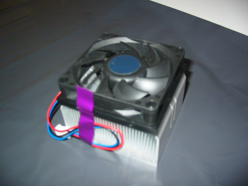
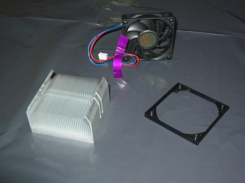
To begin with I started with a standard Athlon XPx2 Cooler. This cost me nothing as it came supplied with a processor being used elsewhere in the house.
Here as you can see it is disassembled and ready for modding.
The fan and the bracket are heading for the parts bin.
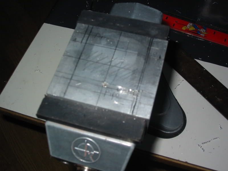
Next I marked up the base of the donor ready to be shaped. This will start to make sense when you see the Typhoon ad the donor combined. The section on the base marked pipe needs to be removed, This is to clear the heatpipes on the Typhoon when the donor is placed on top of the Typhoon's collecting plate.
You can see in this picture I have started to drill a line out to remove the pipe section.
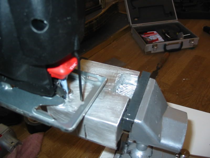
I used a jigsaw to cut away more of the base. This was far quicker than drilling. I used the fins on the other side as a guide. You can see on the other side the desired result.
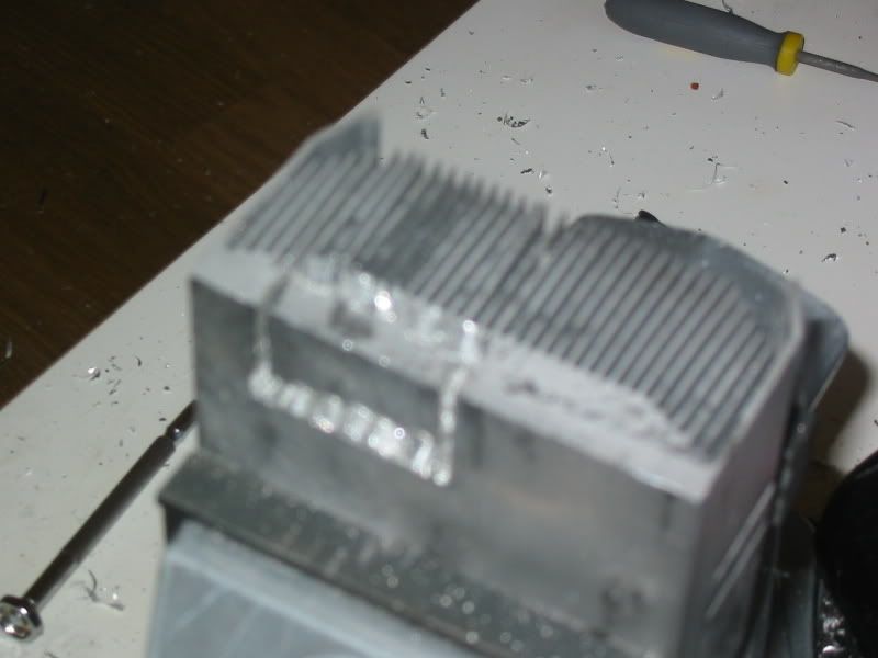
You can see through the glare on this picture the heatpipe section cut and drilled. Ready now to pop it out. More drilling is required to do this.... .
Here you can see I drilled down from the side, near the fins (Sorry the camera doesn't like closeups). Then I used a set of precision files to join the drill holes. Eventually a nugget of Alu fell out and I had clearance for the typhoon pipes.
Next I had to produce a way of mounting the two heatsinks to each other and to the motherboard. The Typhoon normally uses a H plate to mount to the Mobo. In my previous mod I had retained this mechanism as you can see in this picture..
This time I didn't want to cut a slot, I decided that the best way forward was to shape the donor heatsink so that it became part of the mounting mechism. I removed the fins at each end of the heatsink to create a flat surface that replaced the uprights of the H shaped mount. (Kinda hard to explain, the phots make it clearer)
I drilled holes for the bolts through these flat sections and filed clean the cuts. A bit of sandpaper was used to clean away as much tool marks as possible.
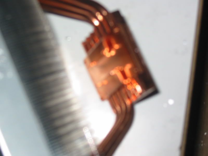
Next I had to prepare the typhoon. On the heat plate, there is a copper cover that holds in the heatpipes and also provides a guide for the H bracket. This had to be removed.
First there are 4 Jewelers screws that come out easily with a precision screwdriver. Next the Bracket has to be prised off as it is bonded also. To do this takes guts. I first prised open a gap between the bracket and the plate below. Then out comes a chisel. Holding it flat against the plate I gave it a gentle tap. The glue released and hey presto I have a cooler minus bracket. Sorry i have no photo, Both hands were occupied with the heatsink and chisel. If I had a third hand it would have been wiping the sweat off my brow!!
Fortunately the glue holds the heatpipes in place.
Next I applied as much TIM as I could find in my spares bin. The picture above was taken about half way through. I used about 5g of the stuff. I glued in a couple of strips to the open ends of the pipe grooves so I could hold more TIM.
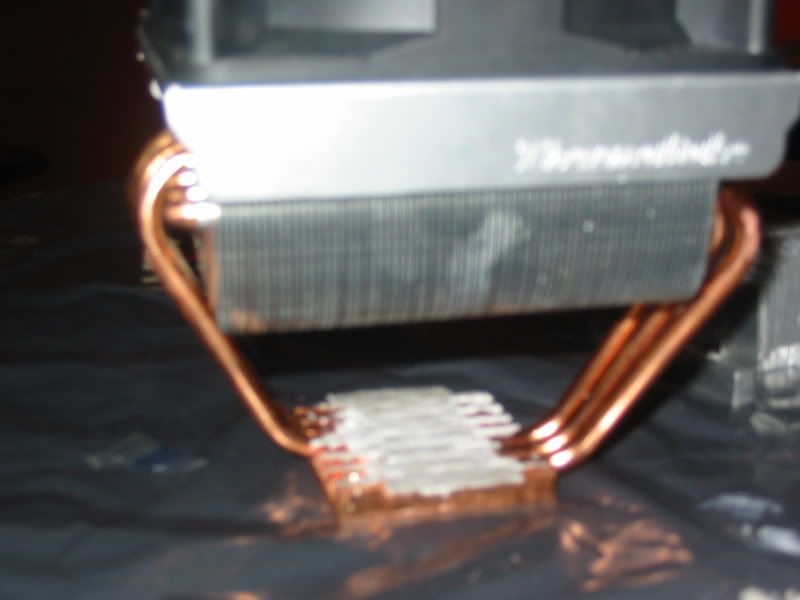
Now it was time to join the donor and the Typhoon.
The fit was good. All that had to be done now was to bolt the modded typhoon onto the mobo. The bolts hold the whole assembly together.
Attached the fan to the mobo fan header then fitted. You can see also the inline resister that I added to slow the fan down. The results were as follows..
Initially I tested the cooler outside of the case. This yeilded the following...
The processor is an Athlon 3000XP it throws out 90w plus of heat at full load
Before...Idle 34c Load 39c
After...Idle 31c Load 36c
The results were a little marginal, around a 3c drop (6f) both under load and idle. I was a bit disapointed. However when the mobo was fitted back into the case the work became a lot more worthwhile...
Before
47c idle 59c+ load
After
37c idle 47c load
Massive success when the cooler was tested in its intended destination. The PSU fan is in close proximity and it would appear that
a: The PSU is drawing air through the donor,
b: This design is more useful in higher temps.
************************************************** *********
Now to clarify a point before it is questioned.
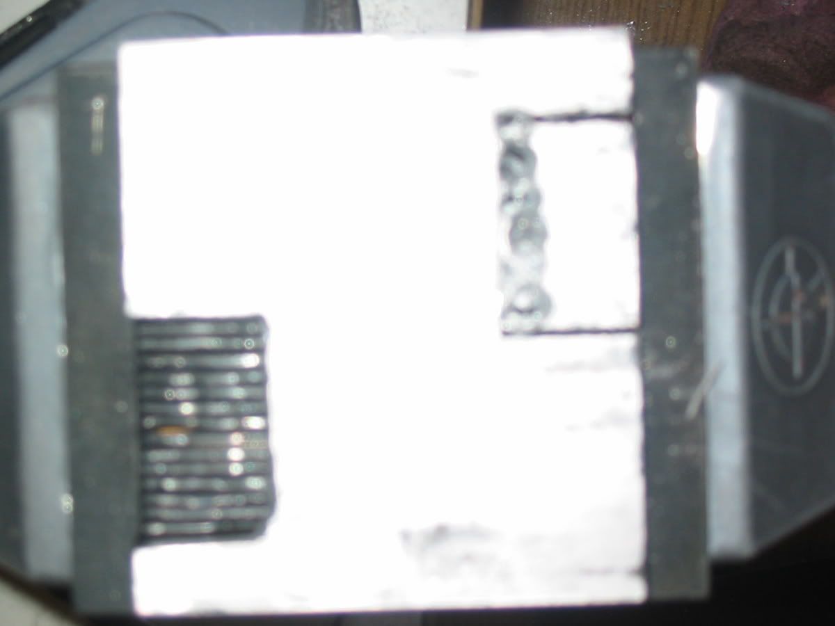
My camera does some weird stuff in closeup shots. The first modded pictures appear to show a huge bend on the mobo. In real life their is a very small amount of distortion (caused by the Northbridge heatsink), the camera makes it look like a massive bend.


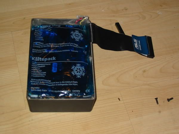
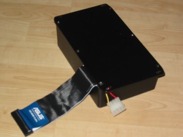
 Lid on the box and fit the screws. Be carefull that you dont burst the bag of Gel as you do this....
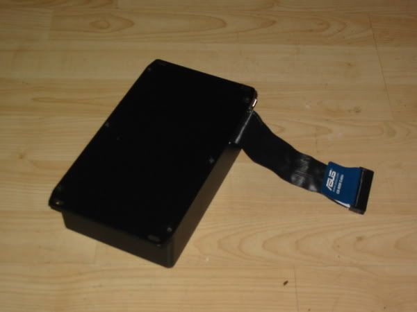

 No refund...