


Hi all.
Been checking this site out for years, but this is the first time posting.
Decided to start a project building a mini-ITX case sometime back, and to contribute whatever I've done so far. This thread will contain about.... 1-2 months work
Also, will need a name for this project
Btw, this isn't a how-to (I'm just not qualified to post a how-to), so only the most relevent parts mentioned. Besides, I think you guys are sick of all the pics of drills hitting metal, or an essay about aluminum filing techniques...
The reason
I don't know if you guys need a reason to mod, but I don't have any experience building things from aluminum. Or wood (other than whatever you learn from school). I don't have anyone to go to about this neither, so everything done here is either learnt from the net or improvised someway. I don't own any metalworking tools, nor do I know someone who has any, so this was going to be an expensive project, but I'd get to keep the tools for future use.
My first reason is the lack of an enthusiast mini-ITX case. Sure, we've got the Silverstone SG05, but that case doesn't take everything I want to throw into a computer. It uses slim-optical drive (not a biggie), custom PSU (biggie), and only 78mm clearance for an aftermarket CPU cooler. 78mm clearance?!??
The specs
1. Fit a mini-ITX board.
2. Fit a full, tower size CPU cooler. For overclocking, and quiet operation.
3. Fit full ATX sized PSU. I've set the length of this PSU to 14cm, which is the length of my current 650W Antec PSU.
4. Fit my current graphics card (GTX 260).
5. Fit 2x 3.5" HDDs.
6. Fit 1x 5.25" Optical drive.
7. Fit a 120mm exhaust fan or bigger.
As long as my case will fulfill all the above, I am happy.
I did some calculations, designed a layout by researching what works and what doesn't, and came up with this sized box (excluding the front bezel): 230x200x340mm.
That seems to be the smallest I can make it to fit everything in. It is bigger than any mini-ITX box out there that I could find, but I'm basically getting an ATX box with a mini-ITX mobo. And it will still be much smaller than mATX boxes out there.
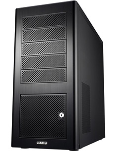
For comparison, Lian Li has a PC-Q07 case 193mm x 280mm x 208mm which doesn't have space for a massive heatsink, no space for dual slot graphics card, only 1x 3.5" HDD, and the overclockers nightmare, no exhaust fans! In fact, no case fans at all!
And another comparison case would be the Lian Li PC-V351 which is a mATX case, measuring a whopping 279x262x373mm. And even then, I have doubts about that massive heatsink.
(technochicken, if you're reading this you'd know I copied and pasted this from somewhere else)
The idea
I'm no good with paint/photoshop, so I can only provide a word picture for now. As I said before, I'm halfway through, so you'd be able to see what I've done anyway. However, what I will be describing was the original idea. A few things have since changed.
This is a cube-style case, with the motherboard sitting on the floor, toward the back of the case. This gives us about 190mm clearance from the top of the case. Given that the motherboard is 17cm wide, and the case is 208mm wide, nothing else will be sitting beside the motherboard. On top of the motherboard will sit 2x 3.5" HDDs side by side.
Where is the PSU? Sitting in front on the floor. Exhaust for the PSU would be through the front. As an overclocker, the last thing I want is for hot air to recirculate. On top of this would be the full length optical drive. A power cable extender will allow me to power the computer through the back.
That covers it.
WORKLOG
Here's what everyone's interested in I think.
The aluminum angles I will be working with. 20x20x1.6x1000mm
Also seen is the Ozito rotary tool. I bought it just for this project, and it died on me in less than 3 weeks. The shop (Bunnings Vermont South) refused warranty because "I used it too much". After 1 hour arguing that tools should last longer, I simply went to another branch which honoured the warranty, and allowed me to get a real Dremel (the only other brand) with the store credit.
A bunch of angles 45 degree cut.
My idea is to join this together to make the frame for a box. Given that I probably would affix everything to this frame, it should be as sturdy as I can make it. Not taking any chances here.
Here's some of the joined pieces
As you can see from the above, I used steel 90 degree reinforcing plates, which are riveted onto the aluminum angles. There are probably better ways of doing this. I would weld if I know how to.
Also, you can see that its far from a perfect joint, with space in between.
Another problem also cropped up. There are little pieces of steel left in the rivets which rattle around when shaken. Small problem, I just picked up a glue gun and filled all the rivets with glue. Problem solved in 2 mins.
Due to work and power of procrastination, the next pic is about 3 weeks into the project. I blame it on the need to swap the ozito for the Dremel.
The frame is actually very sturdy. I expected a need to reinforce it form warping or moving, but the thing is like a brick and won't give an inch no matter how I tried to bend or twist it.
No, I did not try sitting on it.
But my reasoning is that I haven't sat on my computer ever anyway.
Moving on.
Needed a way to affix the PSU onto the frame. I decided to lift the PSU off the ground by about an inch for space to stash stuff. I was thinking more on the lines of extra cable or front panel electronics rather than hash or pron, but whatever rocks your boat.
There will be a bar at the back of the PSU to support it's weight.
It was about this time that I realised cutting aluminum generates alot of heat... Notice that the sticker was burnt. This doesn't affect the aluminum in any way, other than make the sticker easier to remove.
More work on the frame. You can see from the next pic, there is a "seat" for the motherboard tray, and the back bar for the PSU. In the front (second pic), there is a "shroud" to prevent PSU exhaust from coming back into the case. A front panel will cover this.
If you're still wondering what the back bar I'm talking about, here's a closeup of one end. Exactly the same on the other end. It (and everything else other than frame) is held to the frame by epoxy glue. Epoxy glue is very strong. I can probably use it instead of the rivets, and definitely strong enough for computer internals.
And here's some pics with the PSU.
Similar thing for the optical drive.
Thats all I've got to share for now. As I said, its only about 2 months work, and more is to come.
Side project
"Wha?!? Didn't you say thats all you have to share?!?"
Yes I did. I lied.
Sometime between the start of the project, and now, I decided to incorporate a few things into the front panel. For one, I'd like to have PWM fan controllers built into the front panel. I'd also like to be able to flick a switch, and turn off ALL the lights in the case, without turning off the fans (the controllers can take care of that). This means, a simple switch in the circuit isn't gonna cut it.
Gathering what I remember from Physics in high school, transistors was what I needed. However, I never really learnt how to use them, and so I needed some way to test all my circuits (including the PWM controllers). This meant a desktop power supply.
Having none, and the commercial ones are too darn expensive. It was AUD$50 for a simple 12V source, and I also needed 5V. Those with dual power sources were much more expensive. A quick google showed me how to convert an ATX PSU into a benchtop power supply.
No instructions here, but you can easily google for them.
Initially, I was supposed to use an old P4 PSU. However, I did mark that PSU as obsolete, and showered it with aluminum dust. After conversion, it worked for 5 mins and died. So then I had to buy a new PSU. Here it is, for all of AUD$19.
You can't quite make it from the pic, but its supposed to be a 680W PSU. I wouldn't even power my HDDs with it really. The old PSU which is 430W actually weighed about double. And that was a crappy came-with-a-case PSU.
Here's the same PSU.
And here's my mods to it.
Well, the color of the connector represents the color of the wire I connected it to, except for the green, which was supposed to be orange. However, I didn't have an orange connector.
2 LEDs. Bottom one comes on if the unit is connected to a 240V source, and the top one is the actual power LED.
Thats all I've got to share. Not bad for a first post?


 Reply With Quote


 I've used my computers for chairs, tables, shelves, desks, and even structural support for shelves and/or other computer.
 .
.

 so far left of center i'm in right field