Page 1 of 3 123 LastLast
Results 1 to 10 of 21

Thread: Coilgun

  1. #1
    Will YOU be ready when the zombies rise? x88x's Avatar
    Join Date
    Oct 2008
    Location
    MD, USA
    Posts
    6,334

    Default Coilgun

    Yes, the project that has gotten me more weird looks at work than when I told them I was going to an anime convention, my coilgun project is finally officially starting.

    I've been dabbling around with figuring out some stuff for a while, and I decided it was finally time to start a worklog.

    First off, for anyone not familiar with the concept, a coilgun is simply a linear magnetic accelerator. In the simplest system, a single-stage coilgun, a ferrous projectile is loaded in place into a barrel/trough/whatever behind an electromagnetic coil. Current is then passed through the coil, generating a magnetic field, which pulls the projectile towards the center of the field (ie, the center of the coil). Ideally, the current should then be cut off exactly as the projectile reaches the center of the field, thus transferring as much energy to the projectile as possible. Generally, however, the field is active for such a short time that it does not matter (the reason for this will be discussed later). A more advanced version of a coilgun is the multi-stage design, which uses multiple coils in series, each accelerating the projectile further.

    For anyone who is confused or couldn't be bothered to read all that, here's a great animation showing a multi-stage coilgun in action (thanks wikipedia!).


    A high voltage must be passed through each coil in order to generate the required magnetic field. This is normally achieved by using a bank of capacitors to build up a large charge over a (relatively) long period of time from a much lower voltage power source. The capacitor bank is then discharged instantaneously (or near enough as makes no difference) through the coil, creating the magnetic field.

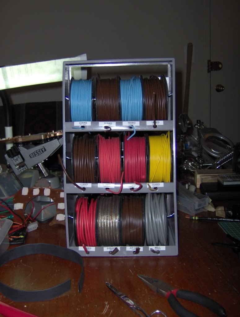
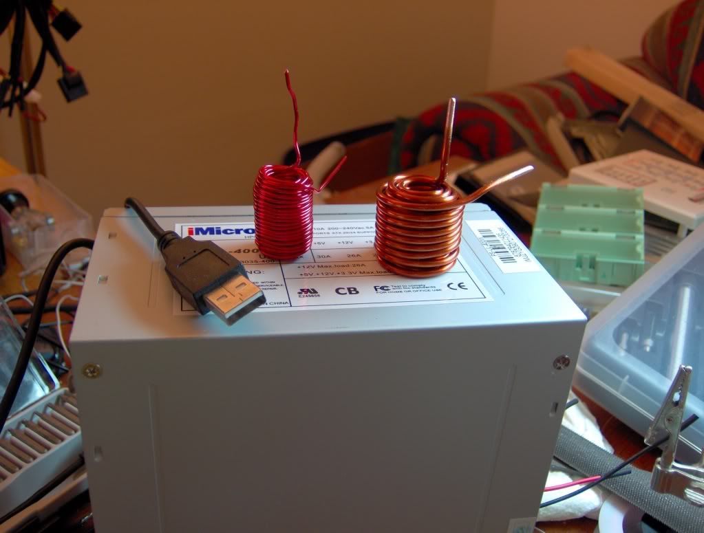
    I started off winding some coils for testing. Both are 1.25" long, but one is 4 layers of 12AWG magnet wire, and the other is 4 layers of 18AWG magnet wire. For anyone unfamiliar with magnet wire, it is simply a single, solid strand of copper coated with a thin layer of enamel. This makes it ideal for winding electromagnet coils (thus the name), because it allows the space between each strand to be almost negligible. This is important for some lovely equations I'll probably go into later, but suffice it to say for now that it lets you get a stronger, more compact coil, using less wire.


    There are many different coilgun designs floating around the internets, but they generally cost obscene amounts of money to create, or are based solely on the capacitors and charging circuits out of disposable cameras. Now, this is all well and good, especially if you can get them for free, but through some Electronics Goldmine surprise boxes, I came into a crapton of 330uF 35V caps, which I'll be using for this.

    This also puts me in the position of needing to make my own charging circuit, but from my reading around, the charging circuits out of disposable cameras tend to be rather...s***. They work well for a while, but if you use them too much or try and pull too much out of them, they tend to, well, fry. So, after much searching, I finally found information on building a cap [bank] charging circuit, which actually turns out to be remarkably simple. I found a schematic by one rwilsford07 in this instructable, interestingly enough developed for the same reason. This was great, but it took a bit more talking with a couple EE friends to learn exactly what was going on with the inductor.

    So, class time again. (The guy who wrote the instructable I linked above has a very in depth explanation of his circuit there, but I'll give the lite version.)

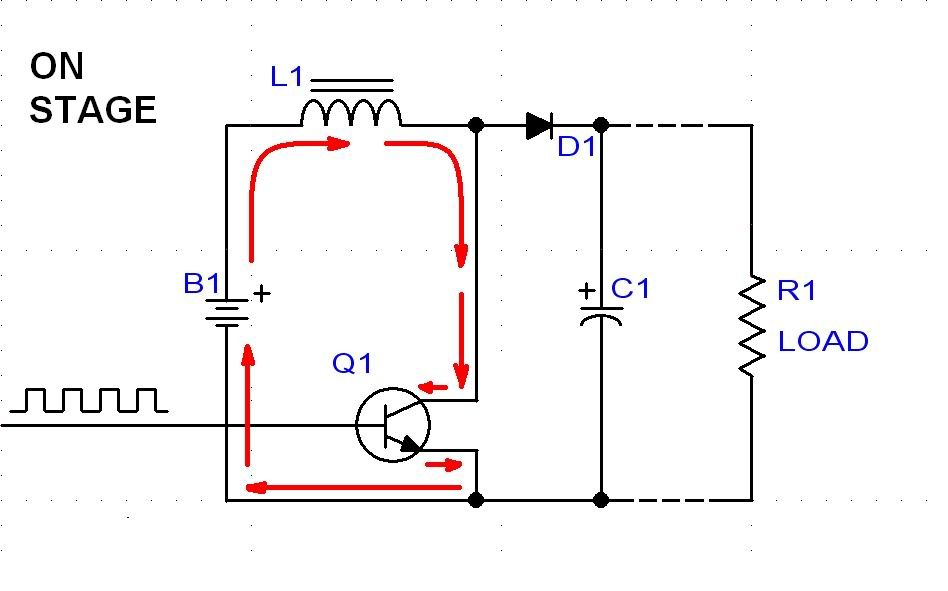
    We start off with the circuit like so (current follows the red arrows), with the transistor conducting.

    Disclaimer: This and the next image I'm mirroring from Intructables to save their bandwidth from cross-embedding. They were created by the same guy again, not me.

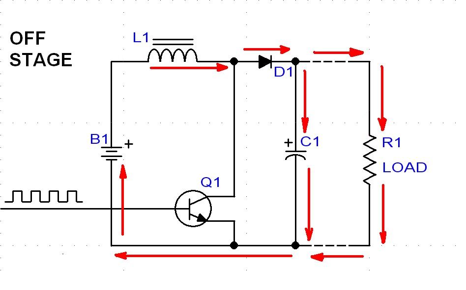
    In this state the power source is feeding into the inductor (the thingy at the top), creating a magnetic field to store the power. The path of least resistance is across the closed transistor, forming a simple loop and not touching the cap at all. The transistor is then switched off:


    In this state the power stored in the inductor is dumped into the cap.

    The signal coming from off-screen left is a square-wavesignal from a 555 timer IC. The result of this is that transistor is turned on and off very quickly, speeding the charge of the capacitor(s).

    Like I said, a 555 timer was used in the original design, but I don't have any right now so I'm gonna be testing different timings with a microcontroller I have to see if there's any difference. I'll probably end up just putting a 555, but I have the capability and I'm curious.

    The problem I ran into that some of my EE friends cleared up was whether the inductance of the inductor mattered at all, but it turns out that, well, it doesn't. Think of it like the battery is a hose filling up a bucket (inductor), that is then used to fill up a swimming pool (capacitor(s)). No matter what size bucket you use, you'll fill up the pool eventually. You just might fill it up a bit faster with a larger bucket.

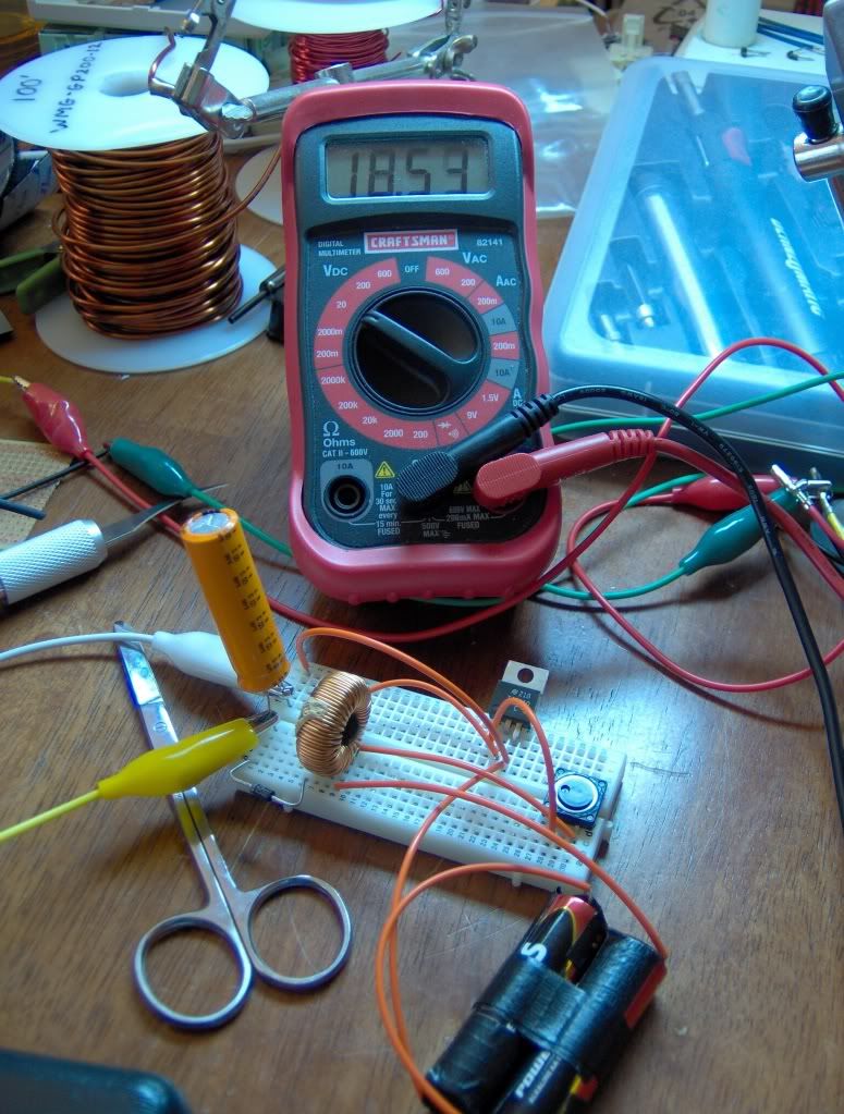
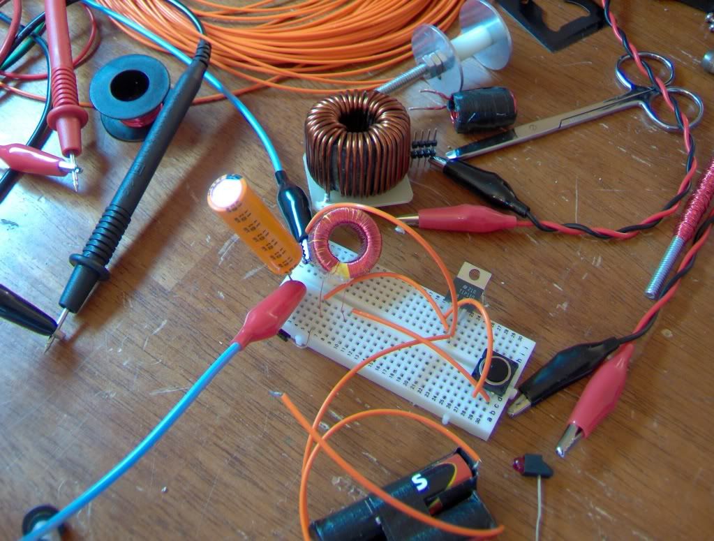
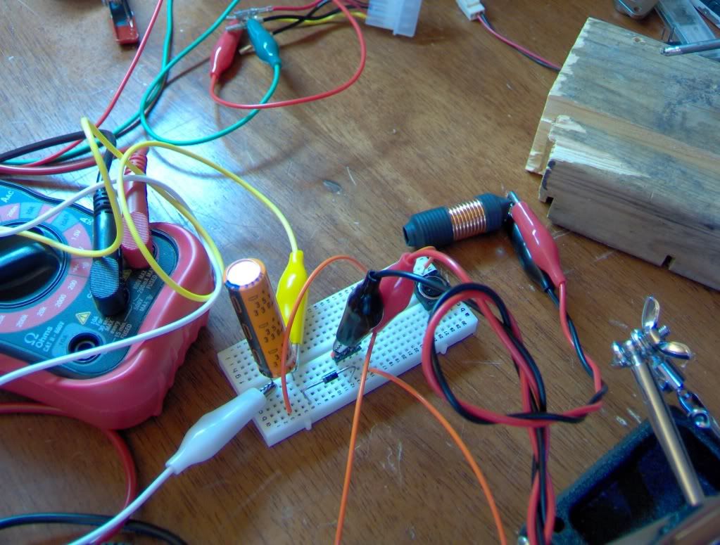
    So, knowing all this, I threw together a quick circuit to test the design, substituting a manual button for the 555 timer and transistor just because I wanted to see what exactly is going on. Also, I was too lazy to bother with the uC.. It works quite well, though slowly since I'm manually initiating each stage...but it works, and that's what's important.


    I'm gonna try this circuit with a few different inductors I have lying around, see what the difference is, but I'm not really hugely concerned about the charging speed right now.


    Hopefully I'll be working on this more regularly now, but no promises...my summer is turning out to be a lot busier than it was supposed to be.

    On a side note, does anyone know where I can find mechanical meter gauges inexpensively? I want to have a mechanical gauge for each capacitor bank, but everywhere I look they're really expensive. I want each to have a range of from 0V to 1kV, which doesn't help...
    That we enjoy great advantages from the inventions of others, we should be glad of an opportunity to serve others by any invention of ours, and this we should do freely and generously.
    --Benjamin Franklin
    TBCS 5TB Club :: coilgun :: bench PSU :: mightyMite :: Zeus :: E15 Magna EV

  2. #2
    If you can't hack it, you don't own it! Oneslowz28's Avatar
    Join Date
    Mar 2007
    Location
    Aiken, Sc
    Posts
    5,084

    Default Re: Coilgun

    Subscribed!

    There is a pretty good video that describes inductors on youtube. It's titled "Make Presents The Inductor"

  3. #3
    Will YOU be ready when the zombies rise? x88x's Avatar
    Join Date
    Oct 2008
    Location
    MD, USA
    Posts
    6,334

    Default Re: Coilgun

    Thanks. Here it is for anyone interested. It's a good explanation of the theory behind inductors, and the affect they have on electrical signals.
    That we enjoy great advantages from the inventions of others, we should be glad of an opportunity to serve others by any invention of ours, and this we should do freely and generously.
    --Benjamin Franklin
    TBCS 5TB Club :: coilgun :: bench PSU :: mightyMite :: Zeus :: E15 Magna EV

  4. #4
    Will YOU be ready when the zombies rise? x88x's Avatar
    Join Date
    Oct 2008
    Location
    MD, USA
    Posts
    6,334

    Default Re: Coilgun

    Well, I spent about a bit tonight relearning how transistors work. ...yeah, I kinda slept through most of my circuits course. <_< >_> Somehow I managed to ace all the labs though. *shrugs*

    Anyways, once I figured out what I was doing, I threw this circuit together to get the manual switch removed another level from it. ..still too lazy to mess with the uC...yeah...I'll get on that tomorrow. Right..tomorrow..

    Right, so, here's the charging circuit now, with my multimeter showing the voltage across the capacitor to show you it is actually working. It drops off pretty fast when I stop charging it, but I'd say charging to 18V off a 3V source in about 5 seconds of my manual switching is pretty good. It takes probably about 10 seconds at a switching rate of ~3-4Hz to get up to 20V, but then takes probably at least another 10 seconds to get up to 30V. I hooked up two caps in series to see how high I could get it before I got sick of pressing the button.. I got up to about 36V after maybe 30-35 seconds, but by that point it had almost slowed down to ~0.05V/s, so I decided to stop. I'll get the uC hooked up tomorrow and see what I can do about getting some real timings.


    Some of you may notice that the inductor changed. I mentioned that I was gonna try throwing some of my other inductors at it? Yeah...this one works almost twice as fast as the other one. O_O I did not expect that. Especially since according to my calculations the first one should have a higher inductance value. Though, come to think of it, the equation I was using didn't factor in multiple layers, which the first one had, so my value for that one is probably wrong.. If my math is right, and it always is ( eh? eh? anyone?), this inductor should have a value of 148.7mH. I'll probably end up digging up or finding a nice ferrite core and winding my own, especially once I'm charging a 700V capacitor bank.. Ah well, this one works for now.
    That we enjoy great advantages from the inventions of others, we should be glad of an opportunity to serve others by any invention of ours, and this we should do freely and generously.
    --Benjamin Franklin
    TBCS 5TB Club :: coilgun :: bench PSU :: mightyMite :: Zeus :: E15 Magna EV

  5. #5
    If you can't hack it, you don't own it! Oneslowz28's Avatar
    Join Date
    Mar 2007
    Location
    Aiken, Sc
    Posts
    5,084

    Default Re: Coilgun

    I have a crapload of small inductors. If you nail down the h you need I might have one.

  6. #6
    Will YOU be ready when the zombies rise? x88x's Avatar
    Join Date
    Oct 2008
    Location
    MD, USA
    Posts
    6,334

    Default Re: Coilgun

    Well, I realized I was using the wrong formula for finding the inductance of the second inductor as well, what with it being a toroid and all... So, using proper equations for both, it turns out the first was a 124mH inductor, and the second is a 234mH. I also checked on the manufacturer stats on the inductor that the guy who did the ible I linked used, and his is a 390mH.

    I have some PCBs that I've been meaning to tear apart, and a few of them have nice big toroidal inductors on them...we'll see how they work.
    That we enjoy great advantages from the inventions of others, we should be glad of an opportunity to serve others by any invention of ours, and this we should do freely and generously.
    --Benjamin Franklin
    TBCS 5TB Club :: coilgun :: bench PSU :: mightyMite :: Zeus :: E15 Magna EV

  7. #7
    Will YOU be ready when the zombies rise? x88x's Avatar
    Join Date
    Oct 2008
    Location
    MD, USA
    Posts
    6,334

    Default Re: Coilgun

    So, no work on this directly tonight, but after burning out one of my alligator-clip jumpers a while back, I decided I needed some a little more...robust.

    So, today I stopped at Harbor Freight and picked up a set of clips of various sizes, and I found this on sale. At $50, I wouldn't have gotten it, but for $30? Yeah, I think that's worth it.
    17' 10AWG
    20' 12AWG
    22' 14AWG
    39' 16AWG
    86' 18AWG
    124' 20AWG
    64' 22AWG
    All twisted copper single-conductor.
    Plus:
    30' copper/alu 2-conductor speaker cable
    20' of something they call 'zip cord', which appears to be two 18AWG twisted copper conductors running parellel
    20' of something they call 'bell wire', which appears to be two 22AWG solid copper conductors both individually insulated and inside an insulating sheath
    Plus, it came with the nice rack.


    So, putting those together I made myself some better jumpers.
    On the outside we have two lines (red) with pretty big clips joined by 10AWG wire (no stamped current rating, but I'm guessing it's pretty high). Going in, we have a single line (brown) joining two 5A rated clips with 14AWG wire. Unfortunately, the set only came with the two clips, not 4, so I only have one line that size. Also, I didn't actually notice the 12AWG spool until I was typing it out above, which is why that line is 14 instead of 12. Then, on the inside we have four lines (blue) with two different size standard alligator clips (two lines with each size) joined by 18AWG wire.


    There was another type of clip in the set that I can't for the life of me figure out how to connect. Any ideas?
    That we enjoy great advantages from the inventions of others, we should be glad of an opportunity to serve others by any invention of ours, and this we should do freely and generously.
    --Benjamin Franklin
    TBCS 5TB Club :: coilgun :: bench PSU :: mightyMite :: Zeus :: E15 Magna EV

  8. #8
    Will YOU be ready when the zombies rise? x88x's Avatar
    Join Date
    Oct 2008
    Location
    MD, USA
    Posts
    6,334

    Default Re: Coilgun

    Well, I figured out the attachment style for those clips, so now I have two more ~2.5' 14AWG jumpers (12AWG wouldn't quite fit around the screws correctly ).

    I also ran across two websites that some might find interesting.

    A listing of a bunch of different coilgun projects.
    http://www.coilgun.ru/

    A site that has a lot of information about coilgun design, getting into much more detail than any other source I've found.
    http://www.coilgun.info/about/home.htm
    That we enjoy great advantages from the inventions of others, we should be glad of an opportunity to serve others by any invention of ours, and this we should do freely and generously.
    --Benjamin Franklin
    TBCS 5TB Club :: coilgun :: bench PSU :: mightyMite :: Zeus :: E15 Magna EV

  9. #9
    Will YOU be ready when the zombies rise? x88x's Avatar
    Join Date
    Oct 2008
    Location
    MD, USA
    Posts
    6,334

    Default Re: Coilgun

    Not much today, but I did get some done. I decided to attack the inductor problem first. Unfortunately, even they're big and intimidating, the inductors I pulled off the Plasma PCB, they weren't actually very...inductive... Even the big one next to the board in the picture is only a 134mH inductor. So instead I took apart one of the smaller toroid inductors from the board and re-wound it with a single layer of 30AWG magnet wire. And no, I'm not gonna count those windings to figure out the inductance.. -_^


    After making it, I didn't really expect it to work that well, tbh, but once I hooked it up, the change was pretty impressive. With the 234mH coil I had been using before, it took 9.3s to go from 2.5V (base voltage). With this one, it only takes 6.4s. I'm considering breaking this one down too and rewinding it with several more layers, just for the hell of it. ...the only problem is that it took about an hour to wind the first layer... -_^ Hmmm, or maybe I could just wind more layers on top of the first...I'm sure I could find a use for a smaller, secondary inductor.
    That we enjoy great advantages from the inventions of others, we should be glad of an opportunity to serve others by any invention of ours, and this we should do freely and generously.
    --Benjamin Franklin
    TBCS 5TB Club :: coilgun :: bench PSU :: mightyMite :: Zeus :: E15 Magna EV

  10. #10
    I've got the madcow, what's your excuse? Bopher's Avatar
    Join Date
    May 2007
    Location
    Carlisle, PA
    Posts
    980

    Default Re: Coilgun

    Quote Originally Posted by x88x View Post
    If my math is right, and it always is ( eh? eh? anyone?)
    Tony Stark
    Now get to work on the ARC reactor that will power this thing

    "Technical neglect is one of the worst kinds of neglect, won't you sponsor an octal or adsl2 card so they can someday grow up into big capable adsl2+ cards? random celebrity does."

Posting Permissions

  • You may not post new threads
  • You may not post replies
  • You may not post attachments
  • You may not edit your posts
  •