Found it, thanks! AND they've got a request samples button...I'm going to get one or two. HUGE thanks!!
http://www.linear.com/product/LTC3862


Found it, thanks! AND they've got a request samples button...I'm going to get one or two. HUGE thanks!!
http://www.linear.com/product/LTC3862
Arctic Cat * Maximum Security * Cribbage Board * Rockin Case * Armor Redux
Tempest SXR * Power House * Red Comet * ICHIWZ * Acrylic Headphone Hook
Continuing sponsorship support from PCBoard.ca
actually...one little problem...of course...their chips are all 0.15" SMD's!!!that's useless for me lol
Arctic Cat * Maximum Security * Cribbage Board * Rockin Case * Armor Redux
Tempest SXR * Power House * Red Comet * ICHIWZ * Acrylic Headphone Hook
Continuing sponsorship support from PCBoard.ca
hell I should just get this! up to 55V/3A output!
http://cgi.ebay.com/12V-24V-Step-up-...item2a0dcb7b16
Arctic Cat * Maximum Security * Cribbage Board * Rockin Case * Armor Redux
Tempest SXR * Power House * Red Comet * ICHIWZ * Acrylic Headphone Hook
Continuing sponsorship support from PCBoard.ca
there you go. all done and ready for you. for ten bones i'd forget about all teh research and fabing you'd have to do and just buy that.
yea I'm going to scoop up one of those, that makes things VERY simple
Thanks again for that info though, it was much appreciated
Arctic Cat * Maximum Security * Cribbage Board * Rockin Case * Armor Redux
Tempest SXR * Power House * Red Comet * ICHIWZ * Acrylic Headphone Hook
Continuing sponsorship support from PCBoard.ca
Update time!
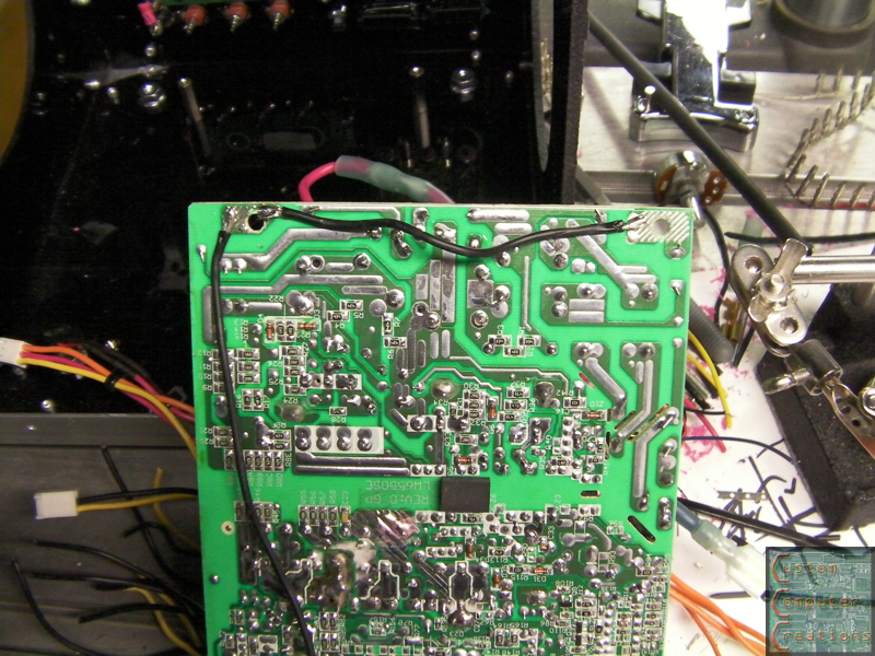
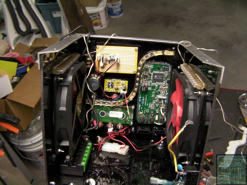
I started off the night by soldering wire to the PCB of the PSU to connect the corner grounds. These would normally be connected by the steel case that it's mounted to, but in this case it's mounted to plastic, so this had to be done.
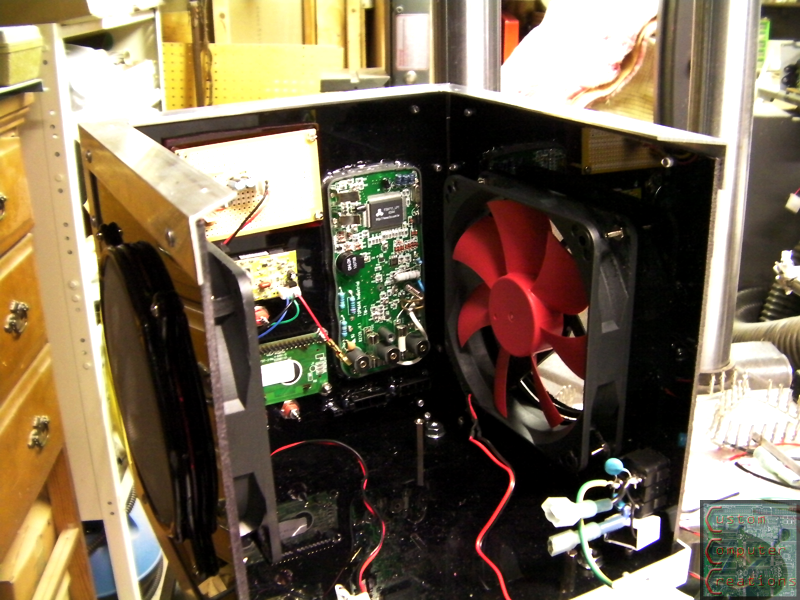
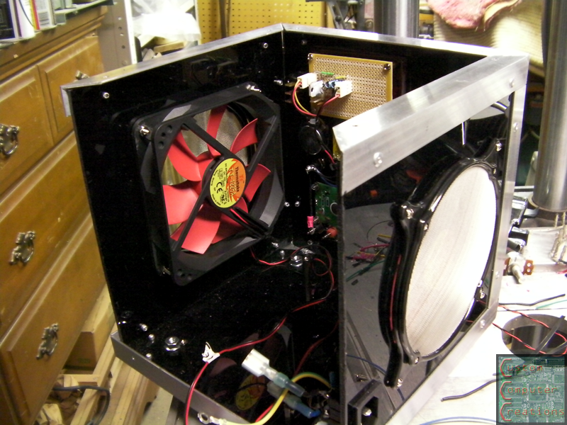
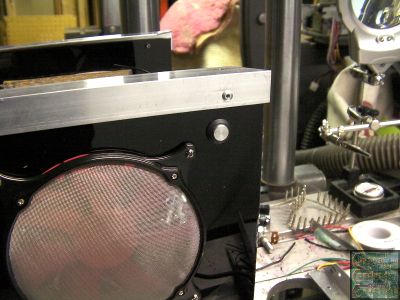
Next up I installed the fans, one intake and one exhaust, and the mesh covers over the outside.
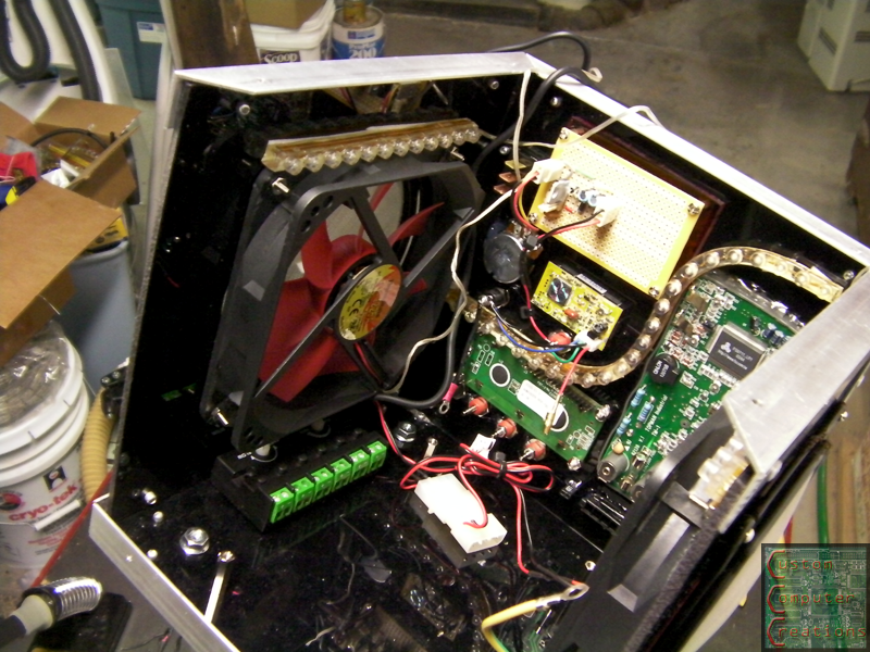
Next up I worked on the interior lighting. I had to do something to snazz it up a bitI used one long white LED strip and 2 shorter amber ones. I stuck these inside with double-sided tape. The control box is under the LH fan, with the green terminal blocks.
I then drilled a hole and installed the power button for the lights (in case they get annoying for whatever reason)
And a short vid of the lighting. The amber LEDs stay on while the white ones blink slowly.
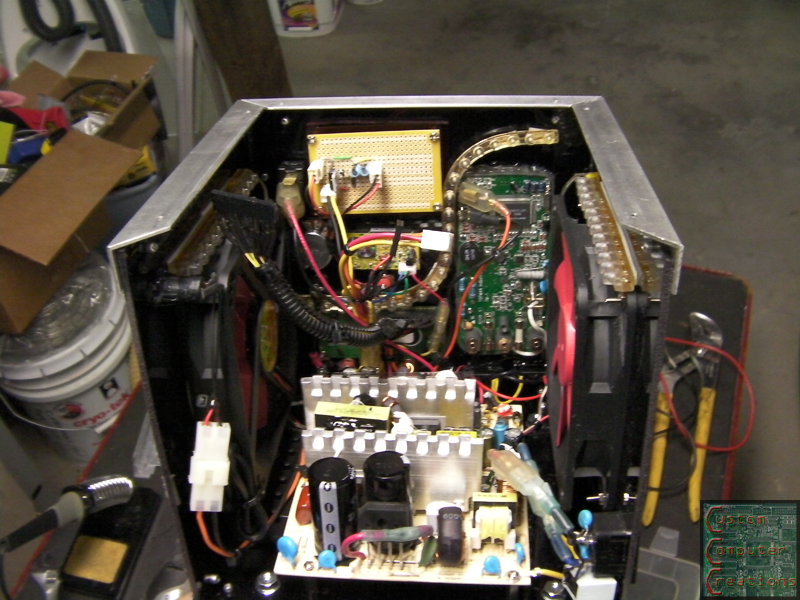
And then I installed the PSU and hooked up all the wiring.
And it works!
And a (crappy - need to redo it with better lighting) vid!
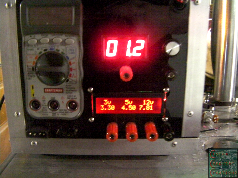
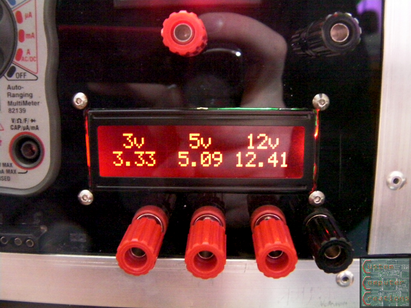
As you can see I need to tweak the coding, as the 5v and 12v reading are a tad off. I checked them with the meter to be sure, and the output is correct, but the LCD reading is incorrect.
I'm also having a few issues with the multimeter, as it's being powered by 3v from the PSU, and grounded to the PSU. First off, because it's grounded through the PSU, it shares internal grounds with all the ground binding posts, so only the positive test lead is needed. Second, this meter's readings are low for some reason, by about 1.5v or so. I wonder if it's backfeeding through the PCBMaybe I need to put diodes in the supply line to the meter?
I tested it with a separate meter, and all the readings are correct. I may just take the 3v and gnd off the meter and use batteries with it again to keep it isolated. I'll try it and see how it works out.
That's it for now!
Arctic Cat * Maximum Security * Cribbage Board * Rockin Case * Armor Redux
Tempest SXR * Power House * Red Comet * ICHIWZ * Acrylic Headphone Hook
Continuing sponsorship support from PCBoard.ca
ok so I just ordered this 12v to 24v booster, so in 3-4 weeks it'll be here, which means I've got plenty of time to sort out the coding for the LCD
Arctic Cat * Maximum Security * Cribbage Board * Rockin Case * Armor Redux
Tempest SXR * Power House * Red Comet * ICHIWZ * Acrylic Headphone Hook
Continuing sponsorship support from PCBoard.ca
Well I got the code sorted, just needed to make some final adjustments.
the code:
And the final result. It is accurate to within 0.05v, which for what I'm going to use this for is more than accurate enoughCode:/*Arduino Controlled Voltage Monitor Code by Will Lyon 2/28/2011 Code for project Power House on TBCS http://www.thebestcasescenario.com*/ #include <LiquidCrystal.h> //Initialize the library with the numbers of the interface pins LiquidCrystal lcd(7, 8, 9, 10, 11, 12); void setup() { lcd.begin(16, 2); //Set up the LCD's number of columns and rows lcd.print(" POWER HOUSE"); //First line opening message lcd.setCursor(0, 1); lcd.print("Desktop Pwr Unit"); //Second line opening message delay(5000); lcd.setCursor(0, 1); //Clear bottom line lcd.print(" "); lcd.setCursor(0,0); lcd.print(" 3v 5v 12v"); //Update top line readout } void loop() { lcd.setCursor(0, 1); float f = analogRead(0) * 4.92 / 1023; // 3.3 => 9.9 lcd.print(f, 2); // print float with two decimals lcd.setCursor(6, 1); float g = analogRead(5) * 8.05 / 1023; // 5.0 => 9.9 lcd.print(g, 2); lcd.setCursor(11, 1); float h = analogRead(4) * 20.88 / 1023; // 12.0 => 25.0 lcd.print(h, 2); delay(1000); }
Now all that's left to do is make the back door, and wait for my 12v to 24v converter to show up!
Arctic Cat * Maximum Security * Cribbage Board * Rockin Case * Armor Redux
Tempest SXR * Power House * Red Comet * ICHIWZ * Acrylic Headphone Hook
Continuing sponsorship support from PCBoard.ca

So, are you going to leave thr voltage connectors the way they are, or dye them?


Looking at the perspex hole for the LED you can see excess glow around the edges of the module - A few pieces of basic black electrical tape would quickly take care of that without causing any hassle if it needed to be taken apart again....
Current Projects: Lobo | Unimatrix | High Voltage | Antec 900 Revamp (Phase 2)
Completed Projects: General Lee | Synergy Green | Liquid Yellow
Planned Projects: K-9-PC | Limey
 Posting Permissions

 Reply With Quote